Table of Contents
Advertisement
Quick Links
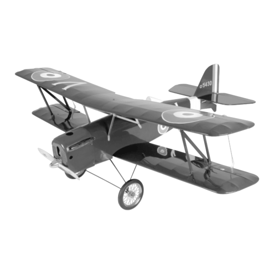
INSTRUCTIONS FOR FINAL ASSEMBLY
Specifications:
The Modeltech SE5a Scout ARF is distributed
Wing Span: 49.5 Inches (Top and Bottom)
exclusively by Global Hobby Distributors
Wing Area: 792 Square Inches
18480 Bandilier Circle, Fountain Valley, CA 92708
Length: 41 Inches
Weight RTF: 5.5 - 6.5 Pounds
Wing Loading: 16 - 19 Ounces Per Square Foot
Functions: Ailerons, Elevator, Rudder & Throttle
All contents copyright © 2004, Global Hobby
Engine Required: .40 - .52 Two-Stroke
Distributors Version V1.0 February 2004
.52 - .61 Four-Stroke
Kit Product Number 123680
Radio Required: 4Ch or More w/3 Standard Servos
and 2 Mini Servos
1
Advertisement
Table of Contents

Related Manuals for Model Tech SE5a SCOUT


Summary of Contents for Model Tech SE5a SCOUT
- Page 1 INSTRUCTIONS FOR FINAL ASSEMBLY Specifications: The Modeltech SE5a Scout ARF is distributed Wing Span: 49.5 Inches (Top and Bottom) exclusively by Global Hobby Distributors Wing Area: 792 Square Inches 18480 Bandilier Circle, Fountain Valley, CA 92708 Length: 41 Inches Weight RTF: 5.5 - 6.5 Pounds Wing Loading: 16 - 19 Ounces Per Square Foot Functions: Ailerons, Elevator, Rudder &...
-
Page 2: Table Of Contents
Section 1: Our Recommendations ..........4 Section 16: Final Assembly ............. 34 Section 2: Tools and Supplies Required ........5 Section 17: Balancing the SE5a Scout ARF ......37 Section 3: Kit Contents ............. 5 Section 18: Control Throws ............. 37 Section 4: Replacement Parts .......... -
Page 3: Introduction
INTRODUCTION Thank you for purchasing the Modeltech SE5a Scout ARF. Before completing the final assembly of your new airplane, please carefully read through this instruction manual in its entirety. Doing so will ensure your success the first time around! MODELTECH SE5a SCOUT ARF FEATURES... -
Page 4: Section 1: Our Recommendations
What Engine Should I Use? The SE5a Scout ARF will fly well with a variety of different engines. The airplane is designed to be flown with .40 - .52 size two-stroke engines or .52 - .61 size four-stroke engines. Whether you plan on using a two-stroke or a four-stroke engine, the firewall has been set up for the engine to be mounted upright. -
Page 5: Section 2: Tools And Supplies Required
SECTION 2: TOOLS AND SUPPLIES REQUIRED The tools and supplies listed below will be necessary to finish the assembly of your Modeltech SE5a Scout ARF. We suggest having these items on hand before beginning assembly. Kwik Bond Thin C/A # 887500... - Page 6 KIT CONTENTS, CONTINUED..LANDING GEAR ASSEMBLY ENGINE MOUNT ASSEMBLY (2) Wire-Spoke Wheels (2) Engine Mounting Beams (2) Prebent Steel Struts w/7mm I.D. Steel Collars (4) M3 x 18mm Socket-Cap Screws (1) Prebent Steel Support Strut (4) M3 x 25mm Socket-Cap Screws (1) 16"...
-
Page 7: Section 4: Replacement Parts
SECTION 4: REPLACEMENT PARTS Global stocks a complete line of replacement parts for your Modeltech SE5a Scout ARF. Listed below are the replacement parts that are available along with their respective part numbers for easy ordering convenience. We suggest ordering directly from your local dealer. -
Page 8: Section 6: Stabilizer Installation
SECTION 6: STABILIZER INSTALLATION YOU'LL NEED THE FOLLOWING PARTS FROM THE KIT: (1) Plywood Wing-Screw Doubler (W41) (1) Fuselage (1) Bottom Wing w/Ailerons (2) M4 x 30mm Machine Screws (2) M4 Flat Washers (1) Horizontal Stabilizer w/Elevator (1) Vertical Stabilizer w/Rudder YOU'LL NEED THE FOLLOWING TOOLS AND SUPPLIES: Kwik Bond 30 Minute Epoxy Builder's Triangle... - Page 9 STEP 2: ALIGNING THE VERTICAL STABILIZER Remove the rudder and three hinges from the vertical stabilizer and set them aside for now, then remove the elevator and four hinges from the horizontal stabilizer and set them aside for now, too. Using a modeling knife, cut away and remove the covering material from over the bottom of the precut slot in the middle of the horizontal stabilizer.
- Page 10 Mix and apply a generous amount of 30 minute epoxy to the gluing surfaces of the vertical stabilizer and to the vertical stabilizer mounting slot in the top of the horizontal stabilizer. Push the vertical stabilizer down into place and realign it, double-checking the alignment once more before the epoxy sets up.
- Page 11 With the stabilizer assembly held firmly in place, look from the front of the airplane at both the wing and the horizontal stabilizer. When aligned properly, the horizontal stabilizer should be parallel to the wing. IMPORTANT If the stabilizer assembly is out of alignment, remove it and use 220 grit sandpaper with a sanding block to sand down the higher side of the stabilizer mounting platform, then reinstall the stabilizer assembly and check the alignment once more.
-
Page 12: Section 7: Top Wing Installation
SECTION 7: TOP WING INSTALLATION YOU'LL NEED THE FOLLOWING PARTS FROM THE KIT: (4) M3 Lock Nuts (1) Top Wing w/Ailerons (2) Prebent Aluminum Cabane Struts (6-3/4" Long) (4) Precovered Outer Struts (W43) (2) Prebent Aluminum Cabane Struts (5-5/8" Long) (2) Precovered Outer Strut Supports (W42) (2) Prebent Aluminum Cabane Struts (7-5/8"... - Page 13 Repeat the previous procedures to mount the remaining two 5-5/8" long and 6-3/4" long cabane struts to the other side of the fuselage, using two M3 x 10mm machine screws and two M3 flat washers. Carefully test-fit and install one 7-5/8" long cabane strut to the forward and rear cabane struts on one side of the fuselage, using two M3 x 10mm machine screws, four M3 flat washers and two M3 hex nuts.
- Page 14 STEP 4: ALIGNING AND MOUNTING THE TOP WING With the bottom wing installed onto the fuselage, set the fuselage in your airplane stand and secure it firmly to the stand, using a couple of large rubber bands or several small weights. IMPORTANT It's important that the fuselage be secured firmly and cannot move during the next few procedures.
-
Page 15: Section 8: Control Surface Hinging
INFORMATION ABOUT WING ASSEMBLY BEFORE FLIGHT After you're done with the complete assembly of the airplane, but before you fly the airplane for the first time, we strongly suggest that you apply Blue Threadlocker to the machine screws and nuts that secure the cabane strut assembly together. -
Page 16: Section 9: Engine Installation
Remove the T-pins from the hinges, and while holding the aileron tight against the wing, pivot the aileron down about 45º and apply 5-6 drops of thin C/A to the exposed area of each hinge. Turn the wing over and repeat for the other side of the hinges. - Page 17 STEP 1: INSTALLING THE ENGINE MOUNTING BEAMS IMPORTANT When installed, the engine mounting beams are spaced to fit the Magnum XLS .40 - .52 size two- stroke engines and the Magnum XL .52 - .61 size four-stroke engines. If the width of the engine you choose is not the same, you will need to modify the spacing of the beams.
-
Page 18: Section 10: Fuel Tank Assembly & Installation
SECTION 10: FUEL TANK ASSEMBLY & INSTALLATION YOU'LL NEED THE FOLLOWING PARTS FROM THE KIT: (1) Fuel Pick-Up "Clunk" (1) 240cc Fuel Tank (1) Large Diameter Metal Plate (1) M3 x 20mm Machine Screw (1) Small Diameter Metal Plate (1) Silicon Fuel Tubing (2) Aluminum Tubing (1) Metal Neck-Reinforcement Ring (1) Rubber Stopper... - Page 19 STEP 2: INSTALLING THE RUBBER STOPPER ASSEMBLY Carefully push the metal neck-reinforcement ring over the neck of the molded fuel tank opening. Carefully push the rubber stopper assembly into the fuel tank opening and rotate the stopper assembly until the aluminum vent tube rests just below the top of the tank.
-
Page 20: Section 11: Throttle Control System Installation
SECTION 11: THROTTLE CONTROL SYSTEM INSTALLATION YOU'LL NEED THE FOLLOWING PARTS FROM THE KIT: (1) 16" Pushrod Wire w/Z-Bend (1) Plywood Servo Tray (D36) (1) Adjustable Servo Connector Assembly YOU'LL NEED THE FOLLOWING TOOLS AND SUPPLIES: 1/16" & 5/64" Drill Bits Kwik Bond Thin C/A Kwik Bond 5 Minute Epoxy Ernst Airplane Stand... - Page 21 STEP 3: INSTALLING THE THROTTLE PUSHROD & ADJUSTABLE CONNECTOR IMPORTANT INFORMATION ABOUT THROTTLE PUSHROD SETUP FOR FOUR-STROKE ENGINES The hole in the firewall for the throttle pushrod wire has been predrilled from the factory. This hole is positioned to line up with the throttle arm on most .40 - .52 size two-stroke engines.
-
Page 22: Section 12: Elevator & Rudder Control Systems Installation
Connect your radio system and plug the throttle servo into the receiver. Check to ensure that the throttle servo output shaft is rotating in the correct direction. When the throttle control stick is moved forward, from the idle to the full throttle position, the servo output shaft should rotate in the correct direction to open your engine's throttle barrel. - Page 23 Install the elevator and rudder servos into the cutouts in the plywood servo tray, making sure to first drill 1/16" diameter pilot holes for the mounting screws. IMPORTANT The servo output shafts should be toward the back of the fuselage, as shown. STEP 2: ASSEMBLING THE ELEVATOR AND RUDDER PUSHRODS Using a modeling knife, cut both of the 26"...
- Page 24 Using a modeling knife, cut away and remove the covering material from over the elevator pushrod exit hole in the left side of the fuselage. The hole is located 3-3/4" in front of the rudder hinge line and 7/8" below the bottom of the horizontal stabilizer.
- Page 25 STEP 4: INSTALLING THE RUDDER PUSHROD ASSEMBLY The rudder pushrod assembly is installed in the same manner as the elevator pushrod assembly was installed. Begin by using a modeling knife to cut away and remove the covering material from over the rudder pushrod exit hole in the right side of the fuselage.
-
Page 26: Section 13: Aileron Control System Installation
SECTION 13: AILERON CONTROL SYSTEM INSTALLATION YOU'LL NEED THE FOLLOWING PARTS FROM THE KIT: (2) Nylon 90º Snap Keepers (2) Aileron Servo Hatch Covers (W34) (4) Aileron Servo Mounting Blocks (W35) (2) M2 x 20mm Machine Screws (2) 1-1/4" Threaded Wires w/Z-Bend (2) M2 x 25mm Machine Screws (8) M2 x 10mm Flange-Head Wood Screws (2) 7-1/8"... - Page 27 Using modeling knife, cut away and remove the covering material from over the precut slot in one servo hatch cover. Temporarily place the aileron servo, along with two servo mounting blocks, onto the bottom of the servo hatch cover. The servo arm should be inserted through, and centered within, the precut slot, as shown.
- Page 28 While holding the servo hatch cover assembly firmly in place, carefully drill four 1/16" diameter pilot holes into the servo hatch cover and through the mounting blocks in the wing. Locate each of the four holes 1/8" in from each corner of the servo hatch cover.
- Page 29 Use a couple of pieces of masking tape, taped between the aileron and the wing, to hold the aileron centered. Thread one nylon clevis onto the pushrod wire and snap it into the outermost hole in the control horn. Hold the pushrod wire with a pair of pliers to prevent it from turning while installing the clevis.
-
Page 30: Section 14: Landing Gear Installation
Thread one nylon clevis onto one of the 7-1/8" long aileron interlink pushrod wires. When the clevis is in the correct position, the distance between the 90º bend in the pushrod wire and the nylon clevis pin should be 7-5/8". Hold the pushrod wire with a pair of pliers to prevent it from turning while installing the clevis. - Page 31 STEP 1: INSTALLING THE LANDING GEAR WIRES Using a modeling knife, cut away and remove the covering material from over the precut landing gear mounting slot in the bottom of the fuselage. The slot is 4-1/4" long and 5/16" wide, and is located 5/8"...
- Page 32 With the bottom wing installed, line up the back of the steel support strut with the wing-screw doubler. When positioned properly, the support strut should be centered from side to side over the wing-screw doubler and the support strut should be just in front of the two wing hold-down screws.
-
Page 33: Section 15: Cowling Installation
SECTION 15: COWLING INSTALLATION YOU'LL NEED THE FOLLOWING PARTS FROM THE KIT: (1) Fiberglass Cowling (4) M3 Flat Washers (4) M3 x 6mm Wood Screws YOU'LL NEED THE FOLLOWING TOOLS AND SUPPLIES: Kwik Bond Thin C/A Ruler # 1 Phillips Head Screwdriver Pencil Electric Drill 220 Grit Sandpaper w/Sanding Block... -
Page 34: Section 16: Final Assembly
STEP 2: MOUNTING THE COWLING With the cowling held firmly in alignment, drill 1/16" diameter pilot holes into the cowling and through the sides of the fuselage for the four wood screws. Locate two holes on each side of the cowling, 3/16" in front of the back edge of the cowling. - Page 35 STEP 1: INSTALLING THE WINDSCREEN & HEADREST FAIRING Using a pair of scissors, carefully cut out the windscreen along the molded scribe lines. Using 220 grit sandpaper with a sanding block, carefully sand the edges of the windscreen smooth and straight. Using a pair of scissors, carefully cut out the headrest along its molded base, leaving about 1/8"...
- Page 36 If any air bubbles form under the decals you can "prick" the bubbles with a pin to release the air. At this time, assembly of your new SE5a Scout ARF is completed. You might want to take the time now to add those small personal scale details to your new airplane.
-
Page 37: Section 17: Balancing The Se5A Scout Arf
SECTION 18: CONTROL THROWS We recommend setting up the SE5a Scout ARF using the control throws listed below. These control throws are suggested for initial test-flying because they will allow the airplane to fly smoother and make it easier to control. -
Page 38: Section 19: Preflight Check & Safety
CONTROL THROWS, CONTINUED..Once you're familiar with the flight characteristics of the airplane, you might want to increase the control throws to the sport-flying settings listed below. These control throws will make the airplane more responsive and allow you to do basic barnstorming aerobatics with ease. -
Page 39: Product Evaluation Sheet
Global Hobby Distributors will not disclose the information it collects to outside parties. Global Hobby Distributors does not sell, trade, or rent your personal information to others. Your privacy is important to us. Kit: Modeltech SE5a Scout ARF # 123680 Was any of the assembly difficult for you? If yes, please explain. - Page 40 _____________________________ _____________________________ Post Office will not deliver _____________________________ without proper postage (Return Address Here) Global Hobby Distributors Attn: Global Services 18480 Bandilier Circle Fountain Valley CA 92728-8610 Fold along dotted line...