Table of Contents
Advertisement
INSTRUCTIONS FOR FINAL ASSEMBLY
The Modeltech Dragon Lady 60 ARF is distributed
exclusively by Global Hobby Distributors 18480
Bandilier Circle, Fountain Valley, CA 92708
All contents copyright © 2003, Global Hobby
Distributors Version V2.0 April 2003
Kit Product Number 123761
Need help or have any questions? Call us at 1-714-963-0329 or send us an Email at service@globalhobby.net
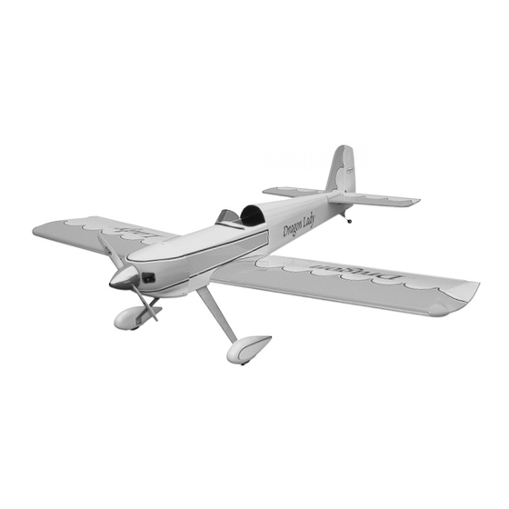
.60 - 1.20 Size
Sport-Aerobatic A.R.F.
Specifications:
Wing Span: 66 Inches
Wing Area: 872 Square Inches
Length: 55 Inches
Weight RTF: 6 - 6.75 Pounds
Functions: Ailerons, Elevator, Rudder and Throttle
Power: .61 - 1.08 2-Stroke or .91 - 1.20 4-stroke
Radio: 4 Channel w/4 Standard Servos
1
Advertisement
Table of Contents

Related Manuals for Model Tech Dragon Lady


Summary of Contents for Model Tech Dragon Lady
-
Page 1: Specifications
.60 - 1.20 Size Sport-Aerobatic A.R.F. INSTRUCTIONS FOR FINAL ASSEMBLY Specifications: The Modeltech Dragon Lady 60 ARF is distributed Wing Span: 66 Inches exclusively by Global Hobby Distributors 18480 Wing Area: 872 Square Inches Bandilier Circle, Fountain Valley, CA 92708 Length: 55 Inches Weight RTF: 6 - 6.75 Pounds... -
Page 2: Table Of Contents
Section 20: Final Assembly ..............34 Section 21: Balancing the Dragon Lady 60 ARF ........35 Section 22: Lateral Balancing the Dragon Lady 60 ARF ......36 Section 23: Control Throws ..............36 Section 24: Preflight Check & Safety ............37 Section 25: Flying the Dragon Lady 60 ARF ........... -
Page 3: Introduction
INTRODUCTION Thank you for purchasing the Modeltech Dragon Lady 60 ARF. Before completing the final assembly of your new airplane, please carefully read through this instruction manual in its entirety. Doing so will ensure your success the first time around! -
Page 4: Section 1: Our Recommendations
What Engine Should I Use? The Dragon Lady 60 will accept a wide variety of engines, so which engine you choose really depends on how you want to fly the airplane. For general sport flying, a .61 two stroke or .91 four stroke would be an ideal choice. Either of these engines will provide good overall performance and will pull the airplane through most aerobatic maneuvers with ease. -
Page 5: Section 2: Tools And Supplies Required
SECTION 2: TOOLS AND SUPPLIES REQUIRED The tools and supplies listed below will be necessary to finish the final assembly of your Dragon Lady 60 ARF. We suggest having these items on-hand before beginning assembly. Kwik Bond Thin C/A # 887500... -
Page 6: Section 4: Metric Conversion Chart
RUDDER CONTROL SYSTEM TAIL WHEEL ASSEMBLY 31" Threaded Wire Nylon Tail Wheel Bracket Nylon Control Horn w/Backplate Nylon Tail Wheel Tiller Arm 2mm x 20mm Machine Screws Prebent Tail Wheel Wire Nylon Clevis Tail Wheel Nylon 90º Snap Keeper Wheel Collars w/Set Screws C/A Style Hinges Nylon Spacer 2.5mm x 12mm Wood Screw... -
Page 7: Section 5: Replacement Parts
SECTION 5: REPLACEMENT PARTS Global stocks a complete line of replacement parts for your Modeltech Dragon Lady 60 ARF. Listed below are the replacement parts that are available along with their respective part numbers for easy ordering convenience. We suggest ordering directly from your local dealer. -
Page 8: Section 7: Wing Assembly
SECTION 7: WING ASSEMBLY YOU'LL NEED THE FOLLOWING PARTS FROM THE KIT: (1) Hardwood Wing Joiner (W3) (1) Right Wing Panel w/Aileron (1) Left Wing Panel w/Aileron YOU'LL NEED THE FOLLOWING TOOLS AND SUPPLIES: Kwik Bond 30 Minute Epoxy Masking Tape Excel Modeling Knife Paper Towels Ruler... - Page 9 Slide both wing panels together with the wing joiner temporarily installed (without using glue). Again, make sure the wing joiner's "V-shape" is toward the top of the wing panels. This will help ensure the proper dihedral angle. Look carefully at the center section joint: the wing panels should fit together tightly with few or no gaps in the joint. If the wing panels do not fit together properly, remove the wing joiner and use 220 grit sandpaper with a sanding block to lightly sand the edges and tips of the joiner, until you are satisfied with the fit.
-
Page 10: Section 8: Wing Mounting
SECTION 8: WING MOUNTING YOU'LL NEED THE FOLLOWING PARTS FROM THE KIT: (2) 5mm Flat Washers (1) Fuselage (2) 5mm x 40mm Machine Screws (2) 5mm Blind Nuts - Optional YOU'LL NEED THE FOLLOWING TOOLS AND SUPPLIES: Kwik Bond Thin C/A Ernst Airplane Stand # 2 Phillips Head Screwdriver Ruler... - Page 11 Using an 5/32" diameter drill bit, drill two holes into the wing and through the plywood wing hold-down block inside the fuselage. Locate one hole in each wing panel, 1-3/4" out from the centerline and 5/8" in front of the trailing edge. IMPORTANT Drill the two holes perpendicular to the bottom surface of the wing.
-
Page 12: Section 9: Stabilizer Installation
SECTION 9: STABILIZER INSTALLATION YOU'LL NEED THE FOLLOWING PARTS FROM THE KIT: (1) Horizontal Stabilizer w/Elevator (1) Vertical Stabilizer w/Rudder YOU'LL NEED THE FOLLOWING TOOLS AND SUPPLIES: Kwik Bond 30 Minute Epoxy 220 Grit Sandpaper w/Sanding Block Excel Modeling Knife Masking Tape Dubro T-Pins Paper Towels... - Page 13 Using a pencil, outline the front of the vertical stabilizer onto the top of the horizontal stabilizer. Remove the vertical stabilizer. Using a modeling knife, carefully cut away and remove the covering material from below the lines you drew. Cut away and remove the covering material from the base of the vertical stabilizer and inside the outline you drew on top of the horizontal stabilizer, too.
- Page 14 With the wing mounted to the fuselage, use a ruler to measure the distance between the tips of the stabilizer and the tips of the wing. Adjust the stabilizer until both of these measurements are equal. If the stabilizer is lined up correctly with the fuselage, the measurements should be very close.
-
Page 15: Section 10: Control Surface Hinging
SECTION 10: CONTROL SURFACE HINGING YOU'LL NEED THE FOLLOWING PARTS FROM THE KIT: (17) C/A Style Hinges YOU'LL NEED THE FOLLOWING TOOLS AND SUPPLIES: Kwik Bond Thin C/A 220 Grit Sandpaper w/Sanding Block Kwik Bond 5 Minute Epoxy Paper Towels Kwik Bond C/A Debonder Rubbing Alcohol Excel Modeling Knife... - Page 16 Slide the aileron and its hinges into the hinge slots in the trailing edge of the wing, making sure that the torque rod is firmly seated in the leading edge of the aileron. Adjust the aileron so that the edges of the aileron don't rub against the edges of the wing.
-
Page 17: Section 11: Tail Wheel Installation
SECTION 11: TAIL WHEEL INSTALLATION YOU'LL NEED THE FOLLOWING PARTS FROM THE KIT: (1) Nylon Tail Wheel Bracket (2) Wheel Collars w/Set Screws (1) Nylon Spacer (1) Nylon Tail Wheel Tiller Arm (1) Prebent Tail Wheel Wire (1) 2.5mm x 12mm Wood Screw (3) 3mm x 12mm Wood Screws (1) Tail Wheel YOU'LL NEED THE FOLLOWING TOOLS AND SUPPLIES:... -
Page 18: Section 12: Main Landing Gear Installation
While holding the tiller arm firmly against the bottom of the rudder, drill a 5/64" diameter pilot hole through both sides of the nylon clasp and through the rudder. Thread the 2.5mm x 12mm wood screw into one side of the clasp, through the rudder and into the other side of the clasp. - Page 19 Step 2: Installing the Wheels & Wheel Pants Using a modeling knife, very carefully cut the wheel opening in each of the two wheel pants, as shown. Use 220 grit sandpaper with a sanding block to carefully sand the edges of the openings smooth. Using a 5/32"...
- Page 20 After the epoxy has fully cured, carefully drill a 3/8" diameter hole through the wheel pant and plywood plate using the 5/32" diameter hole you drilled previously as a guide. The hole will not be centered within (and might even miss part of) the plywood plate.
-
Page 21: Section 13: Engine Installation
Remove the wheel collars, wheel and wheel pant from the threaded axle. Using a 5/32" diameter drill bit, drill a hole into the wheel pant and through the plywood plate, at the mark you drew. Carefully install one 3mm blind nut, from inside the wheel pant, into the hole you just drilled. - Page 22 Step 1: Aligning the Engine Mounting Beams IMPORTANT If you'll be using an engine that is smaller than 1.08 - 1.20 size, begin by epoxying on the plywood spacer as described below. If you'll be using a 1.08 - 1.20 size engine, skip this procedure.
- Page 23 Temporarily glue the two engine mounting beams to your engine's mounting lugs using a couple of drops of thick C/A. The location of the engine is not important at this time. It's more important that the beams are square to the mounting lugs. Using a ruler, measure the distance between the holes in the two engine mounting beams.
-
Page 24: Section 14: Fuel Tank Assembly & Installation
Slide your spinner's backplate onto your engine and secure it in place using your engine's prop washer and nut. Set the engine onto the engine mounting beams. Using a ruler, measure the distance from the firewall to the back of the spinner backplate (front of the thrust washer). Adjust the depth of the engine so the measurement is 5-7/8". - Page 25 Using a ruler, measure the distance that the two aluminum tubes protrude from the front of the stopper assembly. This distance should be 3/8". If it is not, adjust the tubes by pushing them forward or backward until you are satisfied with the alignment.
-
Page 26: Section 15: Servo Installation
Step 3: Installing the Fuel Tank Assembly Cut two pieces of silicon fuel tubing to a length of 8" and install them onto the aluminum tubes at the front of the tank. For your convenience, we suggest marking the free ends of the tubing "vent" and "pick-up" so you don't confuse them when it comes time to connect them to the engine later on. - Page 27 BEFORE INSTALLING THE SERVOS, PLEASE READ THIS! The Dragon Lady 60 is designed to use four servos. For the elevator and rudder servos, we have designed several different options for their mounting location. Typically, these servos would be mounted inside the fuselage on a plywood tray, which we have provided.
-
Page 28: Section 16: Throttle Linkage Installation
Remove the servo tray. Using a modeling knife, cut away and remove the covering material from within the outline you drew. Glue the servo tray into place using a generous amount of 5 minute epoxy. Remove any excess epoxy using a paper towel and rubbing alcohol, and allow the epoxy to set up before proceeding. - Page 29 Enlarge the fourth hole out from the center of the servo arm using a 5/64" drill bit. Install the adjustable servo connector into the servo arm. IMPORTANT When threading on the connector nut, don't tighten the nut completely. You don't want the connector loose, but you do want it to be able to rotate without binding.
-
Page 30: Section 17: Elevator & Rudder Control System Installation
SECTION 17: ELEVATOR & RUDDER CONTROL SYSTEM INSTALLATION YOU'LL NEED THE FOLLOWING PARTS FROM THE KIT: (2) 31" Threaded Wires (2) Nylon Clevises (2) Nylon 90º Snap Keepers (2) Nylon Control Horns w/Backplates (4) 2mm x 20mm Machine Screws YOU'LL NEED THE FOLLOWING TOOLS AND SUPPLIES: # 1 Phillips Head Screwdriver 5/64"... - Page 31 Using a modeling knife, carefully cut away all but one arm from a large "4-point" servo horn. Enlarge the third hole out from the center of the servo arm using a 5/64" diameter drill bit. Connect your radio system, plug the elevator servo into the receiver (the servo on the right side of the fuselage), then center the servo.
-
Page 32: Section 18: Aileron Control System Installation
Install the rudder pushrod into the third hole out from the center of the servo horn. Also, don't forget to install and tighten the servo horn retaining screw. SECTION 18: AILERON CONTROL SYSTEM INSTALLATION YOU'LL NEED THE FOLLOWING PARTS FROM THE KIT: (2) Nylon Clevises (2) 4-1/2"... -
Page 33: Section 19: Cowling Installation
Use a couple of pieces of masking tape to hold each of the ailerons centered. Thread one adjustable control horn onto each aileron torque rod. Both control horns should be even with the tops of the torque rods, as shown in the drawing. Thread one nylon clevis onto each pushrod wire. - Page 34 With the cowling temporarily in place, secure the spinner backplate to the engine's crankshaft. Line up the front of the cowling using the backplate as your guide. When aligned properly, the cowl ring should be centered with the spinner backplate and there should be about a 1/16"...
-
Page 35: Section 20: Final Assembly
SECTION 20: FINAL ASSSEMBLY YOU'LL NEED THE FOLLOWING PARTS FROM THE KIT: (1) Decal Sheet (1) Clear Plastic Windscreen (2) 2mm x 6mm Wood Screws YOU'LL NEED THE FOLLOWING TOOLS AND SUPPLIES: Kwik Bond Thin C/A Ernst Airplane Stand # 1 Phillips Head Screwdriver Ruler Scissors 220 Grit Sandpaper w/Sanding Block... -
Page 36: Section 21: Balancing The Dragon Lady 60 Arf
Cut out and apply the decals using the box cover photos as your guide. If any air bubbles form under the decals you can "prick" the bubbles with a straight pin to release the air. SECTION 21: BALANCING THE DRAGON LADY 60 ARF YOU'LL NEED THE FOLLOWING TOOLS AND SUPPLIES:... -
Page 37: Section 22: Lateral Balancing The Dragon Lady 60 Arf
SECTION 23: CONTROL THROWS We recommend setting up the Dragon Lady 60 ARF using the control throws listed below. These control throws are suggested for initial test-flying because they will allow the airplane to fly smoother and make it easier to control. -
Page 38: Section 24: Preflight Check & Safety
SECTION 24: PREFLIGHT CHECK & SAFETY Completely charge the transmitter and receiver batteries before your first day of flying. Check every bolt and every glue joint in the airplane to ensure that everything is tight and well-bonded. This should include all of the control surface hinges as well. Double-check that you've installed and tightened all of the servo horn retaining screws. -
Page 39: Section 25: Flying The Dragon Lady 60 Arf
IN THE AIR In the air the Dragon Lady 60 is as smooth and docile or as wild and aerobatic as you want it to be. With the control throws set to the "Test-Flying" settings, the airplane is smooth throughout the entire flight envelope. Most flyers interested in sport-flying will probably want to keep the control throws set to the "Test-Flying"... -
Page 40: Section 26: Dragon Lady 60 Arf Trimming Chart
SECTION 26: DRAGON LADY 60 ARF TRIMMING CHART After you have test-flown and done the initial trim changes to the airplane, use this trimming chart to begin trimming your airplane. Following and adhering to this chart will result in the ability to diagnose trim problems and correct those problems using the simple adjustments shown below. -
Page 41: Section 27: Optional Rear-Mounted Elevator & Rudder Servos
SECTION 27: OPTIONAL REAR-MOUNTED ELEVATOR & RUDDER SERVOS This section describes installation of the optional rear-mounted elevator and rudder servos. As stated previously, we suggest installing the elevator and rudder servos in the back of the fuselage if you will be using larger, heavier engines. This will help balance the airplane without having to add extra weight to the tail. - Page 42 Connect your radio system and plug the elevator servo into the receiver. Double-check that the elevator trim lever on your transmitter is centered. Attach the servo horn to the servo, making sure it's centered and points up toward the top of the fuselage. With the elevator and the servo horn centered, draw a mark on the elevator pushrod wire where it crosses the third hole out from the center of the servo horn.
-
Page 43: Product Evaluation Sheet
Your privacy is important to us. Was any of the assembly difficult for you? If yes, Kit: Modeltech Dragon Lady 60 ARF # 123761 please explain. Where did you learn about this kit? - Page 44 _____________________________ _____________________________ Post Office will not deliver _____________________________ without proper postage (Return Address Here) Global Hobby Distributors Attn: Global Services 18480 Bandilier Circle Fountain Valley CA 92728-8610 Fold along dotted line Visit our website at http://modeltech.globalhobby.com or for Customer Service at http://globalservices.globalhobby.com...