Table of Contents
Advertisement
Quick Links
Applied Packaged Terminal Air Conditioner
Model PDAA Dual Motor Angled Top Unit - 16" x 42" with R-410A Refrigerant
Note: Installation and maintenance are to be performed only by qualified personnel who are familiar with local codes and
regulations and are experienced with this type of equipment. Caution: Sharp edges and coil surfaces are potential injury
hazards.
©2013 McQuay International
•
Installation & Maintenance Data
1-800-432-1342 •
www.daikinmcquay.com
IM 934-5
Group: PTAC
Part Number: 910146417
Date: August 2013
IM 934-5 (8-13)
Advertisement
Table of Contents

Related Manuals for Daikin McQuay IM 934-5


Summary of Contents for Daikin McQuay IM 934-5
- Page 1 Installation & Maintenance Data IM 934-5 Group: PTAC Part Number: 910146417 Date: August 2013 Applied Packaged Terminal Air Conditioner Model PDAA Dual Motor Angled Top Unit - 16" x 42" with R-410A Refrigerant Note: Installation and maintenance are to be performed only by qualified personnel who are familiar with local codes and regulations and are experienced with this type of equipment. Caution: Sharp edges and coil surfaces are potential injury hazards. ©2013 McQuay International •...
-
Page 2: Table Of Contents
Sequence of Operation .............25 Safety Information ...............3 Heat Mode ..............26 Inspection ................3 Standard or Programmable Digital Touchpad (LUI) Control Daikin McQuay Model PDAA Product Nomenclature ..4 Set-Up – Mode Selection ..........26 Introduction ................5 Thermistor Error Codes and Conditions ......27 Dimensional Data ..............6 Unit Protective Logic ............28... -
Page 3: Safety Information
® high priority. For training information on all Daikin McQuay HVAC products, please visit us at www.daikinmcquay.com and click on Training or phone 540-248-0711 and ask for the Training Department. IM 934-5... -
Page 4: Daikin Mcquay Model Pdaa Product Nomenclature
Daikin McQuay Model PDAA Product Nomenclature Note: For Illustration purposes only. Not all options available with all models. 3 009 E A A E Unit Type Warranty P = PTAC A = Standard E = Extended Product Identifier X =Special PDAA = Air Conditioner - Angled Top Design Series 1 = A Design 1... -
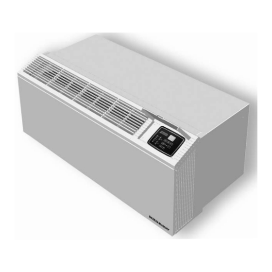
Page 5: Introduction
Introduction Figure 1: Model PDAA Unit with Touchpad Control (Shown with Subbase) Daikin McQuay offers the most complete line of PTAC products for new construction projects and exact replace- ments for our original Singer, Remington, American Air Filter and American Standard brand equipment, and models from other manufacturers. -
Page 6: Dimensional Data
Dimensional Data Figure 3: PDAA Chassis & Cabinet Dimensions 42" (1067mm) " 24" (610mm) " (145mm) (255mm) 1/2" (13mm) Flange Type " (439mm) " (506mm) Base Pan " (368mm) " (440mm) " (727mm) " (506mm) Fin Width 3/8" (Stamped) Louver 42"... -
Page 7: Wall Opening Requirements
Wall Opening Requirements Figure 5: Masonry Wall (Thick) Construction When roughing in the opening for the wall sleeve, make Room Side certain there is sufficient clearance from the walls and floor. Lintels (by others) The wall sleeve should be positioned a minimum of 5/8" in from the room side finished wall to accommodate the room cabinet. -
Page 8: Installing Subbase(S)
3. Insert leveling bolts into subbase bottom flange. Four (4) Installing Subbase(s) bolts are required if side extensions are used. Only two Electric Subbase (2) bolts are required if side extensions are not used. 4. Place the subbase on the floor and align its center line Note: An electrical subbase is optional for all 208V and 230V units. A subbase is required for all 265V units. -
Page 9: Hydronic Subbase
Hydronic Subbase Notes: Side channels are adjustable from 0" to 9-3/8" in A subbase is available as required with all hydronic units. length by inverting them. Side channels are predrilled This subbase measures 8" (203mm) in height and includes to allow infinite adjustment. the hydronic heating coil. Subbase shown with louvered front panel removed. Electrical and plumbing rough-in can be done through the Front panel is hinged to allow access to valve, coil, back of the hydronic heat section or through the openings filter & electrical junction box. -
Page 10: Hydronic Subbase - Plumbing And Electrical Connections
Hydronic Subbase – Plumbing and Electrical The electrical supply can also be roughed in to the subbase Electrical Connections heat section either through the holes provided in the base or Plumbing through the back. The coil supplied with the subbase heat section can be used The receptacle is shipped in a separate carton to be field with hot water or steam heating. -
Page 11: Installing Condensate Drain Kit(S)
3. Drill two (2) 5/32" pilot holes for the mounting screws. Installing Condensate Drain Kit(s) These holes can be located using the drain kit as a External Drain Kit pattern. 4. Assemble the drain kit as shown in Figure 11 Indoor Drain Kit securely fasten it to the wall sleeve with the screws provided. -
Page 12: Installing Wall Sleeve
Figure 12: External Drain Kit - installed after the cabinet/wall sleeve has been installed. Square Drain Holes 1/2" (13mm) O.D. Drain Tube Neoprene Sponge Gasket Alternate 6" Long, 1/2" O.D. Steel Mounting Plate Straight Copper Tube Note: Use of 6" straight drain tube will require modification of architectural louver. Installing Wall Sleeve Wall Sleeve Extension for Thick Wall Construction Types Considerations... -
Page 13: Installing Wall Sleeve Extension
Installing Wall Sleeve Extension Figure 14: Louver Frame Dimensions Wall sleeve extensions are shipped in a separate carton and tagged to match the proper unit. Be sure to check tagging of the extension against that of the unit. Install the wall sleeve extension as follows: 1. -
Page 14: Procedure
Procedure Anchoring The Wall Sleeve 1. Clean the opening of all debris that may interfere with Anchoring the wall sleeve in the opening is accomplished as installation. Figure shown in 2. If the unit is to be supplied with a subbase, install CAUTION subbase before installing wall sleeve. -
Page 15: Installing Basic Wall Sleeve
Figure 17: Frame and brick with electrical subbase Installing Basic Wall Sleeve Steel Lintel Frame and Brick Wall Construction Type (by others) A heavy-gauge, corrosion resistant wall sleeve is provided Outside for each unit. The wall sleeve is either shipped in a separate Louver "... -
Page 16: Panel Wall Construction Type
Figure 19: Frame and brick with hydronic subbase CAUTION Steel Lintel DO NOT drill holes in the bottom of the wall sleeve as it will (by others) cause leaks. Outdoor Louver 7. Where a subbase is used, secure wall sleeve to subbase with clips provided. -
Page 17: Thick Wall Construction Type
Figure 21: Panel wall construction with cord connection Thick Wall Construction Type Installation of wall sleeves for thick walls requires special "Louver Frame consideration. Table 2 should be used to determine the maxi- Outside Dimensions" on page Louver mum wall thickness allowed for the basic wall sleeve. For for details) thicker walls, wall sleeve exten sions are available from your representative. - Page 18 Table 2: Maximum Wall Thickness Figure 24: Thick wall construction with cord connection Maximum Wall Thickness Table 2 Louver Type Standard Hydronic 1/8"(3mm) Min. Subbase Subbase Subbase Caulk Steel Lintel 14"(356mm) "(241mm) Stamped "(333mm) Perimeter (by others) "(378mm) "(264mm) Architectural 14"(356mm) Outside 13-3/4"...
-
Page 19: Attaching Wall Sleeve To Subbase
• Overhangs that do not allow discharge air to rise Have your local Daikin McQuay representative evaluate • Installation of bug screen of any kind the application of special louvers or building facade treat-... -
Page 20: Installing Louver(S)
3. Check nameplate data on chassis to insure that the Installing Louver(s) correct job site distribution has been made with respect 1. Remove louver and mounting hardware from the to heating/cooling capacities. Generally, corner rooms shipping carton. require larger capacities. 2. -
Page 21: Equipment Start-Up
Form No. 13F-1206, located on page 22 Note: That unless otherwise specifically agreed to in writing, Daikin McQuay includes no field labor, start- up service or the like in the price of its equipment. After the equipment leaves the factory, it may become damaged or maladjusted during transportation or on the job. Sometimes wires are disconnected accidentally or fan motors move on their bases due to rough handling, causing fans to strike. -
Page 22: Ptac Startup Report-Audit
PTAC Startup Report–Audit Job Name __________________________________________ City ________________ G.O. # ____________ Installer __________________________________________________________________ Total No. of Units_____ Date of Final Inspection and Start-up ________________________________________ Unit Type □ □ Manufacturers’ Representative Name ___________________________________ APTAC 16 × 42 Type K □ □ APTAC 16 ×... -
Page 23: Controls
Controls Table 1: Keys and Indicators Labels ON/OFF, FAN SPEED, MODE Standard (Non-programmable) Digital 7 Push Buttons FAN MODE, SLEEP Touchpad Control Temp buttons: Figure 30: Standard Digital Touchpad ControlApplication Temp UP and for Temp DOWN 9 LED Indicators SLEEP, COOL, COOL/DRY, FAN, HEAT, HIGH, LOW, CYCLE, CONT. -
Page 24: Operation
Operation Fan Cycle Operation On a call for Heating or Cooling, the indoor fan and the Memory Recall heating source or the compressor will be activated. When the The digital control shall start with the last settings used prior call is satisfied and the heating source or the compressor is to power down. -
Page 25: Sequence Of Operation
Control Lockout Feature Cool Dry Mode The control is placed in a lockout mode of operation when Select the Cool Dry Mode when the standard Cool Mode Mode button is held pressed for 10 seconds. Display will does not provide sufficient dehumidification. In Cool Dry show “LC”... -
Page 26: Heat Mode
Figure 34: If 0°F < Ts - Ts < 2°F, operation will be in 2) Hot Keep Zone C In Hydronic Heat: When the water valve closes, the indoor fan will operate per the user mode (Constant or Cycle) and speed setting. Heat Fan Lock Out Control: When the unit is in the Heat Compressor Mode, but when hot water or steam is not available, it pre-... -
Page 27: Thermistor Error Codes And Conditions
The Display will show the upper operating limits first. The 7) Outdoor Air Sensor Reading default settings are Cool min. = 60°F and Heat max. = 85°F. To advance from Indoor Coil Sensor Reading to Outdoor Air Sensor Reading, press the Mode Button once. The display 4) Fresh Air Damper Control will show the Outdoor Air Sensor temperature. -
Page 28: Unit Protective Logic
Unit Protective Logic Temperature Limit Settings 1 To adjust the lower operating temperature limit (cool Compressor Minimum Run Time minimum set point) press and hold Fan Mode button For thermostat-controlled running cycles, the compressor and adjust the setting with Up or Down buttons. The will have a minimum run time of 90 seconds. -
Page 29: Premium (Programmable) Digital Touchpad Control Features
Premium (Programmable) Digital User Interface The user will by default control the Electronic Controller via Touchpad Control Features the touchpad. The user can select with a jumper for the unit to receive commands from a Remote Thermostat. LED with Program Table 3: Keys and Indicators Labels Setting ON/OFF, FAN SPEED, MODE,... -
Page 30: Premium (Programmable) Digital Touchpad Control
Adjust the time by pressing buttons. By AUTO Non-Programmable Mode: holding pressed buttons, time will change • Display shows both HEAT and COOL icons in 15 minutes increments or decrements respectively. • Temperature set point displays between the HEAT and AM and PM will show in rotation. - Page 31 To view the upper operating temperature limit (heat To advance to the next screen, press SLEEP ) button. Starting time will flash. Adjust the maximum set point) press MODE button. HEAT will starting time by pressing buttons. be displayed. An example of what can be displayed: DAY 1 8:00 MORN...
-
Page 32: Remote Wall Mounted Thermostats
W, Y, G to common (C), respectively. Therefore, if you are using existing solid-state thermostats, you may have to add loading resistors for your PTAC controls to work properly. Daikin McQuay thermostats do not require this modification. Page 32 of 48... -
Page 33: Wall-Mounted, 7, 5-2 & 5-1-1 Programmablethermostat
Standard Auto or Manual-Changeover ProgrammableThermostat Specs Two-Stage Heat/ Two-Stage Cool Specs Manual Changeover One-Stage Heat and Cool or Daikin McQuay Part No. 910116774 (1-Pk, White with One-Stage Heat Pump Wall Plate) Daikin McQuay Part No. 910116772 (1-Pk, White with Wall Plate) -
Page 34: Wireless Remote Control (Optional)
HVAC equipment, and communi- Functions the same as the SLEEP button on the cates with its thermostat using unlicensed 900 MHz, radio touchpad. frequency energy. Contact your local Daikin McQuay Repre- sentative for details. Mode buttons • Heat, Cool, Cool/Dry, Fan:... -
Page 35: Remote Mounted Thermostat Control Considerations
1. When wiring the low voltage plug and receptacle Remote Mounted Thermostat Control disconnect, provide enough wire to move harness out of Considerations the way for chassis removal. The Remote Thermostat can be any thermostat that can 2. If subbase is used, a small hole must be drilled and interface with an electronic thermostat via RCWYBG grommeted in the subbase front to allow passage of the terminals. -
Page 36: Premium (Programmable) Digital Control Board - Jumper Placement
Premium (Programmable) Digital 3– Jumper Placement to Select Controller Type: Control Board – Jumper Placement A– Place jumper across LUI to select unit mounted touchpad (Local User Interface). 1– Jumper Placement to Select System Module B– Place jumper across SLAVE to select SLAVE Control by (See Jumper Detail) A–... -
Page 37: Standard (Non-Programmable) Digital Control Board - Jumper Placement
Standard (Non-Programmable) 3– Jumper Placement to Select Controller Type: Digital Control Board – Jumper A– Place jumper across LUI to select unit mounted touchpad Placement (Local User Interface). B– Place jumper across T’STAT to select remote, wall 1– Jumper Placement to Select System Module (See mounted programmable, or non- programmable Jumper Detail) thermostat. -
Page 38: Digital Control Board With Standby Power - Wiring Diagram
If there is no need to run the motors at a separate voltage the Digital Control Board with Standby L1 = L1 STBY and L2 = L2 STBY. Therefore one voltage is Power – Wiring Diagram used to run all motors. The standby power connections, L1 STBY and L2 STBY are If the jumpers are accidentally cut, then the connections can meant to run the indoor motor at a separate voltage from the... -
Page 39: Digital Control Board Without Standby Power - Wiring Diagram
Digital Control Board without Standby Power – Wiring Diagram The standby power connections, L1 STBY and L2 STBY are meant to run the indoormotor at a separate voltage from the other motors, compressor and outdoor motor. When used as such, the jumpers, JH1 and JH2, must be cut. This renders L1 &... -
Page 40: Maintenance (Scheduled)
Rinse filter with hot water and a mild detergent. the outdoor louver. B. Daikin McQuay recommends that every year the chassis 2. In coastal areas, the units must have the corrosion be removed for a thorough checkup. This should be protection package to maintain the warranty coverage. -
Page 41: Recommended Spare Parts
Figure 41 illustrates the refrigeration cycle. The diagram shows what occurs in each component of a hermetically sealed system as used in all Daikin McQuay Air Conditioning equipment. The temperatures shown are typical of what they might be when the air entering the condenser (outdoor temperature) is 95°F, (350 C) and the... -
Page 42: Control Board
Fault and Protection Codes for Applied PTAC Control Board Fault code Description Cause for the fault Communication Error 1. Cable not plugged in properly on either LUI or relay board. 2. Defective cable. Missing Shunt The user configurable shunt for System Select, Control Select Off Fan Cycle, and/or Hydronic Valve is missing or not placed properly. -
Page 43: Solid State Digital Controls - Local User Interface Display Codes
Solid State Digital Controls – Local User Interface Display Codes Fault code Description Cause for the fault Auto Damper Control setup indicator damper is in "automatic" mode. Auto HP/E Control setup indicator heat pump electric is in automatic changeover mode (HP/E). Brown Out or Brown Out - Control monitors input voltage to prevent relay chattering. -
Page 44: Troubleshooting
Starting capacitor malfunctions (open circuited, short Replace. circuited or loss of capacity). Defective compressor motor (short circuited, open * Ship cooling chassis prepaid to nearest Daikin McQuay circuited, grounded). authorized warranty station. Blowers run on cool and compressor starts but stops Operation of overload device due to overloading com- Check voltage supply. - Page 45 Trouble Cause Cure Too much cooling. Thermostat set too low. Adjust. Defective thermostat Replace. 10. “Sweating.” Condensate drain from evaporator to condenser Remove obstructions to water flow. plugged. Insulating seals on equipment damaged. Adjust or replace. Evaporator blower motor not up to speed. Check for correct voltage.
- Page 48 ©2013 McQuay International (800) 432-1342 www.daikinmcQuay.com IM 934-5 / 8-13 Page 48 of 48...