Table of Contents
Advertisement
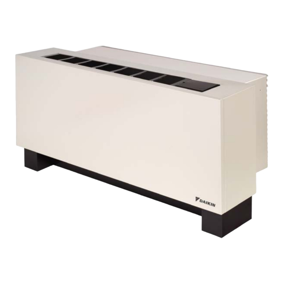
Applied Packaged Terminal Air Conditioner
16" x 42" PDAN with Top-Mounted Hydronic Heat with R-410A Refrigerant
Note: Installation and maintenance are to be performed only by qualified personnel who are familiar with local codes and
regulations and are experienced with this type of equipment. Caution: Sharp edges and coil surfaces are potential injury
hazards.
©2013 Daikin Applied • www.DaikinAP.com • (800) 432-1342
Installation & Maintenance Data
IM 938-4
Group: PTAC
Part Number: 910116723
Date: October 2013
Advertisement
Table of Contents

Related Manuals for Daikin IM 938-4


Summary of Contents for Daikin IM 938-4
- Page 1 Installation & Maintenance Data IM 938-4 Group: PTAC Part Number: 910116723 Date: October 2013 Applied Packaged Terminal Air Conditioner 16" x 42" PDAN with Top-Mounted Hydronic Heat with R-410A Refrigerant Note: Installation and maintenance are to be performed only by qualified personnel who are familiar with local codes and regulations and are experienced with this type of equipment. Caution: Sharp edges and coil surfaces are potential injury hazards. ©2013 Daikin Applied • www.DaikinAP.com • (800) 432-1342...
-
Page 2: Table Of Contents
Fault and Protection Codes for Applied PTAC/PTHP Unit Protective Logic ............20 Control Board..............36 Solid State Digital Controls – Local User Interface Display Room Freeze Protection ...........20 Codes ................37 Electrical Service Considerations........20 Electric Heat Unit ............20 Troubleshooting ..............38 IM 938-4 / Page 2 of 42... -
Page 3: Safety Information
Now that you have made an investment in modern, efficient Daikin equipment, its care and operation should be a high prior- ity. For training information on all Daikin HVAC products, please visit us at www.daikinmcquay.com and click on Training or phone 540-248-0711 and ask for the Training Department. -
Page 4: Daikin Model Pdan Product Nomenclature
T = Steam Top Mount (Normally Closed) A = Automatic (Required for Hydronic Heating) H = Hot Water Top Mount (Normally Open) A = Fresh Air Boost Fan Y = None M = Manual Y = No Damper IM 938-4 / Page 4 of 42... -
Page 5: Introduction
Introduction The self-contained refrigerant system delivers cooling to the Daikin offers the most complete line of PTAC and PTHP products for new construction projects and exact replace- desired space. Heating can be accomplished with electric resistance with hydronic (water or steam), hydronic with in-... -
Page 6: Dimensional Data
Rough-in (Typ. R.H. & L.H.) (406mm) (232mm) ⁄ " (140mm) 3" 7/8" (76mm) Min. (22mm) 3" Kickplate 3" (76mm) Min. (76mm) 7/8" (Removable Front) ⁄ ⁄ Kickplate Height " " (22mm) (33mm) (41mm) IM 938-4 / Page 6 of 42... -
Page 7: Wall Opening Requirements
Never secure the frame through the bottom as it may cause leaks. If the louver frame is to be installed in a panel wall, it should be installed at the same time as the wall sleeve. IM 938-4 / Page 7 of 42... -
Page 8: Wall Construction Types
Be careful not to plug the weep holes. Wall Sleeve Extension Note: When using recessed louver wall sleeve, level and (See "Installing Wall Splitters 16" x 42" plumb wall sleeve using the top and sides of the Sleeve Extension" on Cabinet/Wall Sleeve page 7) sleeve and the chassis slide rails. DO NOT level using the bottom of the wall sleeve as it has a built in pitch to drain. IM 938-4 / Page 8 of 42... - Page 9 3-1/2" Thick Optional 1-1/4" Batt Insulation Continuous Flange 16" Hydronic Heat Coil Section Cabinet Leveling Leg Optional Outdoor Side of Leveling Leg to Support Sleeve 6-3/8" Note: Given dimensions are standard. Notes: See "PDAN Chassis & Cabinet Dimensions" on page 6, for dimensions “D” and “B”. Dimension “X” is field determined or specified. Angle is factory welded at given dimension when option is designated. IM 938-4 / Page 9 of 42...
-
Page 10: Installing Wall Sleeve
10-3/4" (273mm) from the rear face of the standard wall sleeve. If no subbase is being 2. Daikin does not warrant the rain and water leakage employed, adequate support for the wall sleeve up to the resistance of its equipment when used with louvers by center of gravity must be provided at the job site. -
Page 11: Thick Wall Construction
7. Caulk the wall sleeve to the wall opening on both the in-side and outside perimeter using a resilient, nonhardening caulk such as silicone. Be careful not to plug the weep holes. IM 938-4 / Page 11 of 42... -
Page 12: Anchoring The Wall Sleeve
6. If the cooling chassis is not to be immediately installed, to cooling capacities. Generally, corner rooms require replace the weather panel. larger capacities. 3. Remove chassis from carton by pulling evenly on substantial portion of unit. IM 938-4 / Page 12 of 42... -
Page 13: Installing Heat Section
As shipped, the range is 60°F to 85°F. Factory Supplied 16. Replace the air filter and front panel. Holes (2) 17. Connect the low voltage valve wires with theMolex Damper Wall Sleeve Actuator connection to the valve. IM 938-4 / Page 13 of 42... -
Page 14: Installing Room Cabinet
Figure 23: Left-hand supply, right-hand return or Right- Figure 19: Right-hand supply, left-hand return hand supply, left-hand return Supply Return Return Return or Supply Supply Figure 20: Left-hand supply, right-hand return Supply Return IM 938-4 / Page 14 of 42... -
Page 15: Controls
The user will by default control the Electronic Controller via and Auto-Changeover models) and the control boards will the touchpad. The user can select with a jumper for the unit recognize the signals from them. to receive commands from a Remote Thermostat. IM 938-4 / Page 15 of 42... -
Page 16: Operation
Continuous, the “CONT” LED will be on and the fan Remote T’stat. Fan speed may be adjusted on will run continuously. When set for Cycle, the “CYCLE” the LUI (Touchpad). LED will be on and the fan will turn on at a call for heat or 4. The indoor fan is turned on when G signal is cooling. high. When there is no signal on G terminal then the indoor fan will be turned off. IM 938-4 / Page 16 of 42... -
Page 17: Sequence Of Operation
A changeover from Heat to Cool or another Mode will reset the Sleep Timer. The Sleep Function will be deactivated by pressing the power-on-reset or any button (except sleep) on the touchpad or the Remote Control. IM 938-4 / Page 17 of 42... -
Page 18: Heat Mode
Fan Mode and Speed setting. To set the Heat Maximum set point, press and hold Fan Speed button and adjust the setting with the Up or Down buttons. Maximum setting is 85°F. IM 938-4 / Page 18 of 42... -
Page 19: Thermistor Error Codes And Conditions
> 176°F for > 2s or To advance from Indoor Air Sensor Reading to Indoor Open or Close Coil Sensor Reading, press the Mode Button once. The display will show the indoor coil sensor temperature. IM 938-4 / Page 19 of 42... -
Page 20: Unit Protective Logic
National Electrical Code. The conditioner is marked with the minimum circuit ampacity and maximum fuse size. IM 938-4 / Page 20 of 42... -
Page 21: Equipment Start-Up
Correct voltage has been supplied to the equipment. The electrical plug from the control box has been inserted into the receptacle. During Start-up (applies only to standard equipment): Note: Direction of conditioner air may be adjusted by repositioning the discharge grille(s) to change airflow pattern in a room. The building superintendent or assistant manager should be requested to make any changes. IM 938-4 / Page 21 of 42... -
Page 22: Ptac/Pthp Startup Report-Audit
____________________________________________________________________________________________ ____________________________________________________________________________________________ ____________________________________________________________________________________________ ____________________________________________________________________________________________ Above System is in Proper Working Order FOR INTERNAL USE Release: SM ______________ Date CTS _____________ T________________ Sales Representative Signature Customer Signature Service Manager Approval Date Form No. 13F-1206 IM 938-4 / Page 22 of 42... -
Page 23: Premium (Programmable) Digital Touchpad Control Features
“AUTO”. The Auto Changeover control provides: • Auto changeover from heat to cool and vice versa • LED's from top down that read: Sleep, Cool, Auto, Fan, and Heat IM 938-4 / Page 23 of 42... -
Page 24: Premium (Programmable) Digital Touchpad Control
To set the time and day of the week, press FAN maximum set point) press MODE button. HEAT will MODE and FAN SPEED buttons simultaneously for be displayed. An example of what can be displayed: 5 seconds. Time will be displayed first: 9:45 IM 938-4 / Page 24 of 42... -
Page 25: Program Time Periods
However, the clock must be reset to the current time for the programmed daily settings to resume the correct schedule of operation. See Clock Set Menu instructions to reset the time and day of week. IM 938-4 / Page 25 of 42... -
Page 26: Remote Wall Mounted Thermostats
The remote thermostat can be any thermostat that can inter- One-Stage Heat Pump face with an electronic thermostat via RCBWYG terminals. Daikin Part No. 910116771 (1-Pk, White with Wall The Control Selection jumper must be in T’STAT position. Plate) During a call the remote thermostat will pass R back to the controller on a respective terminal. -
Page 27: Wall-Mounted, 7, 5-2 & 5-1-1 Programmablethermostat
Standard Auto or Manual-Changeover ProgrammableThermostat Specs Two-Stage Heat/ Two-Stage Cool Specs Manual Changeover One-Stage Heat and Cool or Daikin Part No. 910116774 (1-Pk, White with Wall Plate) One-Stage Heat Pump Daikin Part No. 910116772 (1-Pk, White with Wall Plate) Specifications Electrical Rating: •... -
Page 28: Wireless Remote Control (Optional)
Remote Mounted Thermostat Control Performs same function as the FAN SPEED button on the touchpad and allows user to select the specific speed using only one button. Notes: The remote must be aimed in a line of sight of the window in the upper right corner on the front panel, at less than a 45° angle from center of the window. T9000 Wireless Temperature Control IM 938-4 / Page 28 of 42... -
Page 29: Remote Mounted Thermostat Control Considerations
1. When wiring the low voltage plug and receptacle The number of secondary units that can be connected is limited to 32 units. Figure 33: Control Wiring to Allow Primary (Master) Secondary (Slave) Unit Connection Note: Connect the Remote Thermostat only to the Master Unit. IM 938-4 / Page 29 of 42... -
Page 30: Premium (Programmable) Digital Control Board - Jumper Placement
HFLO = Heat Fan Lockout Sensor = Outdoor Coil Sensor = Outdoor Air Sensor = Indoor Coil Sensor = Indoor Air Sensor = Local User Interface = Hydronic Valve = Reversing Valve = Electric Heat Contactor IM 938-4 / Page 30 of 42... -
Page 31: Standard (Non-Programmable) Digital Control Board - Jumper Placement
Wiring Diagram Legend Control Transformer Compressor Motor Indoor Fan Motor OFM = Outdoor Fan Motor Outdoor Coil Sensor Outdoor Air Sensor Indoor Coil Sensor Indoor Air Sensor Local User Interface Reversing Valve Electric Heat Contactor IM 938-4 / Page 31 of 42... -
Page 32: Digital Control Board With Standby Power - Wiring Diagram
Outdoor Coil Sensor Outdoor Air Sensor Indoor Coil Sensor Indoor Air Sensor Local User Interface Reversing Valve IR Receiver Board (AP7810) Indoor Motor Capacitor Outdoor Motor Capacitor Compressor Capacitor Motor Protector Note: The gray tinted areas in the wiring diagram; are options available only with the premium control board. For the latest drawing version refer to the wiring diagram located on the inside of the controls access panel of the unit. IM 938-4 / Page 32 of 42... -
Page 33: Digital Control Board Without Standby Power - Wiring Diagram
OAS = Outdoor Air Sensor Indoor Coil Sensor Indoor Air Sensor Local User Interface Reversing Valve IR Receiver Board (AP7810) Indoor Motor Capacitor Outdoor Motor Capacitor Compressor Capacitor Motor Protector Note: The gray tinted areas in the wiring diagram; are options available only with the premium control board. For the latest drawing version refer to the wiring diagram located on the inside of the controls access panel of the unit. IM 938-4 / Page 33 of 42... -
Page 34: Maintenance (Scheduled)
1. Avoid having lawn sprinkler heads spray directly in or on Rinse filter with hot water and a mild detergent. the outdoor louver. B. Daikin recommends that every year the chassis be 2. In coastal areas, the units must have the corrosion removed for a thorough checkup. This should be protection package to maintain the warranty coverage. -
Page 35: Recommended Spare Parts
Conditioned Air to Room Compressor stock of replacement parts is constantly replenished. Below is a list of the kinds of parts which Daikin recommends to be carried in stock together with the quantity of parts recom- mended per 100 incremental conditioners installed. -
Page 36: Fault And Protection Codes For Applied Ptac/Pthp Control Board
Indoor air temperature is 5 degrees above maximum setpoint limit. Protection feature and the displayed code are dismissed when indoor coil temperature rises above 50ºF. Low Room Temperature Indoor air temperature is 5 degrees below minimum setpoint limit. Low Ambient Lockout Outdoor air temperature is below 25ºF. IM 938-4 / Page 36 of 42... -
Page 37: Solid State Digital Controls - Local User Interface Display Codes
Outdoor Air Thermister Failure. Sensor missing or Short. Heat Fan Lock Out Heat Fan Lock Out Sensor Failure, missing, short on control board or heating medium >250°F. Sensor Check for installation/connection of HFLO sensor. Should be on coil return line. IM 938-4 / Page 37 of 42... -
Page 38: Troubleshooting
Starting capacitor malfunctions (open circuited, short Replace. circuited or loss of capacity). Defective compressor motor (short circuited, open * Ship cooling chassis prepaid to nearest Daikin autho- circuited, grounded). rized warranty station. Blowers run on cool and compressor starts but stops Operation of overload device due to overloading com- Check voltage supply. - Page 39 No power output on transformer secondary. Replace. Inoperative valve. 1) Steam valve N/C. 1) Temporarily lock valve open; replace. 2) Hot water valve N/C. 2) Replace. Notes: This guide was prepared with standard equipment in mind. If equipment is special, it may not be entirely applicable. If equipment is still in warranty. Notice: Before trying to correct the noise, determine its cause: conditioned air blower, compressor or condenser blower. Operate the conditioned air blowers only. If this doesn’t cause the noise, operate on cooling. Then disconnect one compressor lead. If the noise stops, the compressor is the source, If not, it is caused by the condenser blower. IM 938-4 / Page 39 of 42...
- Page 42 Daikin Training and Development Now that you have made an investment in modern, efficient Daikin equipment, its care should be a high priority. For training information on all Daikin HVAC products, please visit us at www.DaikinAP.com and click on training, or call 540-248-9646 and ask for the Training Department.