Lexmark X543 series Service Manual
Hide thumbs
Also See for X543 series:
- Service manual (359 pages) ,
- Quick reference (4 pages) ,
- User manual (258 pages)
Table of Contents
Advertisement
Quick Links
Advertisement
Table of Contents

Related Manuals for Lexmark X543 series


Summary of Contents for Lexmark X543 series
- Page 1 X543 - X544 series 7525xxx • Table of contents • Start diagnostics • Safety and notices • Trademarks • Index Lexmark and Lexmark with diamond design are trademarks of Lexmark International, Inc., registered in the United States and/or other countries.
- Page 2 Lexmark, Lexmark with diamond design, and MarkNet are trademarks of Lexmark International, Inc., registered in the United States and/or other countries. Optra Forms is a trademark of Lexmark International, Inc.
-
Page 3: Table Of Contents
Lexmark confidential until announce 7525xxx Table of contents Table of contents ............iii Notices and safety information . - Page 4 7525xxx Lexmark confidential until announce Fax specifications ..............1-18 Phone network connectivity .
- Page 5 Lexmark confidential until announce 7525xxx Print quality—residual image ..........2-57 Print quality—solid color page .
- Page 6 7525xxx Lexmark confidential until announce Flash Test ..............3-18 Printer Setup .
- Page 7 Lexmark confidential until announce 7525xxx MAC ..............3-38 NVRAM .
- Page 8 7525xxx Lexmark confidential until announce Autocompensator mechanism (ACM)—standard tray removal ......4-12 Bin full sensor ..............4-15 Controller board removal .
- Page 9 Lexmark confidential until announce 7525xxx Connectors ..............5-5 HVPS .
- Page 10 7525xxx Lexmark confidential until announce Service Manual...
-
Page 11: Notices And Safety Information
Lexmark confidential until announce 7525xxx Notices and safety information The following laser notice labels may be affixed to this printer. Laser notice The printer is certified in the U.S. to conform to the requirements of DHHS 21 CFR Subchapter J for Class I (1) laser products, and elsewhere is certified as a Class I laser product conforming to the requirements of IEC 60825-1. - Page 12 7525xxx Lexmark confidential until announce Avisos sobre el láser Se certifica que, en los EE.UU., esta impresora cumple los requisitos para los productos láser de Clase I (1) establecidos en el subcapítulo J de la norma CFR 21 del DHHS (Departamento de Sanidad y Servicios) y, en los demás países, reúne todas las condiciones expuestas en la norma IEC 60825-1 para productos láser de...
- Page 13 Lexmark confidential until announce 7525xxx Laserilmoitus Tämä tulostin on sertifioitu Yhdysvalloissa DHHS 21 CFR Subchapter J -standardin mukaiseksi luokan I (1) - lasertuotteeksi ja muualla IEC 60825-1 -standardin mukaiseksi luokan I lasertuotteeksi. Luokan I lasertuotteita ei pidetä haitallisina. Tulostimen sisällä on luokan IIIb (3b) laser, joka on nimellisteholtaan 5 mW:n galliumarsenidilaser ja toimii 770 - 795 nanometrin aallonpituuksilla.
- Page 14 7525xxx Lexmark confidential until announce Avís sobre el Làser Segons ha estat certificat als Estats Units, aquesta impressora compleix els requisits de DHHS 21 CFR, apartat J, pels productes làser de classe I (1), i segons ha estat certificat en altres llocs, és un producte làser de classe I que compleix els requisits d’IEC 60825-1.
- Page 15 Lexmark confidential until announce 7525xxx Notices and safety information...
- Page 16 7525xxx Lexmark confidential until announce Service Manual...
-
Page 17: Lithium Warning
Lexmark confidential until announce 7525xxx Lithium warning CAUTION This product contains a lithium battery. THERE IS A RISK OF EXPLOSION IF THE BATTERY IS REPLACED BY AN INCORRECT TYPE. Discard used batteries according to the battery manufacturer’s instructions and local regulations. - Page 18 7525xxx Lexmark confidential until announce xviii Service Manual...
- Page 19 Lexmark confidential until announce 7525xxx Sicherheitshinweise • Die Sicherheit dieses Produkts basiert auf Tests und Zulassungen des ursprünglichen Modells und bestimmter Bauteile. Bei Verwendung nicht genehmigter Ersatzteile wird vom Hersteller keine Verantwortung oder Haftung für die Sicherheit übernommen. • Die Wartungsinformationen für dieses Produkt sind ausschließlich für die Verwendung durch einen Wartungsfachmann bestimmt.
- Page 20 7525xxx Lexmark confidential until announce Informació de Seguretat • La seguretat d'aquest producte es basa en l'avaluació i aprovació del disseny original i els components específics. El fabricant no es fa responsable de les qüestions de seguretat si s'utilitzen peces de recanvi no autoritzades.
-
Page 21: Preface
Lexmark confidential until announce 7525xxx Preface This manual contains maintenance procedures for service personnel. It is divided into the following chapters: General information contains a general description of the printer and the maintenance approach used to repair it. Special tools and test equipment, as well as general environmental and safety instructions, are discussed. - Page 22 7525xxx Lexmark confidential until announce xxii Service Manual...
-
Page 23: General Information
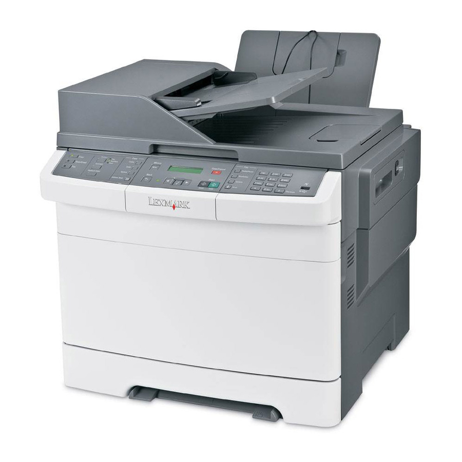
7525xxx 1. General information The Lexmark™ X54x series are color laser MFPs that combine print, scan, copy, and fax functions. The X54x series are the ideal MFPs for presentations, business graphics, line art, and text. They use laser diode electrophotographic technology to deliver remarkable quality print images and text. The scan and copy functions work with A4, letter, and legal (ADF only) size paper. -
Page 24: Options And Features
7525xxx Lexmark confidential until announce Options and features Certain options are available on selected printer models only. Available options include: • 650-Sheet Duo Drawer—a 550-sheet drawer with a 100-sheet multipurpose feeder (MP Feeder). • Additional memory—One 128, 256, or 512MB memory card may be added. -
Page 25: Print Quality
Lexmark confidential until announce 7525xxx Print quality During the life of the printer, components are subject to wear based on usage. Printers continuously operating at or near the maximum duty cycle may require service for replacement of these components to ensure high- quality printing and good performance throughout the life of the printer. -
Page 26: Operating Modes
7525xxx Lexmark confidential until announce Operating modes Mode Description Normal Factory default Quiet Designed for customers where noise levels are a very important factor. • Print quality is maintained at factory default level. • Speed is reduced. Eco-mode Designed for customers where the environment is a key factor. -
Page 27: Dimensions
100 mm (3.9 in.) Left side 100 mm (3.9 in.) Above 360 mm (14 in.)* * Add 133 mm (5.2 in.) to the top if you want to add an optional 650-sheet Duo Drawer (Lexmark X54x models only). General information... -
Page 28: Power And Electrical Specifications
7525xxx Lexmark confidential until announce Power and electrical specifications The following table specified nominal average power requirements for the base printer configurations. All power levels are shown in Watts (W). Maximum current is given in Amperes (A). Lexmark Printing states... -
Page 29: Acoustics
Lexmark confidential until announce 7525xxx Acoustics All acoustic measurements are made in accordance with ISO 7779-1999 and reported in conformance with ISO9296:1988-04-15. 1-Meter average sound Operating mode pressure at 4800 CQ Lexmark Lexmark X543 X544 Printing (simplex mono) 46 dBA... -
Page 30: Media Handling
7525xxx Lexmark confidential until announce Media handling Input and output sources Sheet numbers are assuming 20 lb. Lexmark X544dw, Lexmark X543 Lexmark X544n xerographic paper X544dn, X544dtn Standard input sources Standard input tray (250-sheet tray) 250 sheets 250 sheets 250 sheets... -
Page 31: Media Input Size Specifications
Lexmark confidential until announce 7525xxx Media input size specifications ✔ —Supported without size sensing ✘ —Not supported Input source ✔ ✔ ✔ ✔ ✔ A4 210 x 297mm ✘ ✔ ✔ ✔ ✔ 148 x 210mm ✘ ✘ ✔ ✘... -
Page 32: Media Input Type Specifications
7525xxx Lexmark confidential until announce ✔ —Supported without size sensing ✘ —Not supported Input source ✘ ✘ ✘ ✔ ✔ B5 Envelope ✘ ✘ ✘ ✔ ✔ Other envelope Length: 98.4–431.8mm (3.8–17 in.) Width: 89–297mm (3.5–11.7 in.) The MP feeder runs slower if A5, statement, B5, or envelope are loaded. -
Page 33: Media Output Size And Type
Lexmark confidential until announce 7525xxx ✔ —Supported ✘ —Not supported Input type ✔ ✔ ✔ ✔ ✔ Colored paper ✔ ✔ ✔ ✔ ✔ Light paper ✔ ✔ ✔ ✔ ✔ Heavy paper ✔ ✔ ✔ ✔ ✔ Rough or cotton ✔... -
Page 34: Index
(16–28 pound) grain long bond. The duplex unit does not support card stock, transparencies, envelopes, and labels. Lexmark transparency part numbers 12A8240, and 12A8241 are supported from the standard tray, manual slot and the multipurpose feeder. Paper 90 to 104.9 g/m (23.9 to 27.8 lb) must be printed with Paper Type set to Heavy Paper. -
Page 35: Media Guidelines
Lexmark confidential until announce 7525xxx Media guidelines Paper characteristics The following paper characteristics affect print quality and reliability. Consider these characteristics when evaluating new paper stock. • Weight—The printer can automatically feed paper weights from 60 to 176 g/m (16 to 47 lb bond) grain long. -
Page 36: Selecting Paper
US fed as well as non-recycled paper. However, no blanket statement can be made that all recycled paper will feed well. Lexmark consistently tests its printers with recycled paper (20–100% post-consumer waste) and a variety of test paper from around the world, using chamber tests for different temperature and humidity conditions. - Page 37 Lexmark confidential until announce 7525xxx Recycled paper, paper of lower weight (<60 g/m [16 lb bond]) and/or lower caliper (<3.8 mils [0.1 mm]), and paper that is cut grain-short for portrait (or short-edge) fed printers may have lower bending resistance than is required for reliable paper feeding.
-
Page 38: Digital Imaging Specifications
7525xxx Lexmark confidential until announce Digital imaging specifications General specifications ADF Scan speed Simplex ADF - Up to 25 ppm Duplex ADF - Up to 35 ppm (page sides) ADF Document handling ADF input capacity - 50 sheets. ADF output capacity - 50 sheets. -
Page 39: Scan And Copy Specific Specifications
Scan Resolutions • Optical - 600 dpi (Local Twain only) • Enhanced (vial Lexmark Scan Center) - 1200 X 1200 dpi, 2400 X 2400 dpi, 4800 X 4800 dpi, 9600 X 9600 dpi, 19200 X 19200 dpi Output resolutions •... -
Page 40: Fax Specifications
7525xxx Lexmark confidential until announce Fax specifications Phone network connectivity Phone networks types supported PSTN or analog PABX (RJ-11) ITU COMPATIBILITY Group 3/ECM Standard Resolution 8 x 3.85 pels/mm (200X100dpi) (204x98) Fine 8 x 7.7 pels/mm (200X200dpi) (204x196) Superfine 11.8 x 11.8 pels/mm(300x300 dpi) (204x391) Ultrafine 15.7 x 15.7 pels/mm (400x400 dpi) (408x391) -
Page 41: Tools Required For Service
Lexmark confidential until announce 7525xxx Tools required for service Flat-blade screwdrivers, various sizes #1 Phillips screwdriver, magnetic #2 Phillips screwdriver, magnetic #2 Phillips screwdriver, magnetic short-blade 7/32 inch (5.5 mm) open-end wrench 7.0 mm nut driver Needlenose pliers Diagonal side cutters... -
Page 42: Acronyms
7525xxx Lexmark confidential until announce Acronyms. Alternating Current Autocompensator Mechanism (or paper feed) Automatic document feeder Analog front end All-In-One Automatic Paper Size ASIC Application Specific Integrated Circuit BLDC Brushless DC Motor Black Only Retract Belt up down Cyan Charge-Couple Device... - Page 43 Lexmark confidential until announce 7525xxx High voltage unit Hertz INTL International Internal Tray Card Image Transfer Unit Black (Key) Local area network LASER Light amplification by stimulated emission of radiation Liquid crystal display Liquid Crystal Module Laser Diode Light emitting diode...
- Page 44 7525xxx Lexmark confidential until announce Pulse Width Modulation Random access memory RFID Radio frequency identification Relative humidity Raster image processor Read-only memory Read-only storage Revolutions Per Minute Scanner Control Card SDRAM Synchronous Dynamic Random Access Memory Short edge feed SIMM...
-
Page 45: Diagnostic Information
Lexmark confidential until announce 7525xxx 2. Diagnostic information Start CAUTION Unplug the power cord from the electrical outlet before you connect or disconnect any cable or electronic board or assembly for personal safety and to prevent damage to the printer. -
Page 46: Por (Power-On Reset) Sequence
7525xxx Lexmark confidential until announce POR (Power-On Reset) sequence The following is an example of the events that occur during the POR sequence for the base machine with no paper-handling options installed. When you turn the printer on, it performs a Power-On Self Test. Check for correct POST functioning of the base printer by observing the following: The LED turns on. -
Page 47: Symptom Tables
Lexmark confidential until announce 7525xxx Symptom tables Printer symptom table Symptom Action Dead printer Go to “Dead printer service check” on page 2-37. Operator panel—one or more buttons do Go to “One or more operator panel buttons fail” on not work. -
Page 48: Scan / Fax / Copy Symptom Table
7525xxx Lexmark confidential until announce Scan / fax / copy symptom table Symptom Action 840.xx scanner error Go to “840.xx service check” on page 2-63. ADF won’t duplex (Duplex ADF only) Go to “ADF Duplex service check” on page 2-69. -
Page 49: Print Quality Symptom Table
Lexmark confidential until announce 7525xxx Print quality symptom table Symptom Action Background Go to “Print quality—background” on page 2-51. Blank page Go to “Print quality—blank page” on page 2-52. Blurred or fuzzy print Go to “Print quality—blurred or fuzzy print” on page 2-54. -
Page 50: Error Codes And Messages
7525xxx Lexmark confidential until announce Error codes and messages User status and attendance messages User status and attendance messages User primary message Explanation Calibrating The printer is performing a color adjustment. Close Door Message clears when upper and lower doors are closed. - Page 51 Lexmark confidential until announce 7525xxx User status and attendance messages (continued) User primary message Explanation Load Manual Printer does not detect media meeting the description <custom string> in the single <custom string> sheet feeder (manual feeder). The following actions can be taken: •...
- Page 52 7525xxx Lexmark confidential until announce User status and attendance messages (continued) User primary message Explanation 31.xx Defective <color> The specified cartridge is defective. Try one of the following: cartridge • Open and close the top cover. • Remove and re-install the cartridge(s). Listen for the click to ensure the cartridge is installed properly.
- Page 53 Lexmark confidential until announce 7525xxx User status and attendance messages (continued) User primary message Explanation 37 Insufficient memory This message is displayed when insufficient printer memory is available to perform for flash defragment Flash Memory Defragment operation. operation This message appears prior to the actual start of the defragment operation.
- Page 54 7525xxx Lexmark confidential until announce User status and attendance messages (continued) User primary message Explanation 53 Unformatted Flash press Select ( to clear the message and continue printing. You must format the flash memory before you can store any resources on it. If the error message remains, the flash memory may be defective and require replacing.
- Page 55 Lexmark confidential until announce 7525xxx User status and attendance messages (continued) User primary message Explanation 88 <color> Cartridge The term <color> includes black, cyan, magenta, and yellow. Early Warning • Replace the toner cartridge and press Select ( to clear the message and continue printing.
-
Page 56: Paper Jam Messages
7525xxx Lexmark confidential until announce Paper Jam messages Paper jam messages (2xx) Error code Description Action 2xx paper jams 200.xx Paper Jam A single page of media jam at the input Remove the tray1 unit, open the front door, Check <area>... - Page 57 Lexmark confidential until announce 7525xxx Paper jam messages (2xx) (continued) Error code Description Action 290.20 Scanner This message occurs when paper is Remove original documents from the ADF. Static Jam-Paper detected in the ADF during a POR, or Present when the MFP is starting up.
-
Page 58: Service Error Messages
7525xxx Lexmark confidential until announce Service error messages Service error messages (1XX, 8XX and 9xx) Error code Description Action 106.xx Service Yellow printhead error. Perform a POR. If the problem persists, go Yellow Printhead “Printhead service check” on page 2-59. - Page 59 Lexmark confidential until announce 7525xxx Service error messages (1XX, 8XX and 9xx) (continued) Error code Description Action 107.07 Service The cyan printhead thermistor is Perform a POR. If the problem persists, go Cyan Printhead shorted to ground. “Printhead service check” on page 2-59.
- Page 60 7525xxx Lexmark confidential until announce Service error messages (1XX, 8XX and 9xx) (continued) Error code Description Action 109.05 Service Failure reading NVRAM from Perform a POR. If the problem persists, go Black Printhead printhead. “Printhead service check” on page 2-59.
- Page 61 Lexmark confidential until announce 7525xxx Service error messages (1XX, 8XX and 9xx) (continued) Error code Description Action 122.16 Service EWC Error—Estimated power is at or Go to “Fuser service check” on Fuser Error above maximum power. page 2-41. 141.xx Service Staging motor error.
- Page 62 7525xxx Lexmark confidential until announce Service error messages (1XX, 8XX and 9xx) (continued) Error code Description Action 152.04 Service Timeout waiting for SAP BLDC motor Go to “Main drive gear assembly (EP Cyan Cartridge Motor drive) service check” on page 2-43.
- Page 63 Lexmark confidential until announce 7525xxx Service error messages (1XX, 8XX and 9xx) (continued) Error code Description Action 154.05 Service Lost lock for motor. Go to “Main drive gear assembly (EP Yellow Cartridge drive) service check” on page 2-43. Motor 154.06 Service Excessive SAP BLDC PWM.
- Page 64 7525xxx Lexmark confidential until announce Service error messages (1XX, 8XX and 9xx) (continued) Error code Description Action Front scan module cable failure or SCC CCD channel failure. Check each card failure channel(mono, R, G, B) for identical values indicating bad cable and/or SCC card.
- Page 65 Lexmark confidential until announce 7525xxx Service error messages (1XX, 8XX and 9xx) (continued) Error code Description Action Fax Storage The amount of flash storage available on the device is too small. Note: The NAND Flash partition can shrink as bit failures cause blocks to be invalidated.
- Page 66 7525xxx Lexmark confidential until announce Service error messages (1XX, 8XX and 9xx) (continued) Error code Description Action 914.xx Service The DC pick has no encoder feedback. Go to “Autocompensator mechanism PC Pick Motor service check” on page 2-35 917.xx Service...
- Page 67 Lexmark confidential until announce 7525xxx Service error messages (1XX, 8XX and 9xx) (continued) Error code Description Action 940.xx Service A RIP to engine communication failure. LV Power Supply The zero crossing signal used for fuser control in the low-voltage (LV) power...
- Page 68 7525xxx Lexmark confidential until announce Service error messages (1XX, 8XX and 9xx) (continued) Error code Description Action 955.xx Service The Code ROM or NAND flash failed Code CRC <loc> the Cyclic Redundancy Check (CRC) check or the NAND experienced an uncorrectible multi-bit failure.
- Page 69 Lexmark confidential until announce 7525xxx Service error messages (1XX, 8XX and 9xx) (continued) Error code Description Action 959.22 Service Challenge Secret Failure. ASIC/SP mismatch System Board Replace controller board. See“Controller board removal” on page 4-16. 959.23 Service Hardware control self test failure during Replace controller board.
- Page 70 7525xxx Lexmark confidential until announce Service error messages (1XX, 8XX and 9xx) (continued) Error code Description Action 978.xx Service Bad checksum while programming Check the following: Standard Network network port. • Make sure you have downloaded the code in binary mode, not ASCII.
- Page 71 Lexmark confidential until announce 7525xxx Service error messages (1XX, 8XX and 9xx) (continued) Error code Description Action 990.xx Service This error message indicates that an <device> equipment check condition has occurred in the specified device, but the device is unable to identify the exact component failure.
-
Page 72: Fax Error Log Codes
7525xxx Lexmark confidential until announce Fax error log codes Fax error log codes Error code Description Action No error occurred during fax No action needed transmission Error occurred when transmitting • Check line quality. • Select a lower ‘Max Speed’. - Page 73 Lexmark confidential until announce 7525xxx Fax error log codes (continued) Error code Description Action T5 Timeout occurred when transmitting • Check line quality. image data to remote fax device. • Adjust ‘Transmit Level’. • Select a lower ‘Max Speed’value under Fax Send settings.
- Page 74 7525xxx Lexmark confidential until announce Fax error log codes (continued) Error code Description Action Failure to transmit training successfully • Select a lower “Max Speed” under Fax in V17, V29 terminal modulation Send settings. schemes. • Adjust the “Transmit Level”.
- Page 75 Lexmark confidential until announce 7525xxx Fax error log codes (continued) Error code Description Action Modem detected a digital line Verify the MFP is connected to an analog connection. line. See“Fax transmission service check” on page 2-71. Phone line was disconnected Restore phone line connection.
-
Page 76: Service Checks
7525xxx Lexmark confidential until announce Service checks Autocompensator mechanism service check Step Questions / actions Turn the printer off, and then remove the rear Go to step 3. Properly connect the cables, shield. See “Rear shield removal” on and POR the printer. -
Page 77: 925.01-Fan Error Service Check
Lexmark confidential until announce 7525xxx Step Questions / actions Turn the printer on and check following values Replace the fuser assembly. Replace the controller on JFUSES1. “Fuser assembly board. See “Controller removal” on page 4-19. board removal” on JFUSES1 page 4-16. -
Page 78: 930.Xx-935.Xx-Printhead Errors Service Check
7525xxx Lexmark confidential until announce 930.xx–935.xx—Printhead errors service check Step Questions / actions Turn the printer off, and remove the rear shield. Replace the printhead. See Go to step 2. “Rear shield removal” on page 4-7. “Printhead removal” on Check the cables connected at JMIRR1 and page 4-42. -
Page 79: 950.Xx Eprom Mismatch Failure Service Check
Lexmark confidential until announce 7525xxx 950.xx EPROM mismatch failure service check Warning: Replace one of the following components, and perform a POR before replacing a second component. Never replace both of the components without performing a POR after installing each one, or the printer will be rendered inoperable: •... -
Page 80: Bin Full Sensor Service Check
7525xxx Lexmark confidential until announce Bin full sensor service check Step Questions / actions Is the input sensor dislodged or damaged? Repair or replace the Go to step 2. autocompensator mechanism. See “Autocompensator mechanism (ACM)— standard tray removal” on page 4-12. -
Page 81: Dead Printer Service Check
Lexmark confidential until announce 7525xxx Dead printer service check A dead printer is a condition where the display is blank, the LED on the operator panel is off, the fan does not turn, no motors turn, and the fuser does not heat. -
Page 82: Duplex/Manual Feed Sensor (S1) Service Check
7525xxx Lexmark confidential until announce Duplex/manual feed sensor (S1) service check Note: Before performing this service check, ensure that the printer is on a hard level surface. Step Questions / actions Enter Diagnostics Menu (turn the printer off, Go to step 2. -
Page 83: Front Door Sensor Or Switches Service Check
Lexmark confidential until announce 7525xxx Front door sensor or switches service check Step Questions / actions Enter Diagnostics Menu (turn the printer off, press Sensor, toner door, and Go to step 2. and hold , turn the printer on, and then right doors are OK. -
Page 84: Fuser Exit Sensor Service Check
7525xxx Lexmark confidential until announce Fuser exit sensor service check Step Questions / actions Enter Diagnostics Menu (turn the printer off, Correct the sensor or Go to step 2. press and hold , turn the printer on, replace it. See “”... -
Page 85: Fuser Service Check
Lexmark confidential until announce 7525xxx Fuser service check Step Questions / actions Some low-voltage power supply FRUs have a Check the switch on the side Go to step 2. voltage selector switch. If it does, the switch of the LVPS to verify the needs to be set to the correct voltage for your correct voltage is set. -
Page 86: Input Sensor (S2) Service Check
7525xxx Lexmark confidential until announce Input sensor (S2) service check The Input sensor (S2) is part of the ACM FRU. Step Questions / actions Enter Diagnostics Menu (turn the printer off, Replace the Go to step 2. press and hold... -
Page 87: Main Drive Gear Assembly (Ep Drive) Service Check
Lexmark confidential until announce 7525xxx Main drive gear assembly (EP drive) service check Step Questions / actions Turn the printer off, and remove the rear shield. Replace the JCARTB1 Go to step 2. “Rear shield removal” on page 4-7. cable. -
Page 88: Operator Panel Service Check
7525xxx Lexmark confidential until announce Operator panel service check Warning: Replace one of the following components, and perform a POR before replacing a second component. Never replace both of the components without performing a POR after installing each one, or the printer will be rendered inoperable: •... -
Page 89: Operator Panel Display Blank, Printer Beeps Five Times And Pauses
Lexmark confidential until announce 7525xxx Step Questions / actions Turn the printer off, and remove the rear shield. Go to step 3. Replace the controller “Rear shield removal” on page 4-7. board. See “Controller Disconnect the operator panel assembly cable board removal”... -
Page 90: Operator Panel Displays All Diamonds, No Beeps
7525xxx Lexmark confidential until announce Operator panel displays all diamonds, no beeps Step Questions / actions Turn off the printer, and remove the rear shield. Go to step 2. Replace the controller “Rear shield removal” on page 4-7. board. See “Controller... -
Page 91: Operator Panel Display Is Dim And Unchanging
Lexmark confidential until announce 7525xxx Operator panel display is dim and unchanging Step Questions / actions Turn off the printer, and remove the rear shield. Go to step 2. Replace the controller “Rear shield removal” on page 4-7. board. See “Controller... -
Page 92: Networking Service Check
Have the network administrator verify that the device is using the correct SSID, and wireless security protocols. For more network troubleshooting information, consult the Lexmark Network Setup Guide. Step... - Page 93 Lexmark confidential until announce 7525xxx Step Questions / actions Try using a different ethernet cable. Problem resolved Go to step 14. Did this remedy the situation? Have the network administrator check the Replace the controller Contact the network network drop for activity.
-
Page 94: Print Quality Service Check
7525xxx Lexmark confidential until announce Print quality service check Note: This symptom may require replacement of one or more CRUs (Customer Replaceable Units) designated as supplies or maintenance items, which are the responsibility of the customer. With the customer's permission, you may need to install a developer (toner) cartridge or photo conductor unit. -
Page 95: Print Quality-Background
7525xxx Print quality—background Service tip: Some background problems can be caused by rough papers, non-Lexmark toner cartridges or if the media texture is set to the rough setting. Some slick or coated papers may also cause background problems. Some problems occur with printers that run a large amount of graphics in a humid environment. -
Page 96: Print Quality-Blank Page
7525xxx Lexmark confidential until announce Step Questions / actions Clean the printhead. Problem resolved. Replace the printhead. See “Printhead removal” on Does this fix the problem? page 4-42. Print quality—blank page Step Questions / actions Is all the packing material for the imaging unit Go to step 2. - Page 97 Lexmark confidential until announce 7525xxx Step Questions / actions Enter the Diagnostics Menu (turn the printer Go to step 5. Replace the Main drive gear off, press and hold , turn the printer assembly. See “Main drive on, and release the buttons when installed...
-
Page 98: Print Quality-Blurred Or Fuzzy Print
7525xxx Lexmark confidential until announce Print quality—blurred or fuzzy print Run the automatic alignment. The TPS sensor may be damaged. To run Reset Color Cal: Enter the Diagnostics Menu. (Turn the printer off, press and hold , turn the printer on, and release the buttons when installed memory and processor speed displays. -
Page 99: Print Quality-Horizontal Line
Lexmark confidential until announce 7525xxx Print quality—horizontal line Either the photoconductor unit or one of the developer units that make up the imaging unit is defective. Remove and inspect the imaging unit. Replace the damaged part of the imaging unit. See “Imaging unit (IU) removal”... -
Page 100: Print Quality-Narrow Vertical Line
7525xxx Lexmark confidential until announce Print quality—narrow vertical line ABCDE ABCDE ABCDE Step Questions / actions Replace the photoconductor unit. See Problem solved. Replace the developer unit. “Developer unit “Imaging unit (IU) removal” on page 4-28. removal” on page 4-30 Print quality—random marks... -
Page 101: Print Quality-Residual Image
Lexmark confidential until announce 7525xxx Print quality—residual image Service tip: Install a new print cartridge, if available, before doing this service check. Residual image can be caused by the photoconductor, cleaning blade, and other parts ABCDE inside the print cartridge. -
Page 102: Print Quality-Solid Color Page
7525xxx Lexmark confidential until announce Print quality—solid color page Service tip: A solid color page is generally caused by a problem in the high-voltage controller or an incorrect high voltage in the printing process resulting in toner development on the entire photoconductor drum. -
Page 103: Printhead Service Check
Lexmark confidential until announce 7525xxx Printhead service check This service check includes the following errors: Error codes Color 106.xx Yellow 107.xx Cyan 108.xx Magenta 109.xx Black Step Questions / actions Turn the printer off, and remove the rear shield. Replace the printhead. See Go to step 2. -
Page 104: Toner Meter Cycle (Tmc) Card
7525xxx Lexmark confidential until announce Toner meter cycle (TMC) card Step Questions / actions Perform the Base Sensor Test: Replace the toner cartridge. Replace the toner meter cycle (TMC) card. See 1. Enter Diagnostics menu (turn off the “Toner meter cycle (TMC) -
Page 105: Transfer Roll Service Check
Lexmark confidential until announce 7525xxx Transfer roll service check Step Questions / actions Remove the ITU. See “Image transfer unit Replace the ITU. See Problem resolved. (ITU)” on page 4-25. Check the contacts “Image transfer unit (ITU)” between the HVPS and the ITU. Clean the on page 4-25. -
Page 106: Tray 1 Sensor Service Check
7525xxx Lexmark confidential until announce Tray 1 sensor service check Step Questions / actions When the printer is in Ready state, pull the Go to step 2. Go to step 4. standard tray out. The display should indicate Tray 1 Missing. Insert the tray. -
Page 107: 840.Xx Service Check
Lexmark confidential until announce 7525xxx Scanner / Copy / Fax service checks 840.xx service check Step Questions / actions POR the machine into configuration mode. Go to step 2. Stop. Problem resolved. Go to the disable scanner menu item. See “Disable Scanner”... - Page 108 7525xxx Lexmark confidential until announce Step Questions / actions Replace the ADF unit. See “Duplex ADF Go to step 8. Stop. Problem solved. removal” on page 4-63or “Simplex ADF removal” on page 4-64. POR the machine into configuration mode. Go to the disable scanner menu item.
-
Page 109: Black Or Blank Page Copy Service Check
Lexmark confidential until announce 7525xxx Black or blank page copy service check Step Questions / actions Print a menu page, or a page from the host. “Print quality—solid Go to step 2. Is the page black? color page” on page 2-58 Is the copy an ADF scan? Go to step 3. -
Page 110: Flatbed Home Position Service Check
7525xxx Lexmark confidential until announce Flatbed home position service check Step Questions / actions POR the MFP. Does the CCD move and Problem solved. Go to step 2. return to the home position? Perform the home position sensor test. Go Go to step 3. -
Page 111: Adf Cover Open Service Check
Lexmark confidential until announce 7525xxx ADF cover open service check Step Questions / actions Is the ADF cover properly closed Go to step 3. Go to step 2. Close the ADF cover. Issue resolved Go to step 3. Does the problem go away? Perform the ADF cover open sensor test. -
Page 112: Adf Paper Jam Service Check
7525xxx Lexmark confidential until announce ADF paper jam service check Note: This service check should be used if the paper feeds and jams in the ADF. If the paper is not feeding into the ADF see “ADF feed errors service check” on page 2-69. -
Page 113: Adf Feed Errors Service Check
Lexmark confidential until announce 7525xxx ADF feed errors service check Step Questions / actions If the ADF is multi-feeding, check for Clean them with a lint free Replace the separator pad and dirt on the ADF separator pad and cloth and isopropyl alcohol. -
Page 114: Modem / Fax Card Service Check
7525xxx Lexmark confidential until announce Check all the connections on the ADF Go to step 4 Properly connect all the relay card. Are they properly connections. connected? Check the ADF cable to ensure it is Go to step 5. Properly connect the ADF cable properly connected to CN 15 on the to its connections. -
Page 115: Fax Transmission Service Check
Lexmark confidential until announce 7525xxx Fax transmission service check Note: Before performing this service check, verify that the correct country code for the MFP is selected. This setting must match the country in which the MFP is used to transmit and receive faxes. If the setting is wrong, the modem settings can be changed in the Fax/SE menu. - Page 116 7525xxx Lexmark confidential until announce Step Questions / actions Adjust the “Transmit Level” setting in the SE Stop. Problem resolved. Go to your second-level of menu. press **411 to enter the SE menu, support. See “Escalating a enter Modem settings, and select “Transmit fax issue to second-level Level”.
-
Page 117: Fax Reception Service Check
Lexmark confidential until announce 7525xxx Fax reception service check Step Questions / actions Is the phone line properly connected to the Go to step 2. Go to step 3. modem card and the wall jack? Properly connect the phone line to the Problem resolved. - Page 118 7525xxx Lexmark confidential until announce Step Questions / actions Go to the Administrator menu. Enter the Fax Go to step18 Go to step 19. settings - Analog Fax Settings submenu. Verify the remote device number is not in the Banned Fax List user setting.
-
Page 119: Escalating A Fax Issue To Second-Level Support
Lexmark confidential until announce 7525xxx Escalating a fax issue to second-level support Before contacting the second-level support, go to the SE menu on the MFP.and generate a Fax error file. This file contains machine settings information and debug information that will help second-level support determine the cause of a failure. -
Page 120: User Operator Panel, Menus And Messages
7525xxx Lexmark confidential until announce User operator panel, menus and messages Understanding the operator panel The printer operator panel has a four-line, back lit, grayscale display that can show both graphics and text. The Mode selection, job setup, Back, and Menu buttons are located to the left of the display, the navigation buttons are located below the display, and the start buttons, stop button, and numeric pad are located to the right of the display. - Page 121 Lexmark confidential until announce 7525xxx Button or indicator Function Start / Black and White press to start a job in black and white. Stop/Cancel Stops all printer activity. A list of options is offered once Stopped appears on the display.
-
Page 122: Menu Map
7525xxx Lexmark confidential until announce Menu map This menu map identifies menus available to customers. The diagram shows the menus on the operator panel and items available under each menu. Some menu items or values are displayed only if a specific option or feature is installed on your printer. Other menu items may be effective only for a particular printer language. -
Page 123: Diagnostic Aids
Lexmark confidential until announce 7525xxx 3. Diagnostic aids This chapter explains the tests and procedures to identify printer failures and verify repairs have corrected the problem. There are different test menus that can be accessed during POR to identify problems with the printer. -
Page 124: Diagnostics Menu (Diag Menu)
7525xxx Lexmark confidential until announce Diagnostics Menu (Diag Menu) Note: Tray 2 refers to the 650-sheet tray located in the 650-sheet Duo Drawer assembly. Diagnostics menu structure When the Diagnostics mode is entered, each Diagnostics main menu item displays on the operator panel. When a diagnostic test is selected from the main menu, a sub menu displays, and each individual test displays in the order shown. - Page 125 Lexmark confidential until announce 7525xxx Diagnostics mode tests (continued) INPUT TRAY TESTS (if Tray 2 is installed) Feed Tests “Feed Tests” on page 3-17. Sensor Tests “Sensor Test” on page 3-17. BASE SENSOR TEST “Base Sensor Test” on page 3-18.
-
Page 126: Registration
7525xxx Lexmark confidential until announce Diagnostics mode tests (continued) Print Log “Print Log” on page 3-23. Clear Log “Clear Log” on page 3-24. Development Menu Do not use. For development use only. Scanner Tests ASIC Test “ASIC Test” on page 3-25. -
Page 127: Skew
Lexmark confidential until announce 7525xxx Description Value Direction of change Right margin -50 to +50 A positive change moves the image to the left, and a negative change moves the image to the Each increment corresponds to an right. approximate shift of 4 pixels at 600 dpi. -
Page 128: Quick Test
7525xxx Lexmark confidential until announce Quick test The Quick Test contains the following information: • Print registration settings • Alignment diamonds at the left, right, top. and bottom • Horizontal lines to check for skew • General printer information, including current page count, installed memory, serial number, and code level. -
Page 129: Alignment
Lexmark confidential until announce 7525xxx Alignment Aligns each of the color planes to the black plane. Print the Quick Test under each color, Cyan, Yellow, and Magenta, and adjust the Top Margin, Left Margin, Right Margin, Skew, and Bow. Prints the Print Alignment Pages and requires that the best line in each set of lines must be selected. - Page 130 7525xxx Lexmark confidential until announce Select Top Margin, and press Select ( Select the best choice for fine or coarse adjustment in Step 1 (first page), and add it to the current value for the Top Margin. to enter the sum of the numbers, and press Select ( Submitting changes…...
-
Page 131: Factory Scanner
Lexmark confidential until announce 7525xxx Select the Skew value in the same way, enter the value, press Select ( ), and print the Quick Test to see if the observed values and the current values are the same. On the second page of the latest Quick Test you printed, proceed to Step 2; adjust the left, right ,and bow settings. -
Page 132: Miscellaneous Tests
7525xxx Lexmark confidential until announce Miscellaneous Tests Motor Detect This test initiates an automatic motor detection process that should be performed whenever the controller board is replaced. To run Motor Detect: Select MISC TESTS in the Diag Menu, and press Select ( Remove Cartridge. -
Page 133: Print Tests
Lexmark confidential until announce 7525xxx Print Tests Input source tests The purpose of the diagnostic PRINT TESTS is to verify that the printer can print on media from each of the installed input options. The contents of the Print Test Page vary depending on the media installed in the selected input source. - Page 134 7525xxx Lexmark confidential until announce This test may be printed from either Configuration Menu or the Diagnostics Menu. To run the print quality pages from the Diagnostics Menu: Select PRINT TESTS, and press Select ( Select Print Quality Pgs, and press Select ( The message Printing Quality Test Pages is displayed.
-
Page 135: Hardware Tests
Lexmark confidential until announce 7525xxx Hardware Tests Panel Test This test verifies the operator panel LCD function. To run the Panel Test: Select Hardware Tests from Diag Menu, and press Select ( Select Panel Test, and press Select ( The Panel Test continually executes. -
Page 136: Cache Test
7525xxx Lexmark confidential until announce To stop the test early, turn off the printer. CACHE Test The CACHE Test is used to verify the processor cache is functioning properly. Select Hardware Test in Diag Menu, and press Select ( Select CACHE Test, and press Select ( The printer displays: CACHE Test Testing…... -
Page 137: Duplex Tests
Lexmark confidential until announce 7525xxx Duplex Tests Quick Test (duplex) This test prints a duplex version of the Quick Test that can be used to verify the correct placement of the top margin on the back side of a duplex page. -
Page 138: Top Margin (Duplex)
7525xxx Lexmark confidential until announce Hold the page to the light to see whether the left margin of the back aligns with the left margin of the front. Select Left Margin from DUPLEX TESTS. to select the margin setting you need to change. -
Page 139: Input Tray Tests
Lexmark confidential until announce 7525xxx Input Tray tests Feed Tests This test allows you to observe the paper path of media as it passes through the printer. Any installed input tray can be tested. The pages fed through the printer are blank. -
Page 140: Base Sensor Test
7525xxx Lexmark confidential until announce Base Sensor Test These tests allow you to verify the correct functioning of the front door, input, and output sensors. Select Base Sensor Test from Diag Menu, and press Select ( Select the sensor you want to test, and press Select (... -
Page 141: Printer Setup
Lexmark confidential until announce 7525xxx Printer Setup Defaults US/Non-US defaults changes whether the printer uses the US factory defaults or the non-US factory defaults. The settings affected include paper size, envelope size, PCL symbol set, code pages, and units of measure. -
Page 142: Itu Barcode
7525xxx Lexmark confidential until announce • Unless the menu is in DIAGNOSTICS, Check Config ID displays. To set the configuration ID: Select PRINTER SETUP from DIAGNOSTICS, and press Select ( Select Configuration ID, and press Select ( The current value for Configuration ID 1 appears with the left character or digit underlined. -
Page 143: Reset Fuser Count
Lexmark confidential until announce 7525xxx Reset Fuser Count Resets the fuser count value to zero. The Event Log records each time that a user executes the Reset Fuser Count operation. See “Event Log” on page 3-32 for more information. This setting appears only if the Maintenance Warning and Intervention function is enabled in the printer Configuration ID. -
Page 144: Reset Color Cal
7525xxx Lexmark confidential until announce To enter the value: Select TPS SETUP from Diag Menu, and press Select ( Select Right or Left, and press Select ( TPS Right 1-16 or TPS Left 1-16 appears above a blinking 0 in the left position. -
Page 145: Event Log
Lexmark confidential until announce 7525xxx Event Log Display Log The event log provides a history of printer errors. It contains the 12 most recent errors that have occurred on the printer. The most recent error displays in position 1, and the oldest error displays in position 12 (if 12 errors have occurred). -
Page 146: Clear Log
7525xxx Lexmark confidential until announce The printed event log can be faxed to your next level of support for verification or diagnosis. To print the event log: Select EVENT LOG from DIAGNOSTICS, and press Select ( Select Print Log, and press Select ( press Back ( ) to return to EVENT LOG. -
Page 147: Scanner Tests
Lexmark confidential until announce 7525xxx Scanner Tests ASIC Test This test initiates a scan of the scanner ASIC’s memory. While this test is executing ASIC Test Running is displayed. When the test is complete, ASIC Test Passed is displayed if the ASIC memory is ok. ASIC Test Failed is displayed if the test fails. press the Back or Stop buttons... - Page 148 7525xxx Lexmark confidential until announce ADF paper present sensor test This test should be used if the ADF fails to feed paper when a scan is performed. To test this sensor perform the following steps: In the sensor test menu, press to scroll to the ADF paper present test.
- Page 149 Lexmark confidential until announce 7525xxx FB Cover closing sensor test This test verifies the functionality of the FB cover closed sensor. To test this sensor. perform the following steps: In the sensor test menu, press to scroll to the FB Cover closing sensor test.
- Page 150 7525xxx Lexmark confidential until announce Sensor 1 test This test verifies the functionality of scan sensor 1. To test this sensor. perform the following steps: In the sensor test menu, press to scroll to the Sensor1 test. press Select ( ).
- Page 151 Lexmark confidential until announce 7525xxx Sensor2 test This test verifies the functionality of scan sensor 2. To test this sensor. perform the following steps: In the sensor test menu, press to scroll to the Sensor 2 test. press Select ( ).
-
Page 152: Exit Diags
7525xxx Lexmark confidential until announce EXIT Diags press Select ( ) to exit Diag Menu. The printer performs a power-on reset and returns to normal mode. 3-30 Service Manual... -
Page 153: Configuration Menu
Lexmark confidential until announce 7525xxx Configuration Menu Available tests The tests display on the operator panel in the order shown for all models. Configuration menu USB Scan to Local “USB Scan to Local” on page 3-31. Prt Quality Pgs “Prt Quality Pages” on page 3-31. -
Page 154: Reports
7525xxx Lexmark confidential until announce Uses an algorithm to compensate for mechanical incorrect registration in the printer. When small black text or fine black lines are being printed, the printer checks to see if they are being printed on top of a colored background. -
Page 155: Demo Mode
Lexmark confidential until announce 7525xxx Demo Mode Lets marketing personnel or merchandisers demonstrate the printer to potential customers by printing the demo page. Selections include Deactivate (default) and Activate. Select Deactivate to turn Demo Mode off; or select Activate to turn Demo Mode on. -
Page 156: Min Copy Memory
7525xxx Lexmark confidential until announce Min Copy Memory This setting allocates the amount of DRAM memory to be used for storing copy jobs in the queue. 25, 35,50,80 and 100 MB are the available settings. To adjust the minimum copy memory, perform the following steps:... -
Page 157: Fb Edge Erase
Lexmark confidential until announce 7525xxx FB Edge Erase This menu item sets the size, in millimetres, of the no print are around a flatbed scan job. Copy jobs will use the setting or two millimetres, whichever is larger. To adjust the flatbed edge erase setting, perform the following steps: In the Configuration menu, select the FB Edge Erase menu item. -
Page 158: To Manually Register The Flatbed, Perform The Following Steps
7525xxx Lexmark confidential until announce Use the to increase or decrease the settings value. Note: Each button press moves the margin values one pixel in the respective direction. Press to accept the value. Scroll to Top Edge, and press Use the to increase or decrease the settings value. -
Page 159: Font Sharpening
Lexmark confidential until announce 7525xxx Font Sharpening This setting is used to set a text point size value below which the high frequency screens will be used when printing data. This setting affects only PCL, PostScript and PDF emulators. Settings are in the range of 0–150 (24 is the default). For example, if the value is set to 24, then all fonts sized 24 points or less use the high frequency screens. -
Page 160: Se Menu
7525xxx Lexmark confidential until announce SE Menu Note: This is not the Fax SE menu. To enter the Fax SE menu, press **411 from the Ready screen. Note: This menu should be used as directed by second-level support. Print SE Menus General Copyright - Displays copyright information. -
Page 161: Paper Jams
The following hints can help you avoid jams: • Use only recommended paper or specialty media. For more information, see the Card Stock & Label Guide available on the Lexmark Web site at www.lexmark.com/publications. • Do not load too much paper. Make sure the stack height does not exceed the indicated maximum height. -
Page 162: Understanding Jam Numbers And Locations
7525xxx Lexmark confidential until announce Understanding jam numbers and locations When a jam occurs, a message indicating the jam location appears. The following illustration and table list the paper jams that can occur and the location of each jam. Open doors and covers, and remove trays to access jam locations. -
Page 163: 200 Paper Jams
Lexmark confidential until announce 7525xxx 200 paper jams Remove the standard 250-sheet tray (tray 1). Remove the jam. Note: Make sure all paper fragments are removed. Insert the tray. press Select ( 201 paper jam Grasp the front door at the side handholds, and then pull it toward you to open it. -
Page 164: Paper Jam
7525xxx Lexmark confidential until announce 202 paper jam Raise the scanner assembly to the up position. Grasp the front door at the side handholds, and then pull it toward you to open it. Grasp the green lever, and pull the fuser cover toward you. -
Page 165: 230 Paper Jam
Lexmark confidential until announce 7525xxx 230 paper jam Grasp the front door at the side handholds, and pull it toward you to open it. Remove the jam. press Select ( ) to continue printing. 235 paper jam Load the tray with the correct paper size. -
Page 166: 29X Adf Paper Jam
7525xxx Lexmark confidential until announce 29x ADF paper jam Remove all original documents from the ADF input tray. Open the ADF top cover. Remove the jammed paper. Close the ADF cover. Open the flatbed cover. Remove any jammed pages. Close the scanner lid. - Page 167 Lexmark confidential until announce 7525xxx Remove the original from the ADF by pulling the lower of the two sheets (A) from the ADF exit. Replace the ADF input tray. 3-45 Diagnostic aids...
-
Page 168: Theory Of Operation
7525xxx Lexmark confidential until announce Theory of operation Print engine theory Electrophotographic Process (EP Process) The method that all laser and LED printers use to print is called the electrophotographic process. These machines use differences in charge to manipulate and move toner from the toner cartridge to the printed page. -
Page 169: Step 1: Charge
Lexmark confidential until announce 7525xxx Step 1: Charge During the charge step, voltage is sent from the high-voltage power supply to the charge roller (A) beside each of the four photoconductors. The charge roller is part of the photoconductor unit. -
Page 170: Step 2: Expose
7525xxx Lexmark confidential until announce Step 2: Expose During the expose step, the laser fires a focused beam of light at the surface of each photoconductor (B) and writes an invisible image called a latent image or electrostatic image for each color. -
Page 171: Step 3: Develop
Lexmark confidential until announce 7525xxx Step 3: Develop Once the laser exposes the photoconductor, the high-voltage power supply sends charge to the developer roll (C). For each color, the toner cartridge engages the photoconductor so it is in contact with the surface. -
Page 172: Step 4A: First Transfer
7525xxx Lexmark confidential until announce Step 4a: First transfer When the latent images are developed on each Photoconductor, the high-voltage power supply sends voltage to the 1st Transfer Rollers inside the ITU (D). The charge difference between the developed toner image on the Photoconductor surface and the 1st Transfer Roller causes the images to transfer to the surface of the ITU belt for each color. -
Page 173: Step 4B: Second Transfer
Lexmark confidential until announce 7525xxx Step 4b: Second transfer Once the four planes of color are transferred to the transfer belt from the photoconductors, the image is carried towards the transfer roll (E). This transfer roll is also part of the ITU. Based on the speed of the transfer belt, the proper time to send the signal to pick the media from an input source is determined. -
Page 174: Step 5: Fuse
7525xxx Lexmark confidential until announce Step 5: Fuse Once the image has been fully transferred to the media, the transfer roll helps move the paper into the fuser area. The fuser (F) applies heat and pressure to the page to melt the tiny toner particles and bond them permanently to the media. -
Page 175: Step 6: Clean/Erase
Lexmark confidential until announce 7525xxx Step 6: Clean/Erase There are two main cleaning processes that take place during the EP Process. One process cleans the transfer belt, and the other cleans the photoconductors. Transfer Unit Clean Once the toner image on the transfer belt has been transferred to the page, the transfer belt rotates around and is cleaned by the cleaning blade (G). - Page 176 7525xxx Lexmark confidential until announce Photoconductor Clean/Erase After each plane of color has been transferred to the transfer belt from the photoconductors, a cleaning blade (H) scrapes the remaining toner from the surface of each photoconductor. This is the clean/erase process.
-
Page 177: Paper Path, Transport Components
Lexmark confidential until announce 7525xxx Paper path, transport components In order for an image to be printed, the media has to be moved from an input source (such as a tray) into the printer and eventually exit into an output source. -
Page 178: Transport Components
7525xxx Lexmark confidential until announce Transport components In summary, the media is fed from the tray into the printer by a feed roll and carried to the transfer roll (ITU). The pick rollers time the media to enter the EP process at just the right moment. - Page 179 Lexmark confidential until announce 7525xxx When the trailing edge of the media clears the fuser, the fuser engine rotates forward to prepare the fuser for the page travelling through the duplexer. As the media reaches the gate aligner, a sensor (S1) is triggered indicating the presence of the leading edge.
-
Page 180: Scanner Theory
7525xxx Lexmark confidential until announce Scanner theory Duplex ADF The following illustration shows the paperpath, rollers and sensors used in the X544 duplex ADF. The X544 duplex ADF enables the user to create duplex scans automatically, eliminating the need to stop the scanning process to flip the media being duplicated over. - Page 181 Lexmark confidential until announce 7525xxx with the ADF scan sensor ensure that the media is travelling at the correct speed through the scan area. The speed the document travels through the ADF scan area is dependent on the image DPI specified by the user.
-
Page 182: Color Theory
7525xxx Lexmark confidential until announce Color theory What is RGB color? Red, green, and blue light can be added together in various amounts to produce a large range of colors observed in nature. For example, red and green can be combined to create yellow. Televisions and computer monitors create colors in this manner. -
Page 183: My Color Transparencies Seem Dark When They Are Projected. Is There Anything I Can Do To Improve The Color
Lexmark confidential until announce 7525xxx My color transparencies seem dark when they are projected. Is there anything I can do to improve the color? This problem most commonly occurs when projecting transparencies with reflective overhead projectors. To obtain the highest projected color quality, transmissive overhead projectors are recommended. If a reflective projector must be used, then adjusting the Toner Darkness setting to 1, 2, or 3 will lighten the transparency. -
Page 184: How Can I Match A Particular Color (Such As A Corporate Logo)
7525xxx Lexmark confidential until announce How can I match a particular color (such as a corporate logo)? From the printer Quality menu, nine types of Color Samples sets are available. These are also available from the Color Samples page of the Embedded Web Server. Selecting any sample set generates a multiple-page printout consisting of hundreds of colored boxes. -
Page 185: Repair Information
Lexmark confidential until announce 7525xxx 4. Repair information Warning: Read the following before handling electronic parts. Handling ESD-sensitive parts Many electronic products use parts that are known to be sensitive to electrostatic discharge (ESD). To prevent damage to ESD-sensitive parts, use the following instructions in addition to all the usual precautions, such as turning off power before removing logic boards: •... -
Page 186: Removal Procedures
7525xxx Lexmark confidential until announce Removal procedures CAUTION Remove the power cord from the electrical outlet before you connect or disconnect any cable or electronic board or assembly for personal safety and to prevent damage to the printer. Disconnect any connections between the printer and PCs/peripherals. - Page 187 Lexmark confidential until announce 7525xxx Remove the five screws (A) from the cable cover. Remove the cable cover. Remove the screw (B) securing the right restraining strap to the front cover. Note: Support the door with one hand after removing the screw holding the restraining strap. This is the longest screw of the eight.
-
Page 188: Front Middle Cover Removal
7525xxx Lexmark confidential until announce Front middle cover removal Open the front cover. Remove the five screws (A) attaching the front middle cover to the lower front cover. Pull the front middle cover away from the front cover. Left cover removal Remove the media tray. - Page 189 Lexmark confidential until announce 7525xxx Remove the three screws (A) on the rear side of the left cover. Repair information...
- Page 190 7525xxx Lexmark confidential until announce Remove the screw (B) on the bottom of the cover. With a hand on the bottom of the cover, ease the cover over the off/on switch, and rotate the cover away from the printer. Warning: Be careful not to damage the rear tab at the upper rear side of cover.
-
Page 191: Right Cover Removal
Lexmark confidential until announce 7525xxx Right cover removal Remove the media tray. Lift and lock the flatbed assembly to the raised position. Open the front cover. Release the green latches securing the door. Lower the right cover and remove it from the hinges. -
Page 192: Aio Back Cable Cover Removal
7525xxx Lexmark confidential until announce AIO back cable cover removal Remove the two screws (A) which secure the AIO back cable cover to the MFP. Place a small flat-blade screwdriver under the bottom of the cover, and gently pry the cover upward. -
Page 193: Top Cover Assembly Removal
Lexmark confidential until announce 7525xxx Top cover assembly removal Remove the flatbed assembly. Go to “Flatbed removal” on page 4-53. Remove the AIO toner cover. Go to “AIO toner cover” on page 4-75. Remove the five screws (A) from the left front side. - Page 194 7525xxx Lexmark confidential until announce Remove the four screws (C) on the right side of the top cover. Remove one screw (D) from the rear. 4-10 Service Manual...
-
Page 195: Installation
Lexmark confidential until announce 7525xxx Detach the re-drive belt (E) from the pulley on the fuser exit roll shaft. Disconnect the fan power cable from JFAN1 on the controller board. Disconnect the bin full sensor cable from the controller board. -
Page 196: Autocompensator Mechanism (Acm)-Standard Tray Removal
7525xxx Lexmark confidential until announce Autocompensator mechanism (ACM)—standard tray removal Remove the toner bottles, the waste toner container, and the imaging unit (IU). See “Imaging unit (IU) removal” on page 4-28 and see “Waste toner bottle” on page 4-49. Remove the rear shield. See “Rear shield removal”... - Page 197 Lexmark confidential until announce 7525xxx Remove the two springs (D). Remove the two screws (E) on the bottom. 4-13 Repair information...
- Page 198 7525xxx Lexmark confidential until announce On the right side, loosen the screw (F) with a screwdriver, and hold the ACM in place as you use your fingers to remove the screw. Move the right side of the ACM out to free the shaft from the hole in the frame.
-
Page 199: Bin Full Sensor
Lexmark confidential until announce 7525xxx Bin full sensor Remove the flatbed unit. See “Flatbed removal” on page 4-53. Using a small flatblade screwdriver, gently depress the tabs (A) which secure the sensor to the top cover assembly. Pull the sensor away from the top cover assembly. -
Page 200: Controller Board Removal
7525xxx Lexmark confidential until announce Controller board removal Warning: Observe all ESD precautions while handling electrostatic-discharge sensitive parts. See “Handling ESD-sensitive parts” on page 4-1. Warning: When replacing any one of the following components: • Operator panel assembly • Controller board Replace only one component at a time. -
Page 201: Duplex Sensor Removal
Lexmark confidential until announce 7525xxx Duplex sensor removal Open the toner supply cover. Open the front cover. Remove the right cover. See “Right cover removal” on page 4-7. Remove the waste toner container. See “Waste toner bottle” on page 4-49. - Page 202 7525xxx Lexmark confidential until announce Pull the corner of the cable channel cover (B) away from the right side to access the sensor posts (C). Unclip the sensor. Remove the sensor, and disconnect the cable (D) from the duplex sensor.
-
Page 203: Fuser Assembly Removal
Lexmark confidential until announce 7525xxx Fuser assembly removal Remove the right cover. See “Right cover removal” on page 4-7. Remove the left cover. See “Left cover removal” on page 4-4. Disconnect the two-wire fuser cable (A) from the LVPS. Position the fuser cable so that it can be pulled through from the front of the printer, and guide the cable to the front. - Page 204 7525xxx Lexmark confidential until announce Unhook the springs (D) from either side of the fuser. Detach the geared belt (E) from the drive pulley on the fuser exit roll shaft. Note: Do not remove the pulley or spacer from the shaft.
- Page 205 Lexmark confidential until announce 7525xxx Installation notes: • Make sure the springs are resting on the top so they can be reached once the fuser is in place. • When reinstalling on the right, make sure the gears mesh. •...
-
Page 206: Fuser Drive Motor Assembly Removal
7525xxx Lexmark confidential until announce Fuser drive motor assembly removal Open the front cover. Remove the right cover. See “Right cover removal” on page 4-7. Disconnect the cable (A) from the fuser drive motor assembly. Note: If you remove the toroid (B) from the cable, be sure to return the toroid to the cable when you re- install. -
Page 207: Fuser Exit Sensor Removal
Lexmark confidential until announce 7525xxx Fuser exit sensor removal Open the front cover. Remove the fuser assembly. See “Fuser assembly removal” on page 4-19. Remove the screw (A) securing the fuser exit sensor. Disconnect the cable (B) from the fuser exit sensor. -
Page 208: High-Voltage Power Supply (Hvps) Assembly Removal
7525xxx Lexmark confidential until announce High-voltage power supply (HVPS) assembly removal Note: This removal requires a magnetized, short-handled Phillips head screwdriver. Remove the top cover assembly. See “Top cover assembly removal” on page 4-9. Remove the rear shield. See “Rear shield removal” on page 4-7. -
Page 209: Image Transfer Unit (Itu)
Lexmark confidential until announce 7525xxx Carefully slide the HVPS out. Installation notes: When replacing the HVPS, loosely replace screw (C), replace (tighten) screw (B), and tighten screw (C). Also make sure that the HVPS cable is securely connected to the controller board and the HVPS unit. - Page 210 7525xxx Lexmark confidential until announce Disconnect the two springs (A) from the side frames, leaving them attached to the ITU at the moment. Rotate the left spring (B) and pivot the cam away from the ITU so the spring is held out of the ITU path.
- Page 211 Lexmark confidential until announce 7525xxx Rotate the release lever (C) in a counter clockwise direction with a spring hook to decouple the ITU while pulling the ITU toward the front. Hold the release lever while removing the ITU. Installation note: •...
-
Page 212: Imaging Unit (Iu) Removal
7525xxx Lexmark confidential until announce Imaging unit (IU) removal The Imaging unit is customer-replaceable unit and is not a FRU. Open the front cover. Lift the toner cover by sliding the latch to the left. Remove the waste toner bottle. See “Waste toner bottle”... - Page 213 Lexmark confidential until announce 7525xxx Press and hold the release lever (B), and pull the imaging unit straight out. 4-29 Repair information...
-
Page 214: Developer Unit Removal
7525xxx Lexmark confidential until announce Developer unit removal The developer units are not FRUs. Raise the scanner unit, and remove the toner cartridges. Remove the imaging unit. See “Imaging unit (IU) removal”. Warning: Do not touch the underside of the imaging unit. This could damage the developer units. -
Page 215: Low-Voltage Power Supply (Lvps) Assembly
Lexmark confidential until announce 7525xxx Low-voltage power supply (LVPS) assembly Remove the left cover. See “Left cover removal” on page 4-4. Disconnect the three cables (A) from the LVPS. Remove the six screws (B). Remove the LVPS. 4-31 Repair information... - Page 216 7525xxx Lexmark confidential until announce Warning: If you receive a new low-voltage power supply with a voltage selector switch (C), be sure to set the switch to the correct setting for your voltage requirements before installing the low-voltage power supply. The switch can be set for either 115 V or 230 V. Failure to do so will result in damage to the power supply.
-
Page 217: Lower Frame Removal, Right And Left
Lexmark confidential until announce 7525xxx Lower frame removal, right and left The right and left lower frames are in the same FRU. Left lower frame Open the front cover. Remove the waste toner bottle. See “Waste toner bottle” on page 4-49. - Page 218 7525xxx Lexmark confidential until announce Remove the AC receptacle from the left lower frame. Remove the three screws (D) securing the left lower frame. Remove the screw (E) on top of the frame. 4-34 Service Manual...
-
Page 219: Right Lower Frame
Lexmark confidential until announce 7525xxx Swing the left lower frame away from the printer, and remove. Right lower frame Open the front cover. Remove the right cover assembly. See “Right cover removal” on page 4-7. Remove the waste toner bottle. See “Waste toner bottle”... - Page 220 7525xxx Lexmark confidential until announce Carefully place the printer on its left side. Remove the screw (C) securing the wireless antenna (Wireless models only) to access the right frame. Do not remove the antenna. Remove the three screws (D) securing the lower right frame to the printer.
- Page 221 Lexmark confidential until announce 7525xxx Swing the rear part away from the printer to access the spring and sensor. Release the tabs to remove the tray present sensor (F) from the side frame. Note: The sensor is not part of the left lower frame FRU.
- Page 222 7525xxx Lexmark confidential until announce Remove the spring (G) from the left lower frame FRU. Swing the rear of the lower frame away from the printer, and remove. 4-38 Service Manual...
-
Page 223: Main Drive Gear Assembly With Motor Removal
Lexmark confidential until announce 7525xxx Main drive gear assembly with motor removal Remove the left cover. See “Left cover removal” on page 4-4. Remove the LVPS. See “Low-voltage power supply (LVPS) assembly” on page 4-31 Remove the screws (A) on the top cover. - Page 224 7525xxx Lexmark confidential until announce Unplug the cables (C) from the motors, and remove all cables from the retainer (D). Note: Observe the cable routing for reinstallation. Remove the two screws (E) from the rear. Remove the two screws (F) from below the main drive gear assembly.
-
Page 225: Pick Tires Removal-Integrated 250-Sheet Media Tray
Lexmark confidential until announce 7525xxx Pick tires removal—integrated 250-sheet media tray Note: You will need to have a soft, padded work surface. Warning: Remove only the rubber tires and not the paper pick tire assembly to avoid losing small parts. -
Page 226: Printhead Removal
7525xxx Lexmark confidential until announce Printhead removal Remove the scanner assembly. See“Flatbed removal” on page 4-53. Remove the top cover. See “Top cover assembly removal” on page 4-9. Disconnect the cables. Remove the three screws (A). Remove the printhead. Installation note: When the printhead is replaced, perform the registration (black planes) and alignment (color planes). -
Page 227: Imaging Unit Contacts
Lexmark confidential until announce 7525xxx Imaging unit contacts Remove the right cover assembly. See “Right cover removal” on page 4-7. Remove the waste toner bottle. See “Waste toner bottle” on page 4-49. Remove the imaging unit. See “Imaging unit (IU) removal” on page 4-28. - Page 228 7525xxx Lexmark confidential until announce Disconnect the cable (E) from the controller board at JSC1. Remove the cable from the retainer on the bottom of the printer. Extract the cable through the frame, and remove the cable with the spring contacts.
-
Page 229: Toner Meter Cycle (Tmc) Card Removal
Lexmark confidential until announce 7525xxx Toner meter cycle (TMC) card removal Remove the right cover. See “Right cover removal” on page 4-7. Remove the waste toner container. See “Waste toner bottle” on page 4-49. Remove the imaging unit (IU). See “Imaging unit (IU) removal”... - Page 230 7525xxx Lexmark confidential until announce Installation note: • Be sure the cable runs through the retainer. • The toner meter cycle card is a tight fit. Insert the bottom edge inside the frame, and then push down on the top edge to clear the top cover.
-
Page 231: Toner Patch Sensor (Tps)-Left And Right Removal
Lexmark confidential until announce 7525xxx Toner patch sensor (TPS)—left and right removal The toner patch sensors are similar, but the left sensor includes an extra cable and sensing device. Remove them the same way. Remove the ITU. See “Image transfer unit (ITU)” on page 4-25. -
Page 232: Tray Present Sensor Removal
7525xxx Lexmark confidential until announce Continue entering and pausing. After the 32nd number is entered and becomes solid, the number is automatically entered. • If the number is incorrect, Checksum does not match appears, and the original screen appears to re- enter the value. -
Page 233: Usb Connector Removal
Lexmark confidential until announce 7525xxx USB connector removal Remove the rear shield. See “Rear shield removal” on page 4-7. Disconnect the USB connector (A) from the controller board. Remove the flatbed assembly. See “Flatbed removal” on page 4-53. Note: Do not remove the flatbed covers, or any of the hinges. The flatbed only needs to be removed from the print engine. -
Page 234: Wireless Network Antenna
7525xxx Lexmark confidential until announce Wireless network antenna Remove the rear shield. See “Rear shield removal” on page 4-7. Lift to disconnect the wireless card (A) from the controller board. Carefully disconnect the antenna cable (B) from the wireless card at the card. - Page 235 Lexmark confidential until announce 7525xxx Straighten the antenna perpendicular to the cover, push against the cover with your fingers, and gently squeeze the fastener (E) with needlenose pliers. Slide the antenna cable and cable through the hole in the bracket.
-
Page 236: Wireless Network Card
7525xxx Lexmark confidential until announce Wireless network card Remove the rear shield. See “Rear shield removal” on page 4-7. Lift to remove the wireless card (A) from the controller board. Carefully disconnect the antenna cable (B) from the wireless card at the card. -
Page 237: Scanner Component Removal Procedures
Lexmark confidential until announce 7525xxx Scanner component removal procedures Flatbed removal Remove the AIO rear cable cover. See “AIO back cable cover removal” on page 4-8. Remove the rear shield. See “Rear shield removal” on page 4-7. Remove the left cover. See “Left cover removal”... - Page 238 7525xxx Lexmark confidential until announce Disconnect the ADF cable ground wire (B) from the frame. Disconnect JADF1, and route the cable through the top of the card cage. Disconnect the USB cable from JUSB1, op panel cable from JOPP1, flatbed home sensor cable from JHS1, and flatbed motor cable from JFBM1.
- Page 239 Lexmark confidential until announce 7525xxx Disconnect the screw (D) connecting the flatbed to the AIO link on the rear of the MFP. Carefully disconnect the AIO link from the flatbed. Remove the two screws (E) securing the flatbed hinge to the top cover.
- Page 240 7525xxx Lexmark confidential until announce Gently push the front flatbed hinge (G) towards the front of the top cover to disengage it from the top cover guide Pin. Carefully pull the flatbed unit towards the front of the MFP while using your other hand to route the cables through the top cover.
- Page 241 Lexmark confidential until announce 7525xxx Remove the steel hinge stud (H). Save this for use on the replacement flatbed. Remove the redrive (I) See“Redrive unit” on page 4-69., Remove the cable cover plates and scanner homing plates (J). These will be used on the replacement flatbed unit.
- Page 242 7525xxx Lexmark confidential until announce Remove the screws (K) securing the front hinge to the flatbed. Remove the hinge; it will be used on the replacement flatbed unit. Note: The redrive, cable covers, operator panel assembly, scanner flatbed guides, op panel cable, and USB cable need to be transferred to the replacement flatbed unit.
-
Page 243: Preparing And Installing Re New Flatbed
Lexmark confidential until announce 7525xxx Preparing and installing re new flatbed Unbox the scanner, and place it top down on a non-marring surface. Unfold the ribbon cable, and replace the toroid (A) from the old flatbed. 4-59 Repair information... - Page 244 7525xxx Lexmark confidential until announce Locate the folding guide line (B), and remove the paper from the adhesive strip located next to the folding guide line on the scanner. Fold the ribbon cable at a 90 degree angle, align the fold of the cable with the fold line on the flatbed, and press the cable down on the adhesive so it adheres to the flatbed.
- Page 245 Lexmark confidential until announce 7525xxx Locate the second folding guide line (C), and remove the paper from the adhesive strip. Fold the ribbon cable a second time at a 90 degree angle, align the fold of the cable with the fold line on the flatbed, and press the cable down on the adhesive so it adheres to the flatbed.
-
Page 246: Duplex Adf Rear Cover
7525xxx Lexmark confidential until announce Duplex ADF rear cover While lifting the ADF, use a flatblade screwdriver to pry open the three tabs (A) on the bottom of the ADF cover. Lift and remove the rear cover from the ADF assembly. -
Page 247: Duplex Adf Removal
Lexmark confidential until announce 7525xxx Duplex ADF removal Remove the duplex ADF rear cover from the ADF assembly. See “Duplex ADF rear cover” on page 4-62. Save the cover for use on the new ADF unit. Disconnect the ground cable (A) from the ADF assembly. -
Page 248: Simplex Adf Rear Cover
7525xxx Lexmark confidential until announce Simplex ADF rear cover While lifting the ADF, use a flatblade screwdriver to pry open the two tabs on the bottom of the ADF cover. Lift and remove the rear cover from the ADF assembly. -
Page 249: Adf Cable
Lexmark confidential until announce 7525xxx ADF cable Remove the flatbed assembly. See “Flatbed removal” on page 4-53. Remove the left scanner cover. See “Cover scanner left” on page 4-70. Remove the cable from the channel in the flatbed. ADF separator pad Remove the ADF separator roll. - Page 250 7525xxx Lexmark confidential until announce Tilt the pad up, and lift it out of the ADF assembly. 4-66 Service Manual...
-
Page 251: Adf Separator Roll Assembly
Lexmark confidential until announce 7525xxx ADF separator roll assembly Lift the locking lever (A). Slightly lift the separator roll assembly, and pull it out of the mount (B) on the opposite side. 4-67 Repair information... -
Page 252: Bezel Cover
7525xxx Lexmark confidential until announce Bezel cover Remove the op panel bezel. See “Op panel bezel removal” on page 4-78. Remove the two screws (A) securing the bezel cover to the top of the op panel mounting frame. Remove the AIO link. See “AIO link”... -
Page 253: Redrive Unit
Lexmark confidential until announce 7525xxx While holding the op panel mounting assembly, remove the op panel bezel cover. Redrive unit Remove the flatbed assembly from the MFP. See “Flatbed removal” on page 4-53. Place the flatbed facedown on a soft surface to avoid scratching the glass or marring the covers. -
Page 254: Cover Scanner Left
7525xxx Lexmark confidential until announce Remove the bin full sensor flag located on the rear shaft. Cover scanner left Remove the flatbed assembly. See “Flatbed removal” on page 4-53. Release the tabs (A) securing the left flatbed cover to the flatbed unit using a small flatblade screwdriver. -
Page 255: Cover Scanner Right
Lexmark confidential until announce 7525xxx Cover scanner right Remove the imaging unit in the print engine. Raise the scanner assembly to the up position, and lock in place. Remove the four screws (A) securing the right scanner cover to the flatbed unit. - Page 256 7525xxx Lexmark confidential until announce While holding the ADF away from the flatbed, use the other hand to lift and disengage the right scanner cover from the flatbed unit. 4-72 Service Manual...
-
Page 257: Aio Release Lever
Lexmark confidential until announce 7525xxx AIO release lever Remove the right scanner cover. See “Cover scanner right” on page 4-71. Remove the screw (A) securing the AIO link to the flatbed unit. Disengage the AIO link from the flatbed unit. -
Page 258: Aio Link
7525xxx Lexmark confidential until announce AIO link Lift the scanner to the up position. Use a phillips screwdriver to remove the screw (A) securing the AIO link to the AIO toner cover. Return the flatbed to the down position. Remove the screw (B) securing the AIO link to the flatbed unit. -
Page 259: Aio Toner Cover
Lexmark confidential until announce 7525xxx AIO toner cover Lift the scanner unit to the up position. Remove the screw (A) fastening the AIO toner cover to the scanner unit. Remove the screw (B) securing the AIO hinge to the MFP. -
Page 260: Operator Panel Removal
7525xxx Lexmark confidential until announce Operator panel removal Warning: When replacing any one of the following components: • Operator panel assembly • Controller board Replace only one component at a time. Replace the required component, and perform a POR before replacing a second component listed above. - Page 261 Lexmark confidential until announce 7525xxx Disconnect the operator panel cable (B). Remove the two screws (C) attaching the USB connector to the operator panel. Set the USB connector aside to attach to the new operator panel. Remove the ground wire from the op panel.
-
Page 262: Op Panel Bezel Removal
7525xxx Lexmark confidential until announce Op panel bezel removal Place a flatbed screwdriver under the front of the bezel. Pry the bezel up and away from the op panel. Be careful to avoid marring the bezel cover. 4-78 Service Manual... -
Page 263: Op Panel Cable
Lexmark confidential until announce 7525xxx Op panel cable Remove the operator panel bezel cover. Remove the operator panel. See “Operator panel removal” on page 4-76. Remove the flatbed assembly. See “Flatbed removal” on page 4-53. Remove the CCD cable cover. -
Page 264: Fax Card Removal
7525xxx Lexmark confidential until announce Pull the logo cover away from the op panel bezel cover. Fax card removal Remove the rear shield. See “Rear shield removal” on page 4-7. Disconnect the fax interface cable from the fax card. See “Fax interface cable”... -
Page 265: Output Bin Tray
Lexmark confidential until announce 7525xxx Output bin tray Grasp and lift the rear output bin tray away from the MFP. 4-81 Repair information... - Page 266 7525xxx Lexmark confidential until announce 4-82 Service Manual...
-
Page 267: Locations
Lexmark confidential until announce 7525xxx 5. Locations Exterior views Front Front view Callout Part name Operator panel ADF input tray Output bin AIO release Right imaging unit cover (right cover) Primary paper tray Manual feeder Multipurpose feeder Locations... -
Page 268: Rear
7525xxx Lexmark confidential until announce Rear Rear view Callout Part name Power Line Line Ethernet Wireless antenna Service Manual... -
Page 269: Interior View
Lexmark confidential until announce 7525xxx Interior view Locations... -
Page 270: Printer Boards
7525xxx Lexmark confidential until announce Printer boards Controller Board Service Manual... -
Page 271: Connectors
Lexmark confidential until announce 7525xxx Connectors Controller board Connector Pin no. Signal JUSB1 Port Ground USB_5V_Sense USB D- USB D+ Ground Ground JUSBW1 Ground USB_HST_VP USB_HST_VM Ground +3.3 V +3.3V JFAN1 FAN_FG Ground V_FAN_P3 JMIRR1 MM_REFR MM_LOCK MM_START +24V_VC JCTM1... - Page 272 7525xxx Lexmark confidential until announce Controller board Connector Pin no. Signal JMOD2 NC_30V_CUHD NC_JMOD2_2 POR_CHUD_R- +3.3V +3.3V NC_TONE_CUHD IRQ_CUHD Ground SDA_CUHD Ground SCL_CUHD Ground CLK_CUHD Ground SDO_CUHD Ground SDI_CUHD Ground CS_CUHD Service Manual...
- Page 273 Lexmark confidential until announce 7525xxx Controller board Connector Pin no. Signal JPH1 VDO_HSYNC1_C VDO_PH_OK VDO_HSYNC0 VDO_LEN0 VDO_BOOST3 +3.3V VDO_BOOST1 +5V_PH VDO_BOOST2 (Shade B) +5V_PH VDO_BOOST0 Ground D_VDO_7+ D_VDO_7- Ground D_VDO_3+ D_VDO_3- Ground D_VDO_6+ D_VDO_6- Locations...
- Page 274 7525xxx Lexmark confidential until announce Controller board Connector Pin no. Signal JPH1 (continued) Ground D_VDO_2+ D_VDO_2- Ground D_VDO_5+ D_VDO_5- Ground D_VDO_1+ D_VDO_1- Ground D_VDO_4+ D_VDO_4- Ground D_VDO_0+ D_VDO_0- Ground I2CCLK_PH VDO_LADJ1 I2CDATA_PH VDO_LADJ Service Manual...
- Page 275 Lexmark confidential until announce 7525xxx Controller board Connector Pin no. Signal JCCD1 - CCD ribbon cable FBR_AFE_SDI FBR_AFE_SCK FBR_AFE_SEN FBR_AFE_D(0) FBR_AFE_D(1) FBR_AFE_D(2) FBR_AFE_D(3) FBR_AFE_D(4) FBR_AFE_D(5) FBR_AFE_D(6) FBR_AFE_D(7) FB_AFE_VSMP_R FB_AFE_RSMP_R FB_CCD_CLK_R FB_CCD_CLAMP_R FB_CCD_RESET_R FB_CCD_PHASE1_R FB_CCD_PHASE2_R FBR_CCD_TRANSFER +14V +14V FB_POWER_SAVER FB_LAMP_ON Locations...
- Page 276 7525xxx Lexmark confidential until announce Controller board Connector Pin no. Signal JHS - Home Sensor GNDS HOME_C JFBM1 - Flatbed Motor FBA- FBB- JADF - ADF connector I0A_ADF_C I1A_ADF_C DIRA_ADF_C I0B_ADF_C I1B_ADF_C DIRB_ADF_C +24V +24V PAP_PRES2_2 PAP_PRES3_C VREF2_ADF_C PAP_PRES_C ADF_CVR_C...
- Page 277 Lexmark confidential until announce 7525xxx Controller board Connector Pin no. Signal JOPP1 I2C_DATA V_PANEL+5V I2C_CLK Ground OP_IRQ_N +3.3 Ground JWT1 SENSE VREF JCVR1 V_24V_CVR COVER_OPEN JINT1 +5V Fused Ground VS_INT JTRAY1 ANODE (to+5V_SW) DUPLEX_ENT CATHODE (Ground) JTPS2 ANODE CATHODE Ground...
- Page 278 7525xxx Lexmark confidential until announce Controller board Connector Pin no. Signal JPJP1 +5V_SW PAPER_JAM_DET Ground JBIN1 V_BF S_BIN_FB Ground V_BIN_4 FUSER_EXIT_SNSR Ground JHVPS1 M_DEV_PWM_OUT K_DEV_PWM_OUT C_DEV_PWM_OUT CMY_CHG_PWM_OUT Y_DEV_PWM_OUT K_CHG_PWM_OUT CMY_SRVO_OUT ITM_TX_PWM_OUT CMY_TX_PWM_OUT ITM_SRVO_OUT K_SRVO_OUT K_TX_PWM_OUT +24V Ground 5V_HVPS_REF Ground JTPS1...
- Page 279 Lexmark confidential until announce 7525xxx Controller board Connector Pin no. Signal JCARTB1 CART1_HALL_U NC_CARTB1_2 CART1_HALL_V V_CART2_WIND_W CART1_HALL_W V_CART2_WIND_V CART1_PG V_CART2_WIND_U Ground Ground V_CART1_WIND_U CART2_PG V_CART1_WIND_V V_CART1_WIND_W V_CART1_WIND_W V_CART1_WIND_V NC_JCARTR1_19 V_CART1_WIND_U JSP1 ANODE M1_OUT1 CATHODE M1_OUT2 (+5V SW) VCC Ground Ground...
- Page 280 7525xxx Lexmark confidential until announce Controller board Connector Pin no. Signal JLVPS1 Ground Ground Ground +24VC Ground +24VC Ground +24VC Ground RELAY_DRIVE ZERO_XING_IN HEAT1_ON JOPT1 TXD_PP Ground Ground RXD_PP +24V Ground +5V_OPTIONS Ground Ground 5-14 Service Manual...
-
Page 281: Hvps
Lexmark confidential until announce 7525xxx HVPS 5-15 Locations... -
Page 282: Connectors
7525xxx Lexmark confidential until announce Connectors HVPS board Connector Pin no. Signal Connection from controller board M-Drpwm K-Drpwm C-Drpwm CMY-Chrgpwm Y-Drpwm K-Chrgpwm CMY-Srvo_Out I-Txpwm CMY-Txpwm I-Srvo_Out K-Srvo_Out K-Txpwm +24V +24VRtn VREF Buffered +24VRtn Contacts to machine I-Transfer CMY-Transfer K-Transfer K-Charge... -
Page 283: Lvps
Lexmark confidential until announce 7525xxx LVPS 5-17 Locations... -
Page 284: Connectors
7525xxx Lexmark confidential until announce Connectors LVPS board Connector Pin no. Signal Ground Ground Ground +25V Ground +25V Ground +25V Ground Relay Drive ZC Out Heat On AC phase input AC neutral input AC Out AC load phase 5-18 Service Manual... -
Page 285: Toner Meter Card
Lexmark confidential until announce 7525xxx Toner meter card Toner meter card connectors Toner meter card Connector Pin no. Signal From JCTM1 connector on the +5 V_SW controller board Cart_Meter_C_IN Cart_Meter_M_IN Cart_Meter_Y_IN Cart_Meter_K_IN Ground 5-19 Locations... -
Page 286: Wireless Card
7525xxx Lexmark confidential until announce Wireless card Connectors Wireless card Connector Pin no. Signal From JUSBW1 on controller Ground USB_HST_VP USB_HST_VM Ground Wireless_POR 5-20 Service Manual... -
Page 287: Preventive Maintenance
Damaged, missing, or altered covers, especially in the area of the top cover and the power supply cover • Possible safety exposure from any non-Lexmark attachments Lubrication specifications Lubricate only when parts are replaced or as needed, not on a scheduled basis. Use of lubricants other than those specified can cause premature failure. - Page 288 7525xxx Lexmark confidential until announce Service Manual...
-
Page 289: Parts Catalog
Lexmark confidential until announce 7525xxx 7. Parts catalog How to use this parts catalog The following legend is used in the parts catalog: Units/mach Asm- Part Units/ - OR - Description index number Units/option • Asm-index: Identifies the assembly and the item in the diagram. For example, 3-1 indicates Assembly 3 and item number 1 in the table. -
Page 290: Assembly 1: Covers
7525xxx Lexmark confidential until announce Assembly 1: Covers Service Manual... - Page 291 Lexmark confidential until announce 7525xxx Assembly 1: Covers Asm- Part Units/ Units/ Description index number mach 40X5484 Tray, Output Bin 40X5489 Cover, AIO Back Cable 40X5482 Assembly, Top Cover 40X5537 Link, AIO 40X5534 Cover, AIO Toner 40X5486 Cover, Right AIO...
-
Page 292: Assembly 2: Scanner
7525xxx Lexmark confidential until announce Assembly 2: Scanner Service Manual... - Page 293 Lexmark confidential until announce 7525xxx Assembly 2: Scanner Asm- Part Units/ Units/ Description index number mach 40X5470 Tray, ADF input 40X5477 Cover, ADF rear simplex 40X5478 Cover, ADF rear duplex 40X5479 Cable, ADF 40X5872 Bin full flag 40X5467 Asm, Flatbed...
- Page 294 7525xxx Lexmark confidential until announce Assembly 2 (continued): Scanner Service Manual...
- Page 295 Lexmark confidential until announce 7525xxx Assembly 2 (continued): Scanner Asm- Part Units/ Units/ Description index number mach 40X5525 Bezel, op panel 4-1 (Czech) 40X5526 Bezel, op panel 3-1 (Czech) 40X5529 Bezel, op panel 4-1 (Hungarian) 40X5530 Bezel, op panel 3-1 (Hungarian)
-
Page 296: Assembly 3: Paperpath
7525xxx Lexmark confidential until announce Assembly 3: Paperpath Service Manual... - Page 297 Lexmark confidential until announce 7525xxx Assembly 3: Paperpath Asm- Part Units/ Units/ Description index number mach 40X5411 Printhead 40X5415 Fuser drive motor assembly 40X5422 Bottom left and right frame and cable cover 40X5424 Screw packet, miscellaneous screws • TAPTITE M3 L6 PANHD(4) •...
-
Page 298: Assembly 4: Electronics 1
7525xxx Lexmark confidential until announce Assembly 4: Electronics 1 7-10 Service Manual... - Page 299 Lexmark confidential until announce 7525xxx Assembly 4: Electronics 1 Asm- Part Units/ Units/ Description index number option 40X5466 Controller board,,4-1 40X5465 Controller board, 3-1 40X5319 Wireless antenna 40X5036 Wireless card assembly 40X5404 Toner meter cycle card assembly 40X5405 High-voltage power supply...
-
Page 300: Assembly 5: Electronics 2
7525xxx Lexmark confidential until announce Assembly 5: Electronics 2 Asm- Part Units/ Units/ Description index number option 40X5429 ITU paper path thermistor 40X5414 Toner density sensors, left or right (one in package) 40X5421 Imaging unit contact (Pogo pin) 40X5423 Cable packet, used for:... -
Page 301: Assembly 6: Options
Lexmark confidential until announce 7525xxx Assembly 6: Options Asm- Part Units/ Units/ Description Index number opt. 5—1 40X5434 Optional 650-sheet Duo Drawer unit (complete) 40X5168 Pick tires 40X5435 650-sheet Duo Drawer tray assembly 40X5937 128MB DDR DRAM DIMM card assembly... - Page 302 7525xxx Lexmark confidential until announce 7-14 Service Manual...
- Page 303 Lexmark confidential until announce 7525xxx Index 2-32 2-35 Numerics service checks 2-14 2-19 1xx service errors – 2-14 1xx, 8xx, 9xx error codes bezel cover 2xx paper jam 4-68 removal 2-12 messages ??– bin full sensor 2xx paper jam messages...
- Page 304 7525xxx Lexmark confidential until announce 3-19 defaults printer setup 3-33 factory defaults REGISTRATION 3-33 Demo Mode Bottom Margin developer unit Left Margin 4-30 removal Right Margin diagnostics Top Margin 2-12 2xx paper jam message table registration 2-12 paper jam messages...
- Page 305 Lexmark confidential until announce 7525xxx 2-73 fax reception service check 1-18 fax specifications 4-76 LCD operator panel 1-18 miscellaneous left scanner cover 1-18 phone network connectivity 4-70 removal 1-18 scan resolutions ii-xvii lithium battery 2-71 fax transmission service check logo cover...
- Page 306 7525xxx Lexmark confidential until announce 2-47 display is dim print quality symptoms 2-44 3-11 service check print tests 2-45 blank, printer beeps 5 times and pauses printer registration 2-46 diamonds, 5 beeps printhead 2-46 diamonds, no beeps parts catalog 2-44...
- Page 307 Lexmark confidential until announce 7525xxx 4-23 3-18 fuser exit sensor Base Sensor Test 4-24 2-42 High voltage power supply service check 4-25 7-10 image transfer unit parts catalog 4-28 imaging unit (IU) 4-43 3-18 imaging unit contacts Base Sensor Tests...
- Page 308 7525xxx Lexmark confidential until announce simplex ADFunit 4-64 removal specifications acoustics clearances connectivity (network) data streams 1-16 digital imaging dimensions duplex capability environmental 1-18 media input size memory operating modes print quality 1-17 scan and copy specifications power and electrical...
-
Page 309: Part Number Index
Lexmark confidential until announce 7525xxx Part number index Description Page 100V fuser assembly(40X5408) - - - - - - - - - - - - - - - - - - - - - - - - - - - - - - - - - - - - - - - - - - - - - - - - - - - - - - - - - - - - - -... - Page 310 7525xxx Lexmark confidential until announce Fax interface cable(40X5485) - - - - - - - - - - - - - - - - - - - - - - - - - - - - - - - - - - - - - - - - - - - - - - - - - - - - - - - - - - - - - -...
- Page 311 Lexmark confidential until announce 7525xxx Op panel bezel 4-1 Hungarian(40X5529) - - - - - - - - - - - - - - - - - - - - - - - - - - - - - - - - - - - - - - - - - - - - - - - - - - - - - - -...