Table of Contents
Advertisement
Available languages
Available languages
Quick Links
DCR-TRV30/TRV30E
SERVICE MANUAL
SERVICE MANUAL
Ver 1.1 2002. 06
Level 2
On the VC-264 board
This service manual provides the information that is premised the
circuit board replacement service and not intended repair inside the
VC-264 board.
Therefore, schematic diagram, printed wiring board, waveforms, parts
location and electrical parts list of the VC-264 board are not shown.
The following pages are not shown.
Printed wiring board ......................... Pages 4-51 to 4-54
Schematic diagram .......................... Pages 4-13 to 4-50
Waveforms and parts location ......... Pages 4-89 to 4-92
Electrical parts list ............................ Pages 6-17 to 6-27
Video camera
recorder
System
Video recording system
2 rotary heads
Helical scanning system
Audio recording system
Rotary heads, PCM system
Quantization: 12 bits (Fs 32 kHz,
stereo 1, stereo 2), 16 bits
(Fs 48 kHz, stereo)
Video signal
DCR-TRV30:
NTSC color, EIA standards
DCR-TRV30E:
PAL colour, CCIR standards
Usable cassette
Mini DV cassette with the
mark printed
Tape speed
SP: Approx. 18.81 mm/s
LP: Approx. 12.56 mm/s
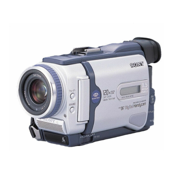
Photo : DCR-TRV30E
RMT-811
SPECIFICATIONS
Recording/playback time (using
cassette DVM60)
SP: 1 hour
LP: 1.5 hours
Fastforward/rewind time
(using cassette DVM60)
Approx. 2 min. and 30 seconds
Viewfinder
Electric viewfinder (colour)
Image device
4.5 mm (1/4 type) CCD (Charge
Coupled Device)
Approx. 1 550 000 pixels
(Effective (moving): 970 000 pixels)
(Effective (still): 1 390 000 pixels)
Lens
Carl Zeiss
Combined power zoom lens
Filter diameter: 37 mm
(1 1/2 in)
10× (Optical), 120× (Digital)
DIGITAL VIDEO CAMERA RECORDER
Hong Kong Model
For MECHANISM ADJUSTMENTS, refer to the
"DV MECHANICAL ADJUSTMENT MANUAL
J MECHANISM " (9-929-807-11).
DCR-TRV30
: NTSC model
DCR-TRV30E : PAL model
Focal length
4.2 – 42 mm (3/16 – 1 11/16 in.)
When converted to a 35 mm still
camera
Camera mode:
48 – 480 mm (1 15/16 – 19 in.)
Memory mode:
40 – 400 mm (1 5/8 – 15 3/4 in.)
Colour temperature
Auto, HOLD (Hold),
Indoor
(3 200 K),
Outdoor (5 800 K)
Minimum illumination
7 lx (lux) (F 1.8)
0 lx (lux) (in the NightShot
mode)*
* Objects unable to be seen due
to the dark can be shot with
infrared lighting.
RMT-811
US Model
Canadian Model
Korea Model
DCR-TRV30
AEP Model
UK Model
Australian Model
Chinese Model
DCR-TRV30E
E Model
Tourist Model
DCR-TRV30/TRV30E
J MECHANISM
Input/Output connectors
S video input/output
4-pin mini DIN
Luminance signal: 1 Vp-p,
75 Ω (ohms), unbalanced
Chrominance signal:
DCR-TRV30: 0.286 Vp-p,
DCR-TRV30E: 0.3 Vp-p,
75 Ω (ohms), unbalanced
Audio/Video input/output
AV MINI JACK, 1 Vp-p,
75 Ω (ohms), unbalanced, sync
negative
327 mV, (at output impedance
more than 47 kΩ (kilohms)
Output impedance with less than
2.2 kΩ (kilohms)/Stereo minijack
(ø 3.5mm)
Input impedance more than
47 kΩ (kilohms)
— Continued on next page —
Advertisement
Table of Contents

Related Manuals for Sony DCR-TRV30E


Summary of Contents for Sony DCR-TRV30E
- Page 1 DCR-TRV30 : NTSC model Therefore, schematic diagram, printed wiring board, waveforms, parts DCR-TRV30E : PAL model location and electrical parts list of the VC-264 board are not shown. The following pages are not shown. Printed wiring board ......Pages 4-51 to 4-54 Schematic diagram ......
-
Page 2: Battery Pack
MARK 0 ON THE SCHEMATIC DIAGRAMS AND IN THE PARTS CRITIQUES POUR LA SÉCURITÉ DE FONCTIONNEMENT. NE LIST ARE CRITICAL TO SAFE OPERATION. REPLACE THESE REMPLACER CES COMPOSANTS QUE PAR DES PIÈSES SONY COMPONENTS WITH SONY PARTS WHOSE PART NUMBERS DONT LES NUMÉROS SONT DONNÉS DANS CE MANUEL OU APPEAR AS SHOWN IN THIS MANUAL OR IN SUPPLEMENTS DANS LES SUPPÉMENTS PUBLIÉS PAR SONY. - Page 3 Lens hood (1) 3 Size AA (R6) battery for Remote qs 21-pin adaptor (1) Commander (2) DCR-TRV30E: AEP, UK only 4 NP-FM50 battery pack (1) qd 2-pin conversion adaptor (1) 5 A/V connecting cable (1) DCR-TRV30: JE/TRV30E: JE only...
-
Page 4: Table Of Contents
TABLE OF CONTENTS SERVICE NOTE Recording video or TV programmes ··································· 1-25 Inserting a scene from a VCR – Insert editing ····················· 1-26 POWER SUPPLY DURING REPAIRS ····························· 7 Audio dubbing ····································································· 1-27 TO TAKE OUT A CASSETTE WHEN NOT EJECT Superimposing a title ···························································... - Page 5 PRINTED WIRING BOARDS AND 5-1. CAMERA SECTION ADJUSTMENT ··························· 5-4 1-1. PREPARATIONS BEFORE ADJUSTMENT SCHEMATIC DIAGRAMS (CAMERA SECTION) ··················································· 5-4 4-1. FRAME SCHEMATIC DIAGRAM (1/2) ······················· 4-1 1-1-1. List of Service Tools ························································ 5-4 FRAME SCHEMATIC DIAGRAM (2/3) ······················· 4-3 1-1-2.
- Page 6 REPAIR PARTS LIST 5-2. MECHANISM SECTION ADJUSTMENT ·················· 5-39 2-1. HOW TO ENTER RECORD MODE WITHOUT 6-1. EXPLODED VIEWS ······················································ 6-1 CASSETTE ··································································· 5-39 6-1-1. OVERALL SECTION ····················································· 6-1 2-2. HOW TO ENTER PLAYBACK MODE WITHOUT 6-1-2. CABINET (R) SECTION ··············································· 6-2 CASSETTE ···································································...
-
Page 7: Service Note
SERVICE NOTE POWER SUPPLY DURING REPAIRS In this unit, about 10 seconds after power is supplied to the battery terminal using the regulated power supply (8.4V), the power is shut off so that the unit cannot operate. This following two methods are available to prevent this. Take note of which to use during repairs. Method 1. -
Page 8: Discharging Of The Flashlight Power
DISCHARGING OF THE FLASHLIGHT POWER SUPPLY CAPACITOR The power supply capacitor of the flash unit is charged up to the maximum 300V potential. There is a danger of electric shock by this high voltage when the capacitor is handled by hand. The electric shock is caused by the charged voltage which is kept without discharging when the main power of the unit is simply turned off. -
Page 9: Self-Diagnosis Function
SELF-DIAGNOSIS FUNCTION SELF-DIAGNOSIS FUNCTION SELF-DIAGNOSIS DISPLAY When problems occur while the unit is operating, the self-diagnosis When problems occur while the unit is operating, the counter of the function starts working, and displays on the viewfinder, LCD screen viewfinder, LCD screen or LCD window consists of an alphabet or LCD window what to do. -
Page 10: Self-Diagnosis Code Table
SELF-DIAGNOSIS CODE TABLE Self-diagnosis Code Block Detailed Symptom/State Correction Function Code Non-standard battery is used. Use the info LITHIUM battery. Condensation. Remove the cassette, and insert it again after one hour. Video head is dirty. Clean with the optional cleaning cassette. LOAD direction. -
Page 11: General
DCR-TRV30/TRV30E SECTION 1 This section is extracted from instruction GENERAL manual. (DCR-TRV30E)(3-067-862-11) English Main Features Taking moving or still images, and playing them back •Recording a picture (p. 26) •Recording a still image on a tape (p. 48) •Playing back a tape (p. 39) •Recording still images on “Memory Stick”s (p. -
Page 12: Getting Started
— Getting started — Using this manual Using this manual Precautions on camcorder care As you read through this manual, buttons and Lens and LCD screen/finder (on settings on your camcorder are shown in capital mounted models only) letters. •The LCD screen and the finder are e.g. -
Page 13: Charging The Battery Pack
“InfoLITHIUM” battery. “InfoLITHIUM” M series battery packs have the mark. Notes SERIES “InfoLITHIUM” is a trademark of Sony •The AC power adaptor can supply power even Corporation. if the battery pack is attached to your We recommend charging the battery pack in an camcorder. -
Page 14: Step 2 Setting The Date And Time
Step 2 Setting the Step 2 Resetting the date and date and time time The year changes as follows: Set the date and time settings when you use your camcorder for the first time. “CLOCK SET” will 1995 T · · · · t 2001 T · · · · t 2079 be displayed each time that you set the POWER switch to CAMERA/MEMORY unless you set the date and time settings. -
Page 15: Recording - Basics
— Recording – Basics — Recording a picture Recording a picture Your camcorder automatically focuses for you. Note on Recording mode Your camcorder records and plays back in the SP (1) Remove the lens cap by pressing both knobs (standard play) mode and in the LP (long play) on its sides and attach the lens cap to the grip mode. -
Page 16: Shooting Backlit Subjects - Back Light
Recording a picture Recording a picture Viewfinder backlight Adjusting the viewfinder You can change the brightness of the backlight. Select VF B.L. in the menu settings only when If you record pictures with the LCD panel closed, using the battery pack. check the picture with the viewfinder. -
Page 17: Shooting In The Dark - Nightshot/Super Nightshot
Recording a picture Recording a picture Shooting in the dark Notes •Do not use the NightShot function in bright – NightShot/Super NightShot places (ex. the outdoors in the daytime). This may cause your camcorder to malfunction. The NightShot function enables you to shoot a •When you keep NIGHTSHOT set to ON in subject in a dark place. -
Page 18: Playback - Basics
— Playback – Basics — Checking the recording Playing back a tape – END SEARCH / EDITSEARCH / Rec Review You can monitor the playback picture on the screen. If you close the LCD panel, you can Rec Review monitor the playback picture in the viewfinder. You can control playback using the Remote You can check the last recorded section. -
Page 19: Viewing The Recording On Tv
Playing back a tape Playing back a tape To view the picture frame-by-frame Various playback modes Press C on the Remote Commander in the playback pause mode. For frame-by-frame To operate video control buttons, set the POWER playback in the reverse direction, press c. To switch to VCR. -
Page 20: Advanced Recording Operations
The super laser link function turns off receiver automatically. Once you connect the AV cordless IR receiver If you use a Sony TV (Except for European (optional) to your TV or VCR, you can easily models) view the picture on your TV. For details, refer to •You can turn on the TV automatically when... - Page 21 Recording a still image on a tape Recording a still image on a tape – Tape Photo recording – Tape Photo recording You cannot shoot images with the flash The flash is adjusted to the appropriate brightness through the photocell window for the during the following operations: flash.
-
Page 22: Adjusting The White Balance Manually
Adjusting the white Adjusting the white balance balance manually manually In the automatic white balance mode You can manually adjust and set the white balance. This adjustment makes white subjects Point your camcorder at a white subject for about look white and allows more natural colour 10 seconds after setting the POWER switch to balance. -
Page 23: Using The Fader Function
Using the fader function Using the fader function You can fade in or out to give your recording a (1) When fading in [a] professional appearance. In the standby mode, press FADER until the desired fader indicator flashes. When fading out [b] In the recording mode, press FADER until the STBY desired fader indicator flashes. -
Page 24: Using Special Effects - Digital Effect
Using special effects Using special effects – Digital effect – Digital effect (1) In CAMERA mode, press DIGITAL EFFECT. The digital effect indicator appears. You can add special effects to recorded pictures (2) Turn the SEL/PUSH EXEC dial to select the using the various digital functions. -
Page 25: Adjusting The Exposure Manually
Using the PROGRAM AE function Using the PROGRAM AE function (1) In CAMERA or MEMORY mode, press •While shooting in MEMORY mode the PROGRAM AE. The PROGRAM AE indicator following modes do not work (The indicator appears. flashes.): (2) Turn the SEL/PUSH EXEC dial to select the –... -
Page 26: Interval Recording
Interval recording Focusing manually You can make a time-lapse recording by setting To focus precisely the camcorder to automatically record and It is easier to focus on the subject if you adjust the standby sequentially. You can achieve an zoom to shoot at the “W” (wide-angle) after excellent recording for flowering, emergence, focusing at the “T”... -
Page 27: Frame By Frame Recording - Cut Recording
Frame by frame recording Frame by frame recording – Cut recording – Cut recording To cancel the cut recording You can make a recording with a stop-motion animated effect using cut recording. To create •Set FRAME REC to OFF in the menu settings. this effect, alternately move the subject a little •Set the POWER switch to OFF (CHG), VCR, or and make a cut recording. -
Page 28: Playing Back A Tape With Digital Effects
Enlarging images Playing back a tape with digital recorded on tapes effects – Tape PB ZOOM Pictures processed by the digital effect function You can enlarge playback images recorded on •Pictures processed by the digital effect function tapes. You can also dub the enlarged images to are not output through the DV IN/OUT jack. -
Page 29: Searching The Boundaries Of Recorded Tape By Title
Searching the boundaries of Searching the boundaries recorded tape by title of recorded tape by title – Title search – Title search If a tape has a blank portion between recorded portions If you use a tape with cassette memory, The title search function may not work correctly. -
Page 30: Searching For A Photo - Photo Search/Photo Scan
Searching for a photo Searching for a photo – Photo search/Photo scan – Photo search/Photo scan You can search for a still image you have In the mark recorded on a tape (photo search). •The bar in the mark indicates the You can also search for still images one after present point on the tape. -
Page 31: Dubbing Only Desired Scenes - Digital Program Editing
Dubbing a tape Dubbing a tape Using the i.LINK cable (DV connecting You can edit on VCRs that support the cable) following systems Simply connect the i.LINK cable (DV connecting 8 mm, Hi8, VHS, S-VHS, cable) (optional) to DV IN/OUT and to DV IN VHSC, S-VHSC, Betamax,... - Page 32 VCR. The default setting is CAMERA Code number 3. MEMORY MENU IR SETUP code/ IR SETUP code/ Brand/ Brand/ Sony 1, 2, 3, 4, 5, 6 Nokia 89, 36 Aiwa 47, 53, 54 Nokia Oceanic Akai 62, 50, 74...
- Page 33 Dubbing only desired scenes Dubbing only desired scenes – Digital program editing – Digital program editing (2) Setting the modes to cancel the (4) Confirming the VCR operation recording pause on the VCR 1 Insert a recordable tape into the VCR, then set to recording pause.
- Page 34 Dubbing only desired scenes Dubbing only desired scenes – Digital program editing – Digital program editing Operation 1: Making the programme (1) Insert the tape for playback into your camcorder, and insert a tape for recording into the VCR. (2) Press MENU to display the menu. (3) Turn the SEL/PUSH EXEC dial to select then press the dial.
-
Page 35: Using With Analog Video Unit And Personal Computer
Using with analog video Dubbing only desired scenes unit and personal computer – Digital program editing – Signal convert function You cannot record on the VCR when: – The tape has run out. You can capture images and sound from an –... -
Page 36: Inserting A Scene From A Vcr - Insert Editing
Set DISPLAY to LCD in the menu settings. (The VCRs to avoid remote control misoperation. If default setting is LCD.) you use another Sony VCR in the commander mode VTR 2, we recommend changing the (1) Insert a blank tape (or a tape you want to... -
Page 37: Audio Dubbing
VTR 2. Commander modes 1, 2 and 3 are used to distinguish your camcorder from other Sony VCRs to avoid remote control misoperation. If you use another Sony VCR in the commander mode VTR 2, we recommend changing the commander mode or covering the sensor of the VCR with black paper. -
Page 38: Superimposing A Title
We recommend that you add new sound on a tape recorded with your camcorder If you add new sound on a tape recorded with another camcorder (including other DCR-TRV30E), the sound quality may become AUDIO DUB worse. If you set the write-protect tab of the tape to lock You cannot record on a tape. -
Page 39: Making Your Own Titles
Superimposing a title Superimposing a title Title setting •The title colour changes as follows: WHITE y YELLOW y VIOLET y RED y P R E S E T T I T L E P R E S E T T I T L E H E L L O ! H E L L O ! CYAN y GREEN y BLUE... -
Page 40: Labelling A Cassette
Labelling a cassette Making your own titles To change a title you have stored If you use a tape with cassette memory, you can label a cassette. The label can In step 3, select CUSTOM1 SET or CUSTOM2 SET, depending on which title you want to consist of up to 10 characters and is stored in cassette memory. - Page 41 Changing the menu settings Changing the menu settings To make the menu display disappear POWER Icon/item Mode Meaning switch Press MENU. FRAME REC z OFF CAMERA To deactivate Cut recording function. Menu items are displayed as the following To activate Cut recording function. (p. 74) icons: INT.
-
Page 42: Memory Stick" Operations
When you play back the tape on other camcorders or VCRs, noise may occur in pictures or sound. •When you record in the LP mode, we recommend using a Sony Excellence/Master cassette so that you can get the most out of your camcorder. - Page 43 Do not shake or strike your camcorder because •“Memory Stick” and are trademarks of your camcorder is reading the data from the Sony Corporation. “Memory Stick” or recording the data on the •Windows and ActiveMovie, DirectShow are “Memory Stick.” Do not turn the power off , eject either registered trademarks or trademarks of a “Memory Stick”...
- Page 44 Using a “Memory Stick” Using a “Memory Stick” – introduction – introduction Selecting the image size MEMOR Y S E T S T I L L S E T MO V I E S E T You can select either one of two image sizes P R I N T MA R K P RO T E C T Still images: 1360 ×...
-
Page 45: Recording Still Images On "Memory Stick"S
Recording still images on Recording still images on “Memory Stick”s “Memory Stick”s – Memory Photo recording – Memory Photo recording When the POWER switch is set to MEMORY The following functions do not work: You can record still images on “Memory Stick”s. –... - Page 46 Recording still images on Recording still images on “Memory Stick”s “Memory Stick”s – Memory Photo recording – Memory Photo recording If the capacity of the “Memory Stick” Recording images with the becomes full flash ” FULL” appears on the screen, and you cannot record a still image on this “Memory The flash automatically pops up to strobe.
-
Page 47: Recording An Image From A Tape As A Still Image
Recording an image Recording an image from a tape from a tape as a still as a still image image If “ ” appears on the screen The inserted “Memory Stick” is incompatible Your camcorder can read moving picture data with your camcorder because its format does not recorded on a tape and record it as a still image conform with your camcorder. -
Page 48: Recording A Picture From A Tape As A Moving Picture
Recording moving pictures on Recording a picture “Memory Stick”s from a tape as a – MPEG movie recording moving picture Note Sound is recorded in monaural. Your camcorder can read moving picture data recorded on a tape and record it as a moving When the POWER switch is set to MEMORY picture on a “Memory Stick.”... -
Page 49: Superimposing A Still Picture In A "Memory Stick" On A Moving Picture - Memory Mix
Superimposing a still picture in Recording a picture from a tape a “Memory Stick” on a moving as a moving picture picture – MEMORY MIX Using the i.LINK cable (DV connecting cable) You can superimpose a still image you have recorded on a “Memory Stick”... -
Page 50: Copying Still Images From A Tape - Photo Save
Superimposing a still picture in a “Memory Stick” on a moving Copying still images picture – MEMORY MIX from a tape – Photo save To change the still image to be superimposed Using the search function, you can automatically Do either of the following: take in only still images from tapes and record –... -
Page 51: Viewing A Moving Picture - Mpeg Movie Playback
Viewing a still picture Viewing a still picture – Memory photo playback – Memory photo playback Notes on the file name Playing back 6 recorded images •The directory is not displayed if the structure of at a time (index screen) the directory does not conform to the DCF98 standard. -
Page 52: Viewing Images Using Your Computer
(2) Insert the supplied CD-ROM in the CD-ROM the window opened in step 4 (drag and drop). drive of your computer. •Sony Camcorder USB Driver (3) Launch the application programme on CD- •Sony Camcorder USB Shim ROM. After a moment, the dialog box appears (6) When “Put these items into the Extensions... -
Page 53: Copying The Image Recorded On "Memory Stick"S To Tapes
Viewing images using your Viewing images using your computer computer Viewing images Unplug the USB cable/Eject the “Memory Stick” For Windows 98 users (1) Turn on the power of your computer and To unplug the USB cable or eject the “Memory allow Windows 98 to load. -
Page 54: Enlarging Still Images Recorded On "Memory Stick"S
Enlarging still images Copying the image recorded on recorded on “Memory “Memory Stick”s to tapes Stick”s – Memory PB ZOOM During copying You cannot operate the following buttons: You can enlarge still images recorded on a – MEMORY PLAY “Memory Stick.” You can select and view the –... -
Page 55: Preventing Accidental Erasure - Image Protection
Preventing accidental Playing back images in a erasure continuous loop – SLIDE SHOW – Image protection To start the slide show from a particular image To prevent accidental erasure of important Select the desired image using MEMORY +/– images, you can protect selected images. buttons before step 2. -
Page 56: Writing A Print Mark - Print Mark
Deleting images Deleting images To cancel deleting all the images in Deleting all the images the “Memory Stick” Select RETURN in step 5, then press the SEL/ You can delete all the unprotected images in a PUSH EXEC dial. “Memory Stick.” Before operation While DELETING appears Insert a “Memory Stick”... -
Page 57: Using The Printer (Optional)
Set it to OFF. (p. 34) unnatural colours. problem. If the problem persists, disconnect the power source and contact your Sony dealer or local authorised Sony service facility. If “C:ss:ss” appears on the screen, the self-diagnosis The picture appears too bright, and •... - Page 58 (p. 25) • Something is wrong with the battery pack. c Contact your Sony dealer or local authorised Sony • The tape has a blank portion in the recorded portion. c Superimpose the title to the recorded position. (p. 122) service facility.
-
Page 59: Self-Diagnosis Display
• A malfunction that you cannot service has occurred. compartment open (p. 229). • The self-diagnosis display function is c Contact your Sony dealer or local authorised Sony E:62:ss activated (p. 209). service facility and inform them of the 5-digit code. -
Page 60: About The "Infolithium" Battery Pack
Usable cassettes Usable cassettes Copyright signal When you play back a dual sound track tape When you play back Using any other video camera recorder, you When you play back a dual sound track tape cannot record on tape that has recorded a recorded in a stereo system, set HiFi SOUND to copyright control signals for copyright protection the desired mode in the menu settings (p. -
Page 61: About I.link
IEEE 1394 data supported by this unit is already installed on the transport bus proposed by SONY, and is a personal computer. trademark approved by many corporations. - Page 62 [a] [b] or 8.4 V (AC power adaptor). If the above problem, [a], [b] or [c] occurs, clean the video heads for 10 seconds with the Sony •For DC or AC operation, use the accessories recommended in this operating instructions.
-
Page 63: Quick Reference
The lens for your camcorder was developed jointly by Carl Zeiss, in Germany, and Sony Corporation. It adopts the MTF* measurement system for video camera and offers a quality as the Carl Zeiss lens. - Page 64 Identifying the parts and controls Identifying the parts and controls MEMORY MPEG PLAY INDEX DELETE MEMORY MIX PLAY SELFTIMER button (p. 36, 52, 160) STOP PAUSE rh OPEN button (p. 26) rj VOLUME buttons (p. 39) rk RESET button eh DISPLAY button (p. 40) rl MEMORY operation buttons ej DATA CODE button (p.
- Page 65 VTR 2. Commander modes 1, 2 and 3 are used to distinguish your camcorder from other Sony VCRs to avoid remote control misoperation. If you use another Sony VCR in the commander mode VTR 2, we recommend changing the 1 Cassette memory indicator (p. 32, 221)
-
Page 66: Disassembly
DCR-TRV30/TRV30E SECTION 2 DISASSEMBLY The following flow chart shows the disassembly procedure. 2-1. LCD section (PD-145 board) PD-145 board service position 2-2. EVF section (LB-072 board) LB-072 board service position MI-043, ML-023 boards service position 2-3. Front panel section (MI-043, ML-023, SE-121 boards) CK-102, MI-043, ML-023 boards service position 2-4. -
Page 67: Lcd Section (Pd-145 Board)
NOTE: Follow the disassembly procedure in the numerical order given. 2-1. LCD SECTION (PD-145 BOARD) Two screws (M1.7 × 4), Two screws (M1.7 × 2.5), p lock ace, p2 Five claws P cabinet (C) assembly Two screws (M1.7 × 4), lock ace, p2 PD-145 board, Inverter transformer unit,... -
Page 68: Evf Section (Lb-072 Board)
2-2. EVF SECTION (LB-072 BOARD) 1 Raise the EVF in the A direction and slide it in the B direction. 2 VF cabinet (upper) assembly 1Two claws Two tapping screws (M1.7 × 5) Three claws Two tapping screws (M1.7 × 5) 5 VF lens assembly 3 VF cabinet (lower) assembly... -
Page 69: Front Panel Section (Mi-043, Ml-023, Se-121 Boards)
2-3. FRONT PANEL SECTION (MI-043, ML-023, SE-121 BOARDS) Two screws (M1.7 × 4), lock ace, p2 Open the flash unit Screw (M1.7 × 4), lock ace, p2 FP-327 flexible board (37P) Open the jack cover assembly Screw Front panel section (M1.7 ×... -
Page 70: Cabinet (R) Section (Ck-102 Board)
2-4. CABINET (R) SECTION (CK-102 BOARD) PRECAUTION DURING INSTALLATION (ROUTING OF HARNESS) If must not go outside the upper and lower ribs. TOP cabinet assembly Three claws Screw (M1.7 × 4), lock ace, p2 Screw (M1.7 × 4), lock ace, p2 qd Cabinet (R) section Extra length inside the cabinet is as much as shown. -
Page 71: Bt Panel Section, Evf Section
2-5. BT PANEL SECTION, EVF SECTION 4 Claw 2 Two screws (M1.7 × 4), 9 Screw lock ace, p2 (M1.7 × 2.5), p 5 BT panel section q; Control switch block (FK-1800) (15P) 1 Battery terminal board (6P) qd EVF section qs Two tapping screws (M1.7 ×... -
Page 72: Lens Section (Jk-207 Board)
2-7. LENS SECTION (JK-207 BOARD) PRECAUTION DURING INSTALLATION Note on attachment When attaching the lens block, flip up the switch actuator and insert it to the up position of the NIGHT SHOT lever in the direction as shown. Two tapping screws (M1.7 ×... - Page 73 [SERVICE POSITION TO CHECK THE VTR SECTION] Connection to Check the VTR Section To check the VTR Section, set the VTR to the "forced VTR power ON" mode. Operate the VTR functions using the adjustment remote commander (with the HOLD switch set in the OFF position) Setting the “Forced VTR Power ON”...
-
Page 74: Control Switch Block (Fk-1800), Control Switch Block (Ps-1800)
2-8. CONTROL SWITCH BLOCK (FK-1800), CONTROL SWITCH BLOCK (PS-1800) Note: The power supply capacitor of the flash unit is charged to the high tension voltage as high as 300 V at a maximum. You will get electrical shock when you touch the terminal of the charged capacitor. The charged potential remains even after the main power of the machine is turned off. -
Page 75: Flash Unit
2-9. FLASH UNIT Note: The power supply capacitor of the flash unit is charged to the high tension voltage as high as 300 V at a maximum. You will get electrical shock when you touch the terminal of the charged capacitor. The charged potential remains even after the main power of the machine is turned off. -
Page 76: Grip Belt
2-11.GRIP BELT Note: The power supply capacitor of the flash unit is charged to the high tension voltage as high as 300 V at a maximum. You will get electrical shock when you touch the terminal of the charged capacitor. The charged potential remains even after the main power of the machine is turned off. -
Page 77: Circuit Boards Location
2-12.CIRCUIT BOARDS LOCATION LB-072 (EVF, BACKLIGHT) JK-207 (AV IN/OUT, STEADY SHOT) FLASH UNIT VC-264 CAMERA PROCESS, VIDEO PROCESS, AUDIO PROCESS, DV/STILL PROCESS, ML-023 SERVO, MODE/MECHA CONTROL, (LANC, EXT MIC) REC/PB AMP, DC/DC CONVERTER MI-043 (MIC AMP, IR TRANSMITTER) PD-145 INVERTER (RGB DRIVE, TG, LCD DRIVE) TRANSFORMER UNIT CD-320... -
Page 78: Flexible Boards Location
2-13.FLEXIBLE BOARDS LOCATION The flexible boards contained in the mechanism deck and that in the zoom lens are not shown. CONTROL SWITCH BLOCK CONTROL SWITCH BLOCK (PS-1800) (FK-1800) FP-181 FP-327 FP-329 FP-182 CONTROL SWITCH BLOCK (KP-1800) FP-325 CONTROL SWITCH BLOCK (VB-1800) PLUNGER SOLENOID FP-330... -
Page 79: Block Diagrams
DCR-TRV30/TRV30E SECTION 3 BLOCK DIAGRAMS 3-1. OVERALL BLOCK DIAGRAM (1/4) ( ) : Page No. shown in ( ) indicates the page to refer on the schematic diagram. CD-320 BOARD VC-264 BOARD(1/4) J3004 LENS ASSY DATA TO SFD2 (4-11) IC361 DV IN/OUT (4-15) DATA FROM SFD2... -
Page 80: Overall Block Diagram (2/4)
DCR-TRV30/TRV30E 3-2. OVERALL BLOCK DIAGRAM (2/4) ( ) : Page No. shown in ( ) indicates the page to refer on the schematic diagram. CN009 J MECHA DECK FOR ADJUSTMENTS (SEE PAGE 4-56) (4-32) VC-264 BOARD(2/4) RF MON IC602 REC CK REC CK CN601 REC DT... -
Page 81: Overall Block Diagram (3/4)
DCR-TRV30/TRV30E 3-3. OVERALL BLOCK DIAGRAM (3/4) ( ) : Page No. shown in ( ) indicates the page to refer on the schematic diagram. FP-181 CK-102 BOARD(1/2) VC-264 BOARD(3/4) (FLEXIBLE) (SEE PAGE 4-65) (SEE PAGE 4-64) (4-37) CN003 IC1104 35 35 CN96 S3202-3224 KEY AD2... -
Page 82: Overall Block Diagram (4/4)
DCR-TRV30/TRV30E 3-4. OVERALL BLOCK DIAGRAM (4/4) ( ) : Page No. shown in ( ) indicates the page to refer on the schematic diagram. CN009 FOR ADJUSTMENTS VC-264 BOARD(4/4) CK-102 BOARD PD-145 BOARD(2/2) (2/2) (4-85) LCD902 IC2171 COM1-4 CN003 CN3201 CN3202 CN2179 SEG1-16... -
Page 83: Power Block Diagram (1/2)
DCR-TRV30/TRV30E 3-5. POWER BLOCK DIAGRAM (1/2) ( ) : Page No. shown in ( ) indicates the page to refer on the schematic diagram. VC-264 BOARD(1/2) SHOE UNREG CS DD PRT UNREG BT901 Q1607,1626,1627, OSD SO 1636-1638 XOSD SCK BATTERY TERMINAL CN1601 SYS RST... -
Page 84: Power Block Diagram (2/2)
DCR-TRV30/TRV30E 3-6. POWER BLOCK DIAGRAM (2/2) ( ) : Page No. shown in ( ) indicates the page to refer on the schematic diagram. CN001 CN011 VC-264 BOARD(2/2) MS VCC MEMORY STICK CS DD OSD SO SHOE UNREG XOSD SVK IC1104 (4-37) INTELLIGENT... -
Page 85: Printed Wiring Boards And Schematic Diagrams
DCR-TRV30/TRV30E SECTION 4 PRINTED WIRING BOARDS AND SCHEMATIC DIAGRAMS 4-1. FRAME SCHEMATIC DIAGRAM (1/3) CD-320 BOARD LENS UNIT IMAGER CN201 FLASH UNIT CN251 ND_DRIVE+ ND DRIVE- ND HALL+ ND BIAS+ ND HALL- ND BIAS- FP-330 Z_MR_A Z_MR_GND FLEXIBLE Z_MR_B Z_MR_VCC IRIS_HALL+ IRIS_HALL- IRIS_BIAS-... -
Page 86: Frame Schematic Diagram (1/2)
DCR-TRV30/TRV30E FRAME SCHEMATIC DIAGRAM (2/3) CN103 CN2002 ML-023 BOARD MI-043 BOARD J101 EXT_IN_L EXT_IN_L LANC AU_GND AU_GND 1/2 MIC AMP EXT_IN_R EXT_IN_R CN2001 2/2 IR TRANSMITTER AU_GND AU_GND INT MIC L L-CH D101 MIC901 KEY_AD1M KEY_AD1M INT MIC GND (TALLY) MIC UNIT J102 REG_GND... -
Page 87: Frame Schematic Diagram (2/3)
DCR-TRV30/TRV30E FRAME SCHEMATIC DIAGRAM (3/3) LCD902 CHARACTER DISPLAY FP-182 FLEXIBLE CN2101 CK-102 BOARD 1/2 CONTROL SWITCH 2/2 LCD DRIVE CN3201 CN3203 170P CN2173 HCNT/LCNT XSYS_RST KEY_AD7 KEY_AD7 MCLK EVF_R EVF_G PANEL_COM PANEL_COM PC-119 EVF_B P_UNREG_GND P_UNREG_GND LCD901 HARNESS DISP_HD DISP_VD P_UNREG_GND P_UNREG_GND 3.5 INCH... -
Page 88: Printed Wiring Board
DCR-TRV30/TRV30E 4-2. PRINTED WIRING BOARDS AND SCHEMATIC DIAGRAMS THIS NOTE IS COMMON FOR WIRING BOARDS AND SCHEMATIC DIAGRAMS (In addition to this, the necessary note is printed in each block) (For printed wiring boards) (Measuring conditions voltage and waveform) • b: Pattern from the side which enables seeing. •... - Page 89 DCR-TRV30/TRV30E CD-320 (CCD IMAGER) PRINTED WIRING BOARD • : Uses unleaded solder. — Ref. No. CD-320 Board; 20,000 Series — For printed wiring board • Refer to page 4-93 for parts location. • This board consists of multiple layers. However, only CD-320 (CCD IMAGER) the sides (layers) A and B are shown.
- Page 90 DCR-TRV30/TRV30E For Schematic Diagram • Refer to page 4-9 for printed wiring board. • Refer to page 4-87 for waveform. CD-320 BOARD CCD IMAGER -REF.NO.:20000 SERIES- XX MARK:NO MOUNT C216 1500P (TRV30) L201 NO MARK:REC/PB MODE C214 4.7u C216 100uH 2200P (TRV30E) TA B...
- Page 91 Schematic diagram and printed wiring board of the VC-264 board are not shown. Pages from 4-13 to 4-54 are not shown.
-
Page 92: Mode Switch), Fp-228 (Dew Sensor), Fp-102 (Tape Top/End Sensor, S/T Reel) Flexible Boards
DCR-TRV30/TRV30E FP-100 (MODE SWITCH), FP-228 (DEW SENSOR), FP-102 (TAPE TOP/END SENSOR, S/T REEL) FLEXIBLE BOARDS — Ref. No. FP-100, 102, 228 Flexible Board; 50,000 Series — Q902 TAPE TOP SENSOR FP-102 FLEXIBLE BOARD 1-677-085- D901 S903 (CC DOWN) (TAPE LED) S901 (REC PROOF) CN901... - Page 93 DCR-TRV30/TRV30E FK-1800 (CONTROL SWITCH BLOCK) PRINTED WIRING BOARD CONTROL SWITCH BLOCK CONTROL SWITCH BLOCK (FK-1800) (FK-1800) RV061 S061 ZOOM CN008 EJECT LND082 D_2.8V REG GND LND081 S071 ZOOM_AD REG GND PHOTO R086 (PHOTO FREEZE) CONTROL SWITCH BLOCK XPHOTO_FREEZE (PS-1800) CN001 XEJECT_SW XPHOTO_STBY_SW PHOTO...
-
Page 94: Control Switch, Lcd Drive
DCR-TRV30/TRV30E CK-102 (CONTROL SWITCH, LCD DRIVE) PRINTED WIRING BOARD • : Uses unleaded solder. — Ref. No. CK-102 Board; 30,000 Series — For printed wiring board • Refer to page 4-93 for parts location. • This board consists of multiple layers. However, only CD-320 (CCD IMAGER) the sides (layers) A and B are shown. - Page 95 DCR-TRV30/TRV30E • : Uses unleaded solder. CONTROL SWITCH, LCD DRIVE 4-61 4-62 CK-102...
-
Page 96: Control Switch
DCR-TRV30/TRV30E For Schematic Diagram • Refer to page 4-59 for printed wiring board of CK-102 board. • Refer to page 4-68 for printed wiring board of PO-006 board and FP-181 flexible. CN3202 R3227 OSD_SO OSD_SO CK-102 BOARD(1/2) R3228 XOSD_SCK XOSD_SCK XCS_LCD_DRIVER CONTROL SWITCH XCS_LCD_DRIVER... -
Page 97: Lcd Drive
DCR-TRV30/TRV30E For Schematic Diagram • Refer to page 4-59 for printed wiring board of CK-102 board. • Refer to page 4-67 for printed wiring board of LB-072 board. • Refer to page 4-87 for waveforms. CK-102 BOARD(2/2) LCD DRIVE SIGNAL PATH L1803 C1812 C1814... -
Page 98: Evf Back Light), Po-006 (Panel Open/Close), Fp-181 (Panel Reverse) Printed Wiring Boards
DCR-TRV30/TRV30E LB-072 (EVF, BACK LIGHT), PO-006 (PANEL OPEN/CLOSE), FP-181 (PANEL REVERSE) PRINTED WIRING BOARDS — Ref. No. LB-072 Board; 30,000 Series — • : Uses unleaded solder. • : Uses unleaded solder. • Refer to page 4-64 for schematic diagram. PANEL For printed wiring board •... -
Page 99: Mic Amp, Ir Transmitter
DCR-TRV30/TRV30E MI-043 (MIC AMP, IR TRANSMITTER) PRINTED WIRING BOARD • : Uses unleaded solder. — Ref. No. MI-043 Board; 30,000 Series — For printed wiring board • Refer to page 4-93 for parts location. • This board consists of multiple layers. However, only VC-264 CAMERA PROCESS, VIDEO PROCESS, the sides (layers) A and B are shown. - Page 100 MF_LED MF_LED MF_LED IR_CARR CONNECTOR MF_A -REF.NO.:20000 SERIES- IR_V_DEV MF_A MF_A IR_A_DEV REG_GND FP-329 MF_B R104 IR_VIDEO D101 MF_B MF_B TLSU1002(TPX1,SONY) AU_2.8V AU_2.8V A_2.8V (TALLY) LANC_DC FLEXIBLE LANC_DC LANC_DC IR_L TO(2/2) FB103 0uH LANC_SIG LANC_SIG LANC_SIG IR_R J101 LANC_JACK_IN SIRCS_PWM...
- Page 101 DCR-TRV30/TRV30E For Schematic Diagram • Refer to page 4-69 for printed wiring board. • Refer to page 4-87 for waveforms. MI-043 BOARD(2/2) NO MARK:IR ON/IR OFF MODE IR TRANSMITTER ( ):IR ON MODE [ ]:IR OFF MODE -REF.NO.:30000 SERIES- XX MARK:NO MOUNT L1904 22uH A_4.6V...
- Page 102 DCR-TRV30/TRV30E JK-207 (AV IN/OUT, STEADY SHOT) PRINTED WIRING BOARD • : Uses unleaded solder. — Ref. No. JK-207 Board; 20,000 Series — (FLASH) AV IN/OUT (HEADPHONES) For printed wiring board • Refer to page 4-94 for parts location. • This board consists of multiple layers. However, only the sides (layers) A and B are shown.
- Page 103 DCR-TRV30/TRV30E For Schematic Diagram • Refer to page 4-75 for printed wiring board. R3002 JK-207 BOARD R3003 AV IN/OUT,STEADY SHOT -REF.NO.:20000 SERIES- VDR006 VDR005 VDR008 XX MARK:NO MOUNT J3001 1000p S VIDEO NO MARK:REC/PB MODE D3002 FLASH TLAU108(T05,SOY) R3007 Q3001 UN9211J-(K8).SO LED DRIVE S3001...
-
Page 104: Mf Sensor
DCR-TRV30/TRV30E ML-023 (LANC, EXT MIC), SE-121 (MF SENSOR) PRINTED WIRING BOARDS • : Uses unleaded solder. — Ref. No. ML-023, SE-121 Boards; 20,000 Series — FADER (PLUG IN POWER) BACK LIGHT For printed wiring board • Refer to page 4-94 for parts location. •... -
Page 105: Vb-1800 (Control Switch Block), Pd-145 (Rgb Drive, Tg, Lcd Drive) Printed Wiring Boards
DCR-TRV30/TRV30E VB-1800 (CONTROL SWITCH BLOCK), PD-145 (RGB DRIVE, TG, LCD DRIVE) PRINTED WIRING BOARDS • : Uses unleaded solder. — Ref. No. PD-145 Board; 30,000 Series — • Refer to page 4-86 for schematic diagram. CONTROL SWITCH BLOCK • : Uses unleaded solder. (VB-1800) S100 LCD BRIGHT -... -
Page 106: Rgb Drive, Tg
DCR-TRV30/TRV30E For Schematic Diagram • Refer to page 4-82 for printed wiring board. • Refer to page 4-88 for waveforms. PD-145 BOARD(1/2) L2106 10uH RGB DRIVE/TG L2103 10uH L2104 -REF.NO.:30000 SERIES- 10uH C2111 C2112 C2115 XX MARK:NO MOUNT C2116 3.3u 0.1u 0.1u R2158... -
Page 107: Lcd Drive
DCR-TRV30/TRV30E For Schematic Diagram • Refer to page 4-82 for printed wiring board of PD-145 board. • Refer to page 4-81 for printed wiring board of control switch block (VB-1800). • Refer to page 4-88 for waveform. PD-145 BOARD(2/2) FP-182 LCD DRIVE FLEXIBLE -REF.NO.:30000 SERIES-... -
Page 108: Waveforms
DCR-TRV30/TRV30E 4-3. WAVEFORMS CD-320 CK-102 MI-043 PD-145 BOARD BOARD BOARD BOARD Waveforms and parts location of the VC-264 board CAMERA REC REC/PB REC/PB are not shown. IC1901 7 Pages from 4-89 to 4-92 are not shown. IC202 1 IC1802 w; IC1803 wh IC2104 w;... -
Page 109: Mounted Parts Location
DCR-TRV30/TRV30E no mark : side A 4-4. MOUNTED PARTS LOCATION * mark : side B CD-320 BOARD CK-102 BOARD LB-072 BOARD MI-043 BOARD * C201 * BT3201 C-9 * R1832 C-10 C2202 * C1901 * IC1901 B-5 * C202 * R1833 C-10 C2203 * C1902 IC2002 B-2... - Page 110 DCR-TRV30/TRV30E no mark : side A * mark : side B JK-207 BOARD ML-023 BOARD SE-121 BOARD PD-145 BOARD C3051 Q3001 D-2 * C101 PH081 B-2 C2101 Q2107 C-3 C3052 C102 PH082 B-2 C2102 Q2108 C-1 C3053 R3002 A-1 * C103 C2103 Q2114 B-2 C3054...
-
Page 111: Adjustments
DCR-TRV30/TRV30E SECTION 5 ADJUSTMENTS... -
Page 112: Adjusting Items When Replacing Main Parts And Boards
1-1. Adjusting items when replacing main parts and boards. When replacing main parts, adjust the items indicated by z in the following table. Note1: When replacing the drum assy. or mechanism deck, reset the data of page: 2, address: A2 to A4 to “00”. (Refer to “Record of Use check” of “5-4. SERVICE MODE”) Replaced parts Block replacement... - Page 113 Note2: When the repair is finished, confirm the EEPROM Board replacement following items. replacement Shoot the all black subject (Attach the lens cap and shoot), and confirm that a vertical line is not displayed in the center of the screen, and that there is no difference in left-right brightness level of the screen.
-
Page 114: Camera Section Adjustment
5-1. CAMERA SECTION ADJUSTMENT 1-1. PREPARATIONS BEFORE ADJUSTMENT (CAMERA SECTION) 1-1-1. List of Service Tools • Oscilloscope • Color monitor • Vectorscope • Regulated power supply • Digital voltmeter Ref. No. Name Parts Code Usage Auto white balance adjustment/check Filter for color temperature correction (C14) J-6080-058-A White balance adjustment/check ND filter 1.0... -
Page 115: Preparations
1-1-2. Preparations Note 1: For details of how remove the cabinet and boards, refer to “2. DISASSEMBLY”. Note 2: When performing only the adjustments, the lens block and boards Pattern box need not be disassembled. Connect the equipment for adjustments according to Fig. 5-1-2. Note 3: As removing the cabinet (R) (removing the VC-264 board CN003) means removing the lithium 3V power supply (BT3201), data such 1.5 m... - Page 116 AC-power adaptor (8.4 Vdc) Adjustment remote AC-L10, commander AC-VQ800 etc. Must be connected when performing the video, EVF or LCD system adjustments. LANC jack Front panel block CN008 CN007 CN006 CN012 CN601 CN011 VC-264 board CN009 CN003 AUDIO/VIDEO jack CN1601 CN301 FP-327 MI-043 board...
-
Page 117: Precaution
1-1-3. Precaution 1. Setting the Switch Unless otherwise specified, set the switches as follows and perform adjustments without loading cassette. POWER switch (PS-1800 block) ......CAMERA 16 : 9 WIDE (Menu setting) ..........OFF NIGHT SHOT switch (Lens block) ......... OFF PICTURE EFFECT (Menu setting) ......... -
Page 118: Initialization Of B, C, D, E, F, 7, 8 Page Data
1-2. INITIALIZATION OF B, C, D, E, F, 7, 8 PAGE Processing after Completing Modification of C, D, 8 Page data: DATA Order Page Address Data Procedure Set the data. 1-2-1. INITIALIZATION OF C, D, 8 PAGE DATA Set the data, and press the PAUSE button. - Page 119 C page Address Remark Address Remark Initial value Initial value Fixed data-2 Serial No. input (Modified data. Copy the data built in the same model.) 75 to 85 Fixed data-1 Fixed data-2 (Modified data. Copy the data built in the same model.) F0 to F3 Fixed data-1 8A to 9A...
- Page 120 4. D Page Table Note: Address Initial value Remark Fixed data-1: Initialized data. NTSC (Refer to “1. Initializing the C, D, 8 Page Data”.) Fixed data-2: Modified data. Fixed data-2 (Refer to “2. Modification of C, D, 8 Page Data”). (Modified data.
- Page 121 D page 5. 8 Page Table Note: Address Initial value Remark Fixed data-1: Initialized data. NTSC (Refer to “1. Initializing the C, D, 8 Page Data”.) Fixed data-2: Modified data. Fixed data-2 (Refer to “2. Modification of C, D, 8 Page Data”). DB to DD Fixed data-1 Address...
- Page 122 1-2-2. INITIALIZATION OF B PAGE DATA Note 1: When reading the B page data, insert a “Memory Stick” into the “Memory Stick” slot. Note 2: “INITIALIZATION OF B PAGE DATA” should be carried out upon completion of “INITIALIZATION OF C, D, 8 PAGE DATA”. Switch setting: POWER ..............
-
Page 123: Initializing The C, D, 8 Page Data
Set the following data, and press CCD output 2ch matching adj. (1) PAUSE button. 2D: DCR-TRV30 (NTSC) (F No. & ND light quantity standard 2F: DCR-TRV30E (PAL) data input) Set the data. Check that the data changes to “01”. Perform “Modification of E, F, 7 Page Data”. - Page 124 F page Address Initial value Remark Address Initial value Remark NTSC NTSC MR adj. CCD output 2ch matching adj. (1) 7E to 95 Fixed data-1 Fixed data-2 97 to 99 Fixed data-1 Fixed data-2 9B to 9E Fixed data-1 Fixed data-2 A0 to A6 Fixed data-1 Fixed data-2...
-
Page 125: F Page Table
4. E Page Table Address Remark Note: Fixed data-1: Initialized data. (Refer to “1. Initializing the E, F, 7 Page Data”.) CA to DA Fixed data-1 Fixed data-2: Modified data. (Refer to “2. Modification of E, F, 7 Page Data”). Fixed data-2 Address Remark... - Page 126 7 page Address Remark Address Remark Fixed data-2 Fixed data-2 (*1) (Modified data. Copy the data built in the same model.) F9 to FC Fixed data-1 Fixed data-2 (*1) 59 to 6F Fixed data-1 Fixed data-2 Fixed data-2 (Modified data. Copy the data built in *1: Camera microprocessor version 2.0 or later only.
-
Page 127: Camera System Adjustments
Measurement Point Display data of page 1 (Note 1) Note: NTSC model: DCR-TRV30 Measuring Instrument Adjustment remote commander PAL model: DCR-TRV30E Adjustment Page 1. 40.5 MHz / 54 MHz Origin Oscillation Adjustment Adjustment Address 15, 16, 17, 18, 19, 1A... - Page 128 Set the data. Set the data. Set the following data. 21: DCR-TRV30 (NTSC) 1A: DCR-TRV30E (PAL) Set the data, and press PAUSE button. Check that the data changes to “01”. (Note 2) Note 2: The adjustment data will be automatically input to page: F, address:...
-
Page 129: Hall Adjustment
RadarW RadarW RadarW 4. CCD Output 2ch Matching Adjustment (1) 4-2. CCD Output 2ch Matching Adjustment (1) 4-1. Preparations for CCD Output 2ch Matching Adjustment Correct the dispersion of the black level between the left-right To perform the CCD output 2ch matching adjustment, correct the channels of the CCD imager. -
Page 130: Ccd Output 2Ch Matching Adjustment (1)
5. CCD Output 2ch Matching Adjustment (2) 5-2. CCD Output 2ch Matching Adjustment (2-2) RadarW RadarW RadarW RadarW RadarW 5-1. CCD Output 2ch Matching Adjustment (2-1) Correct the fine dispersion of the black level between the left-right Correct the dispersion between the left-right channels of the CCD channels of the CCD imager. - Page 131 RadarW RadarW RadarW RadarW RadarW 6. MR Adjustment The MR (Magnet resistor) adjustment of the inner focus lens is carried out automatically. In whichever case, the focus will be deviated during auto focusing/manual focusing. Subject Not required Measurement Point Adjustment remote commander Measuring Instrument Adjustment Page Adjustment Address...
-
Page 132: Mr Adjustment
7. Flange Back Adjustment RadarW RadarW RadarW RadarW RadarW (Using Minipattern Box) Adjusting method: The inner focus lens flange back adjustment is carried out automatically. In whichever case, the focus will be deviated during Order Page Address Data Procedure auto focusing/manual focusing. Set the data. -
Page 133: Flange Back Adjustment (Using Minipattern Box)
RadarW RadarW RadarW 8. Flange Back Adjustment (Using Flange Back Adjustment Chart and Subject More Than 500m Away) The inner focus lens flange back adjustment is carried out automatically. In whichever case, the focus will be deviated during auto focusing/manual focusing. 8-1. -
Page 134: Flange Back Check
9. Flange Back Check 10. Picture Frame Setting Subject Siemens star Subject Color bar chart (2.0m from the front of the lens) (Color reproduction adjustment (Luminance : approx. 200 lux) frame) (1.5m from the front of the lens) Measurement Point Check operation on TV monitor Measurement Point Video output terminal... -
Page 135: Color Reproduction Adjustment
All color luminance points should settle within each color reproduction frame. For NTSC model Note: NTSC model: DCR-TRV30 PAL model: DCR-TRV30E Switch setting: POWER ..............CAMERA NIGHT SHOT ..............OFF STEADY SHOT (Menu display) ........OFF DIGITAL ZOOM (Menu display) ........OFF Adjusting method: Select page: 0, address: 01, and set data: 01. -
Page 136: Auto White Balance & Lv Standard Data Input
RadarW RadarW RadarW RadarW RadarW 12. Auto White Balance & LV Standard Data Input Adjust the white balance reference at 3200K, and adjust the normal coefficient of the light value. Subject Clear chart (Color reproduction adjustment frame) Measurement Point Display data of page 1 (Note 4) Measuring Instrument Adjustment remote commander Adjustment Page... -
Page 137: Auto White Balance Adjustment
RadarW RadarW RadarW RadarW RadarW 13. Auto White Balance Adjustment Adjusting method: Adjust to the proper auto white balance output data. If it is not correct, auto white balance and color reproducibility will Order Page Address Data Procedure be poor. Place the C14 filter for color Subject Clear chart... -
Page 138: White Balance Check
RadarW RadarW RadarW RadarW RadarW 14. White Balance Check Subject Clear chart (Color reproduction adjustment frame) Filter Filter C14 for color temperature correction ND filter 1.0 and 0.4 and 0.1 Measurement Point Video output terminal Measuring Instrument Vectorscope Specified Value Fig. -
Page 139: Mechanical Shutter Adjustment
’ using the following equation (decimal calculation). NTSC model (DCR-TRV30) ’ = 51 / S 3051 ’ = 56 / S 3052 PAL model (DCR-TRV30E) ’ = 59 / S 3051 ’ = 65 / S 3052 Convert D ’ and D ’... -
Page 140: Strobe Light Level Adjustment
RadarW RadarW RadarW RadarW RadarW 17. Strobe Light Level Adjustment Adjust the light level when the strobe light flashes. Subject Paper which reflection rate is 18% (1.0m from the front of the lens)(Note 1) Adjustment Page Adjustment Address 76, 77 Note 1: Background paper (J-2501-130-A). - Page 141 RadarW RadarW RadarW RadarW RadarW 18. Strobe White Balance Adjustment & Check Adjusting method: Adjust and check the white balance when the strobe light flashes. Order Page Address Data Procedure Subject Paper which reflection rate is 18% Set the data. (1.0m from the front of the lens)(Note 1) Adjustment Page Set the data, and press PAUSE button.
-
Page 142: Vco Adjustment (Ck-102 Board)
The following table shows the Pin No. and signal name of CN009. Note: NTSC model: DCR-TRV30 Pin No. Signal Name Pin No. Signal Name PAL model: DCR-TRV30E LANC SIG EXT DA Adjusting method: EVF VG Order Page Address Data Procedure EVF VCO Set the data. -
Page 143: Rgb Amp Adjustment (Ck-102 Board)
2. RGB AMP Adjustment (CK-102 board) 3. Contrast Adjustment (CK-102 board) Set the D range of the RGB decoder used to drive the LCD to the Set the level of the VIDEO signal for driving the LCD to the specified specified value. -
Page 144: Backlight Adjustment (Ck-102 Board)
4. Backlight Adjustment (CK-102 board) 5. White Balance Adjustment (CK-102 board) Set the backlight luminance. Correct the white balance. If deviated, the image may become dark or bright. If deviated, the reproduction of the EVF screen may degenerate. Mode Camera Mode Camera Subject... -
Page 145: Lcd System Adjustment
= 15625 ± 30Hz (PAL) Connect the Measuring Instruments via the CPC-8 jig (J-6082-388- Note: NTSC model: DCR-TRV30 The following table shows the Pin No. and signal name of CN009. PAL model: DCR-TRV30E Pin No. Signal Name Pin No. -
Page 146: Rgb Amp Adjustment (Pd-145 Board)
2. RGB AMP Adjustment (PD-145 board) 3. Contrast Adjustment (PD-145 board) Set the D range of the RGB decoder used to drive the LCD to the Set the level of the VIDEO signal for driving the LCD to the specified specified value. -
Page 147: V-Com Level Adjustment (Pd-145 Board)
4. V-COM Level Adjustment (PD-145 board) 5. V-COM Adjustment (PD-145 board) Set the common electrode drive signal level of LCD to the specified Set the DC bias of the common electrode drive signal of LCD to the value. specified value. If deviated, the LCD display will move, producing flicker and Mode VTR stop... -
Page 148: White Balance Adjustment (Pd-145 Board)
6. White Balance Adjustment (PD-145 board) Correct the white balance. If deviated, the reproduction of the LCD screen may degenerate. Mode VTR stop Signal No signal Measurement Point Check on LCD screen Measuring Instrument Adjustment Page Adjustment Address A8, A9 Specified Value The LCD screen should not be colored. -
Page 149: Mechanism Section Adjustment
5-2. MECHANISM SECTION ADJUSTMENT On the mechanism section adjustment 2-3. TAPE PATH ADJUSTMENT For details of mechanism section adjustments, checks, and replacement of mechanism parts, refer to the separate 1. Preparation for Adjustment Clean the tape running side (tape guide, drum, capstan shaft, volume “DV MECHANICAL ADJUSTMENT MANUAL pinch roller, etc.). -
Page 150: Video Section Adjustments
5-3. VIDEO SECTION ADJUSTMENTS NTSC model : DCR-TRV30 PAL model : DCR-TRV30E 3-1. PREPARATIONS BEFORE ADJUSTMENTS Use the following measuring instruments for video section adjustments. 3-1-1. Equipment Required 1) TV monitor 2) Oscilloscope (dual-phenomenon, band above 30 MHz with delay mode) (Unless specified otherwise, use a 10 : 1 probe.) 3) Frequency counter 4) Pattern generator with video output terminal. -
Page 151: Precautions On Adjusting
3-1-2. Precautions on Adjusting Note 1: Setting the “Forced VTR Power ON” mode (VTR mode) The adjustments of this unit are performed in the VTR mode 1) Select page: 0, address: 01, and set data: 01. or camera mode. 2) Select page: D, address: 10, set data: 02, and press the PAUSE To set to the VTR mode, set the power switch to “VCR”... -
Page 152: Adjusting Connectors
3-1-3. Adjusting Connectors Some of the adjusting points of the video section are concentrated at VC-264 board CN009. Connect the measuring instruments via the CPC-8 jig (J-6082-388-A). The following table lists the pin numbers and signal names of CN009. CN009 Pin No. -
Page 153: Alignment Tapes
3-1-5. Alignment Tapes Use the alignment tapes shown in the following table. Use tapes specified in the signal column of each adjustment. Name Tracking standard (XH2-1) Tape path adjustment SW/OL standard (XH2-3) Switching position adjustment Audio operation check Audio system adjustment (XH5-3 (NTSC), XH5-3P (PAL)) System operation check Operation check... -
Page 154: System Control System Adjustment
3-2. SYSTEM CONTROL SYSTEM ADJUSTMENT 2-2. Serial No. Input 1. Initialization of B, C, D, E, F, 7, 8 Page Data Write the serial No. and model code in the EEPROM (nonvolatile If the B, C, D, E, F, 7, 8 page data is erased due to some reason, memory). - Page 155 Hexa- Hexa- Hexa- Hexa- Hexa- Hexa- Hexa- Hexa- Decimal Decimal Decimal Decimal Decimal Decimal Decimal Decimal decimal decimal decimal decimal decimal decimal decimal decimal 0000 8192 2000 16384 4000 24576 6000 32768 8000 40960 A000 49152 C000 57344 E000 0100 8448 2100 16640...
-
Page 156: Servo And Rf System Adjustment
3-3. SERVO AND RF SYSTEM ADJUSTMENT RadarW RadarW RadarW RadarW RadarW 2. PLL fo & LPF fo Adjustment (VC-264 Board) Before perform the servo and RF system adjustments, check that the specified value of “40.5 MHz / 54 MHz Origin Oscillation Mode VTR stop Adjustment”... -
Page 157: Switching Position Adjustment (Vc-264 Board)
3. Switching Position Adjustment (VC-264 Board) RadarW RadarW RadarW RadarW RadarW 4. AGC Center Level and APC & AEQ Adjustment RadarW RadarW RadarW RadarW RadarW Mode VTR playback 4-1. Preparations before adjustments Signal SW/OL reference tape (XH2-3) Mode Camera recording Measurement Point Display data of page: 3, address: 03 Subject... -
Page 158: Apc & Aeq Adjustment (Vc-264 Board)
4-3. APC & AEQ Adjustment (VC-264 Board) RadarW RadarW RadarW 4-4. Processing after Completing Adjustments Order Page Address Data Procedure Mode Playback Signal Recorded signal at “Preparations Set the data. before adjustments” Set the data. Measurement Point Pin w; of CN009 (RF MON) (Note 1) Set the data. -
Page 159: Video System Adjustments
3-4. VIDEO SYSTEM ADJUSTMENTS Before perform the video system adjustments, check that the specified value of “40.5 MHz / 54 MHz Origin Oscillation Adjustment” of “CAMERA SYSTEM ADJUSTMENT” is satisfied. 1. Chroma BPF f Adjustment (VC-264 Board) 2. S VIDEO OUT Y Level Adjustment (VC-264 Board) Set the center frequency of IC801 chroma band-pass filter. -
Page 160: S Video Out Chroma Level Adjustment
3. S VIDEO OUT Chroma Level Adjustment 4. VIDEO OUT Y, Chroma Level Check (VC-264 Board) (VC-264 Board) Mode Camera Mode Camera Subject Arbitrary Subject Arbitrary Measurement Point VIDEO terminal of AUDIO/VIDEO Measurement Point Chroma signal terminal of S VIDEO jack (75Ω... -
Page 161: Ir Video Carrier Frequency Adjustment (Mi-043 Board)
3-5. IR TRANSMITTER ADJUSTMENTS Adjust using a IR receiver jig (J-6082-383-A). Switch setting: SUPER LASER LINK ......ON (Red LED is lit) 1. IR Video Carrier Frequency Adjustment (MI-043 board) 2. IR Video Deviation Adjustment (MI-043 board) Mode VTR stop Mode VTR stop Signal... -
Page 162: Ir Audio Deviation Adjustment (Mi-043 Board)
3. IR Audio Deviation Adjustment (MI-043 board) Mode VTR stop Signal Video : No signal Audio : 400Hz, –7.5dBs, Audio left and right terminal of AUDIO/VIDEO jack Measurement Point AUDIO L terminal and AUDIO R terminal of IR receiver jig (Terminated at 47kΩ) Measuring Instrument Audio level meter... -
Page 163: Audio System Adjustments
3-6. AUDIO SYSTEM ADJUSTMENTS [Connection of Audio System Measuring Devices] Connect the audio system measuring devices as shown in Fig. 5-3-14. Main unit Recording (Camera mode) 600 Ω Audio oscillator Left Right Attenuator 600 Ω : 270 Ω (1-249-410-11) + 330 Ω (1-249-411-11) Playback Main unit TV monitor... -
Page 164: Playback Level Check
1. Playback Level Check 4. Overall Noise Level Check Mode VTR playback Mode Camera recording and playback Signal Alignment tape: Signal No signal: Insert a shorting plug in the For audio operation check MIC jack (XH5-3 (NTSC)) Measurement Point Audio left or right terminal of AUDIO (XH5-3P (PAL)) VIDEO jack Measurement Point... -
Page 165: Service Mode
5-4. SERVICE MODE 4-1. ADJUSTMENT REMOTE COMMANDER 2. Precautions upon using the adjustment remote commander The adjustment remote commander is used for changing the Mishandling of the adjustment remote commander may erase the calculation coefficient in signal processing, EVR data, etc. The adjustment remote commander performs bi-directional correct adjustment data at times. -
Page 166: Data Process
4-2. DATA PROCESS The calculation of the DDS display and the adjustment remote commander display data (hexadecimal notation) are required for obtaining the adjustment data of some adjustment items. In this case, after converting the hexadecimal notation to decimal notation, calculate and convert the result to hexadecimal notation, and use it as the adjustment data. -
Page 167: Service Mode
4-3. SERVICE MODE 2-1. EMG Code (Emergency Code) 1. Setting the Test Mode Codes corresponding to the errors which occur are written in Page D Address 10 addresses F4, F8 and FC. The type of error indicated by the code are shown in the following table. -
Page 168: Msw Code
2-2. MSW Code MSW when errors occur: Information on MSW (mode SW) when errors occur MSW when movement starts: Information on MSW when movements starts when the mechanism position is moved (When the L motor is moved) MSW of target of movement: Information on target MSW of movement when the mechanism position is moved Mechanical Position ←... -
Page 169: Bit Value Discrimination
3. Bit value discrimination Display on the Bit values Bit values must be discriminated using the display data of the bit3 bit2 bit1 bit0 adjustment adjustment remote commander for following items. Use the table remote below to discriminate if the bit value is “1” or “0”. commander bit7 bit6... - Page 170 7. Switch check (4) Page 2 Address 5C to 61, 63 Using method: 1) Select page: 2, address: 5C to 61, 63. 2) By discriminating the display data, the pressed key can be discriminated. Data Address 00 to 0C 0D to 24 25 to 3F 40 to 5D 5E to 81...
-
Page 171: Record Of Self-Diagnosis Check
9. Record of Self-diagnosis check Page 2 Address B0 to C6 Address Self-diagnosis code “Repaired by” code (Occurred 1st time) *1 “Block function” code (Occurred 1st time) “Detailed” code (Occurred 1st time) “Repaired by” code (Occurred 2nd time) *1 “Block function” code (Occurred 2nd time) “Detailed”... -
Page 172: Repair Parts List
DCR-TRV30/TRV30E Ver 1.1 2002. 06 SECTION 6 REPAIR PARTS LIST 6-1. EXPLODED VIEWS NOTE: • -XX, -X mean standardized parts, so they may • Abbreviation The components identified by mark 0 or have some differences from the original one. CND: Canadian model dotted line with mark 0 are critical for safety. -
Page 173: Cabinet (R) Section
6-1-2. CABINET (R) SECTION supplied supplied - 1 0 SP901 supplied LCD section supplied (See page 6-3) : BT3201 (Lithium battery) CK-102 board on the mount position. (See page 4-61) Ref. No. Part No. Description Remarks Ref. No. Part No. Description Remarks 3-055-573-01 SCREW (M1.7), LOCK ACE, P2... -
Page 174: Lcd Section
6-1-3. LCD SECTION 112 113 LCD901 supplied ND901 supplied LCD902 supplied Ref. No. Part No. Description Remarks Ref. No. Part No. Description Remarks 3-989-735-81 SCREW (M1.7), LOCK ACE, P2 3-989-735-01 SCREW (M1.7), LOCK ACE, P2 X-3951-447-1 CABINET (C) ASSY, P 3-941-343-21 TAPE (A) 4-974-725-01 SCREW (M1.7X2.5), P 3-067-032-01 P CABINET (M) -
Page 175: Cabinet (L) Section-1
6-1-4. CABINET (L) SECTION-1 Cabinet (L) section-2 (See page 6-5) EVF section (See page 6-6) BT901 supplied Mechanism deck (See page 6-7 to 6-9) supplied supplied Lens section (See page 6-6) supplied Ref. No. Part No. Description Remarks Ref. No. Part No. -
Page 176: Cabinet (L) Section-2
6-1-5. CABINET (L) SECTION-2 supplied Ref. No. Part No. Description Remarks Ref. No. Part No. Description Remarks 3-067-113-01 COVER, GRIP 3-061-550-01 BELT, GRIP 3-713-791-51 SCREW (M1.7X3.5), TAPPING, P2 3-679-362-11 SCREW 1-681-512-11 FP-330 FLEXIBLE BOARD 3-059-825-01 BRACKET (FRONT), GRIP BELT 0 204 1-476-609-11 FLASH UNIT X-3951-553-1 CABINET (L) ASSY (TRV30) X-3951-439-1 HINGE ASSY, ST... -
Page 177: Lens, Evf Section
6-1-6. LENS, EVF SECTION IC201 LCD903 Be sure to read “Precautions upon replacing CCD imager” on page 4-11 when changing the CCD imager. Ref. No. Part No. Description Remarks Ref. No. Part No. Description Remarks 8-848-739-01 DEVICE, LENS LSV-690A 3-065-061-01 SHEET (2) (138), PRISM 3-066-988-01 FRAME, LENS 3-065-059-01 ILLUMINATOR (1) 3-713-791-51 SCREW (M1.7X3.5), TAPPING, P2... -
Page 178: Overall Mechanism Deck Section (J100)
6-1-7. OVERALL MECHANISM DECK SECTION (J100) M901 LS chassis block assembly (See page 6-8) Mechanism chassis block assembly (See page 6-9) Ref. No. Part No. Description Remarks Ref. No. Part No. Description Remarks 3-703-816-14 SCREW (M1.4) 3-703-816-41 SCREW (M1.4X2.5), SPECIAL HEAD X-3950-369-2 CASSETTE COMPARTMENT ASSY X-3950-364-1 GEAR ASSY, GOOSENECK 3-059-082-01 SPRING, TENSION... -
Page 179: Ls Chassis Block Assembly
6-1-8. LS CHASSIS BLOCK ASSEMBLY not supplied not supplied not supplied Q901 D901 H902 S903 H901 Q902 FP-102 (Note) not supplied Note: FP-102 is included in the LS sub assy and is attached to chassis by hot-press. Because installation of FP-102 requires a very high accuracy, FP-102 is not supplied as an independent service parts. -
Page 180: Mechanism Chassis Block Assembly
6-1-9. MECHANISM CHASSIS BLOCK ASSEMBLY supplied M903 M902 (Including belt) not supplied Ref. No. Part No. Description Remarks Ref. No. Part No. Description Remarks 3-059-211-01 GEAR, CONVERSION X-3950-367-1 GEAR ASSY, MODE 3-059-220-01 GEAR, RELAY 3-059-139-01 GEAR, GL DRIVING 3-059-187-01 SHAFT, WORM 3-059-188-01 GEAR, DECELERATION 3-059-186-03 HOLDER, MOTOR A-7094-818-A COASTER (S) BLOCK ASSY... -
Page 181: Electrical Parts List
Ver 1.1 2002. 06 CD-320 CK-102 6-2. ELECTRICAL PARTS LIST NOTE: • Due to standardization, replacements in the • RESISTORS When indicating parts by reference number, parts list may be different from the parts All resistors are in ohms. please include the board name. specified in the diagrams or the components METAL: metal-film resistor The components identified by mark 0 or... - Page 182 CK-102 Ref. No. Part No. Description Remarks Ref. No. Part No. Description Remarks C1808 1-125-777-11 CERAMIC CHIP 0.1uF R1821 1-218-941-11 RES-CHIP 1/16W C1810 1-164-739-11 CERAMIC CHIP 560PF R1822 1-218-941-11 RES-CHIP 1/16W C1811 1-125-777-11 CERAMIC CHIP 0.1uF R1823 1-218-941-11 RES-CHIP 1/16W C1812 1-107-687-11 TANTAL.
- Page 183 CK-102 FP-102 JK-207 Ref. No. Part No. Description Remarks Ref. No. Part No. Description Remarks S3217 1-771-138-82 SWITCH, KEY BOARD (DIGITAL EFFECT) < IC > S3218 1-771-138-82 SWITCH, KEY BOARD (MENU) S3219 1-771-138-82 SWITCH, KEY BOARD (STOP) IC3051 8-759-489-19 IC uPC6756GR-8JG-E2 S3220 1-771-138-82 SWITCH, KEY BOARD (REW) S3221...
- Page 184 JK-207 LB-072 MI-043 Ref. No. Part No. Description Remarks Ref. No. Part No. Description Remarks VDR006 1-803-742-21 VARISTOR, CHIP C1918 1-117-919-11 TANTAL. CHIP 10uF 6.3V VDR007 1-803-742-21 VARISTOR, CHIP C1919 1-164-943-11 CERAMIC CHIP 0.01uF VDR008 1-801-862-11 VARISTOR, CHIP C1920 1-125-837-91 CERAMIC CHIP 6.3V VDR009 1-801-862-11 VARISTOR, CHIP C1921...
- Page 185 1/16W R1917 1-218-953-11 RES-CHIP 1/16W < DIODE > R1919 1-218-951-11 RES-CHIP 1/16W R1920 1-218-979-11 RES-CHIP 150K 1/16W D101 8-719-061-82 DIODE TLSU1002(TPX1,SONY)(TALLY) R1921 1-218-979-11 RES-CHIP 150K 1/16W D102 8-719-062-16 DIODE 01ZA8.2(TPL3) D103 8-719-062-16 DIODE 01ZA8.2(TPL3) R1922 1-218-950-11 RES-CHIP 1/16W D104 8-719-062-16 DIODE 01ZA8.2(TPL3)
- Page 186 ML-023 PD-145 Ref. No. Part No. Description Remarks Ref. No. Part No. Description Remarks < JACK > < CONNECTOR > J101 1-793-995-11 JACK, SUPER SMALL TYPE (LANC) CN2101 1-750-344-11 CONNECTOR, FFC/EPC (ZIF) 24P J102 1-691-737-11 JACK (SMALL TYPE) (MIC (PLUG IN POWER)) CN2173 1-785-283-21 PIN, CONNECTOR (PC BOARD) 14P CN2174 1-785-554-21 CONNECTOR (5P), CARD EDGE <...
- Page 187 PD-145 PO-006 SE-121 VC-264 Ref. No. Part No. Description Remarks Ref. No. Part No. Description Remarks R2142 1-218-985-11 RES-CHIP 470K 1/16W A-7096-727-A VC-264N BOARD, COMPLETE (SERVICE) R2166 1-218-990-11 SHORT (TRV30) R2170 1-218-990-11 SHORT ******************************** R2175 1-218-961-11 RES-CHIP 4.7K 1/16W A-7096-786-A VC-264P BOARD, COMPLETE (SERVICE) R2176 1-218-953-11 RES-CHIP 1/16W...
- Page 188 Electrical parts list of the VC-264 board are not shown. Pages 6-17 to 6-27 are not shown.
- Page 189 Ver 1.1 2002. 06 Ref. No. Part No. Description Remarks ACCESSORIES ************ 1-475-599-11 ADAPTOR, AC (AC-L10A) (TRV30:US,CND,E,HK,JE/TRV30E) 1-475-599-71 ADAPTOR, AC (AC-L10A) (TRV30:KR) 1-475-950-53 REMOTE COMMANDER (RMT-811) 1-569-007-11 ADAPTOR, CONVERSION 2P (TRV30:JE/TRV30E:JE) 1-569-008-21 ADAPTOR, CONVERSION 2P (TRV30:E,HK/TRV30E:E,HK) 1-573-291-11 CONNECTOR, CONVERSION 21P (TRV30E:AEP,UK,CN) 1-757-293-11 CORD, CONNECTION (USB 5P) 1-765-080-11 CORD, CONNECTION (AV CABLE) (1.5m)
- Page 190 〈 〉 FOR CAMERA COLOR REPRODUCTION ADJUSTMENT For NTSC model DCR-TRV30 Take a copy of CAMERA COLOR REPRODUCTION FRAME with a clear sheet for use. For PAL model DCR-TRV30E — 223 —...
- Page 191 DCR-TRV30/TRV30E 2002F1600-1 Sony EMCS Co. 9-929-886-31 ©2002.6 — 224 — Published by DI Customer Center...
-
Page 192: Revision History
Reverse 992988632.pdf Revision History S.M. Rev. Ver. Date History Contents issued 2001.04 Official Release — — 2002.06 Correction-1 Correction of supplied parts S.M. correction: Page 6-1, 6-11, 6-28...