Table of Contents
Advertisement
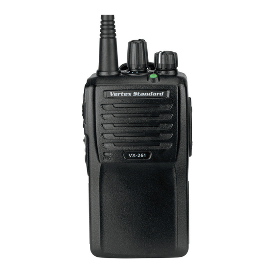
VX-261
o
m
Perating
anual
P
F
/F
rogrammable
unctions
eatures
IP55 Water Resistant
Two Programmable Function Keys
2-Tone Encode/Decode
5-Tone Encode/Decode
MDC-1200 ® Encode ( ANI Encode )
DTMF Encode
Scan
Dual Watch
Follow-Me Scan
Talk Around Scan
VOX
Talk Around
Emergency
Lone Worker
TX Save Disable
Lock
( Auto Range Transpond System )
ARTS™
Advertisement
Table of Contents

Related Manuals for Vertex Standard VX-261


Summary of Contents for Vertex Standard VX-261
- Page 1 VX-261 Perating anual rogrammable unctions eatures IP55 Water Resistant Two Programmable Function Keys 2-Tone Encode/Decode 5-Tone Encode/Decode MDC-1200 ® Encode ( ANI Encode ) DTMF Encode Scan Dual Watch Follow-Me Scan Talk Around Scan ...
-
Page 2: Table Of Contents
ontents Introduction..............1 Operation................ 10 Warning!.FCC.RF.Exposure.Requirements....2 Preliminary Steps ............10 Warning!.IC.RSS.General.Requirement....... 4 Operation Quick Start ..........10 Before.You.Begin.............. 6 Automatic Time-Out Timer ........12 Battery Pack Installation and Removal ....... 6 Advanced.Operation............13 Battery Charging ............6 Programmable Key Functions ........13 Low Battery Indication ..........7 Description of Operating Functions ...... -
Page 3: Introduction
The VX-261 is full-featured Hand-Held Analog Transceiver designed for business communications in the VHF/UHF Land Mobile bands. This transceiver is designed for reliable business communications in a wide variety of applications with a wide range of operating capability provided by their leading-edge design, and allows up to 16-channel capacity. Important channel frequency data is stored in the flash memory, and is easily programmable by a Vertex Standard licensed dealers using a personal computer with Vertex Standard Programming equipment: FIF-12 USB Programming Interface, and CT-106 Connection cable with CE150 PC Programming Software. Or, once a single radio is programmed, cloning cable CT-27 can be used to program additional radios directly. This manual will describe the details of the many advanced features of the VX-261. After reading this manual, you may wish to consult with your Network Administrator regarding precise details of the configuration of this equipment for use in your application. Important.Notice.for.North.American.Users.Regarding.406.MHz.Guard.Band The U.S. Coast Guard and National Oceanographic and Atmospheric Administration have requested the cooperation of the U.S. Federal Communications Commission in preserving the integrity of the protected frequency range 406.0 to 406.1 MHz, which is reserved for use by distress beacons. Do not attempt to program this apparatus, under any circumstances, for operation in the frequency range 406.0 - 406.1 MHz if the apparatus is to be used in or near North America. Warning - Frequency band 406 - 406.1 MHz is reserved for use ONLY as a distress beacon by the US Coast Guard and NOAA. Under no circumstance should this frequency band be part of the pre programmed operating frequencies of this radio. VX-261 O perating anual... - Page 4 .CAUTION: To ensure that your expose to RF electromagnetic energy is within the FCC allowable limits for occupational use, always adhere to the following guidelines: . This.radio.is.NOT.approved.for.use.by.the.general.population.in.an.uncontrolled.exposure.environment..This.ra- dio.is.restricted.to.occupational.use,.work.related.operations.only.where.the.radio.operator.must.have.the.knowl- edge.to.control.his.or.her.RF.exposure.conditions. . When. transmitting,. hold. the. radio. in. a. vertical. position. with. its. microphone. 1. inch. (2.5. cm). away. from. your. mouth.and.keep.the.antenna.at.least.1.inch.(2.5.cm).away.from.your.head. . Transmit.no.more.than.the.rated.duty.factor.of.50%.of.the.time..To.transmit.(talk),.push.the.Push-To-Talk.(PTT). button..To.receive.calls,.release.the.PTT.button..The.PTT.button.may.reside.on.the.radio.itself.or.may.be.hosted. VX-261 O perating anual...
-
Page 5: Warning!.Fcc.rf.exposure.requirements
! Fcc rF e arning xPosure equirements on.approved..accessories..Transmitting.50%.of.the.time,.or.less,.is.important.because.this.radio.generates.mea- surable.RF.energy.exposure.only.when.transmitting.(in.terms.of.measuring.for.standards.compliance). The.radio.is.transmitting.when.the.red.LED.on.the.top.of.the.radio.is.illuminated...You.can.cause.the.radio.to. transmit.by.pressing.the.P-T-T.button. . In.front.of.the.face..Hold.the.radio.in.a.vertical.position.with.the.microphone.(and.other.parts.of.the.radio.in- cluding.the.antenna).at.least.1.inch.(2.5.cm).away.from.the.nose.or.lips..Keeping.the.radio.at.a.proper.distance.is. important.to.ensure.compliance. . SAR.compliance.for.body-worn.use.was.only.demonstrated.for.the.specific.belt-clip.(CLIP-20)..Other.body-worn. accessories.or.configurations.may.NOT.comply.with.the.FCC.RF.exposure.requirements.and.should.be.avoided. . Always.use.Vertex.Standard.authorized.accessories. . The.information.listed.above.provides.the.user.with.the.information.needed.to.make.him.or.her.aware.of.RF.ex- posure,.and.what.to.do.to.assure.that.this.radio.operates.with.the.FCC.RF.exposure.limits.of.this.radio. . Electromagnetic.Interference/Compatibility During.transmissions,.this.radio.generates.RF.energy.that.can.possibly.cause.interference.with.other.devices.or. systems..To.avoid.such.interference,.turn.off.the.radio.in.areas.where.signs.are.posted.to.do.so. Do.not.operate.the.transmitter.in.areas.that.are.sensitive.to.electromagnetic.radiation.such.as.hospitals,.health. care.facilities,.aircraft,.and.blasting.sites. VX-261 O perating anual... -
Page 6: Warning!.Ic.rss.general.requirement
ATU-6F: −2.15 dBi, 50-ohm . When. transmitting,. hold. the. radio. in. a. vertical. position. with. its. microphone. 1. inch. (2.5. cm). away. from. your. mouth.and.keep.the.antenna.at.least.1.inch.(2.5.cm).away.from.your.head. . The.radio.must.be.used.with.a.maximum.operating.duty.cycle.not.exceeding.50%,.in.typical.Push-to-Talk.con- figurations. DO.NOT.transmit.for.more.than.50%.of.total.radio.use.time.(50%.duty.cycle)..Transmitting.more.than.50%.of. the.time.can.cause.IC.RSS.General.Requirement.to.be.exceeded..To.keep.the.Body.Worn.configuration.with.the. Vertex.Standard.CLIP-20.belt-clip,.reduce.the.maximum.operating.duty.cycle.still.more. The.radio.is.transmitting.when.the.red.LED.on.the.top.of.the.radio.is.illuminated...You.can.cause.the.radio.to. transmit.by.pressing.the.P-T-T.button. . SAR.compliance.for.body-worn.use.was.only.demonstrated.for.the.specific.belt-clip.(CLIP-20)..Other.body-worn. accessories.or.configurations.may.NOT.comply.with.the.IC.RSS.General.Requirement.and.should.be.avoided. VX-261 O perating anual... - Page 7 ATV-6XL: −2.15 dBi, 50-ohm ATU-6D: −2.15 dBi, 50-ohm est supérieur au gain maximal indiqué, sont strictement interdits pour ATU-6F: −2.15 dBi, 50-ohm l’exploitation de l’émetteur. . Pour.émettre,.tenez.votre.radio.verticalement.en.plaçant.le.microphone.entre.2,5.et.5.cm.de.la.bouche..L’antenne. doit.toujours.être.à.plus.de.2,5.cm.de.votre.tête. . . L e.temps.total.d’émission.de.la.radio.ne.doit.pas.dépasser.50%.du.temps.de.fonctionnement.dans.une.configuration. normale.avec.alternat..Par.conséquent,.vous.ne.devez.PAS.émettre.pendant.plus.de.50%.du.temps.total.d’utilisa- tion.de.la.radio..Si.cette.règle.n’est.pas.respectée,.vous.exposez.à.un.dépassement.de.l’exposition.aux.fréquences. électromagnétiques.telle.que.définie.par.la.norme.de.sécurité..La.radio.émet.lorsque.le.voyant.LED.rouge.(situé.au. sommet.de.la.radio).est.allumé..Vous.pouvez.déclencher.l’émission.en.appuyant.sur.le.bouton.Alternat.ou.avec.un. micro-casque.VOX,.si.la.radio.permet.d’utiliser.cet.accessoire. . La.conformité.SAR.pour.utilisation.sur.le.corps.n’a.été.confirmée.que.pour.l’attache.ceinture.de.nomenclature. CLIP-20..L’utilisation.de.tout.autre.accessoire.pour.port.sur.le.corps.PEUT.être.non.conforme.aux.normes.d’ex- position.aux.radio-fréquences.et.doit.donc.être.évitée. . N’opérez.pas.votre.radio.en.mode.d’émission.lorsque.vous.la.portez.fixée.sur.le.corps.à.l’aide.de.l’accessoire.sui- vant.:.CLIP-20.attache.ceinture. VX-261 O perating anual...
-
Page 8: Before.you.begin
CD-58; refer to the follow- ing illustration for details on proper positioning of the r To remove the battery, turn the radio off and remove any protective cases. Slide the Battery Pack Latch on the bottom of the radio toward the front panel while AC Line Outlet Spacer Plate sliding the battery down about 1/2 inch (1.5 cm). Then lift the battery out from the radio. Do.not.attempt.to.open.any.of.the.rechargeable. Lithium-Ion.packs,.as.they.could.explode.if.ac- cidentally.short-circuited. PA-55 CD-58 VX-261 O perating anual... -
Page 9: Low Battery Indication
UNI or FNB-V134LI-UNI Lithium-Ion Battery Danger of explosion if battery is replaced with an Pack. incorrect battery. Replace only with the same or 2) Use only the Vertex Standard CD-58 Desktop Charger equivalent type. and the Vertex Standard PA-55 AC Adapter. 3) To reduce the risk of explosion, recharge the batteries outside of hazardous locations. -
Page 10: Belt Clip Installation And Removal
Belt Clip Tab r Use. only. the. supplied. screws. when.install.the.MIC/SP cap. r This. radio. does. not. keep. the. Water. Resistant. Rating. (IP55). when.the.MIC/SP.cap.is.not.in- stalled.in.the.MIC/SP.jack. VX-261 O perating anual... -
Page 11: Controls.&.Connectors
CH ( Channel ) Selector VOL ( Volume ) /PWR ( Power ) Knob Antenna Jack LED Indicator ( Programmable ) Default settings are: Steady Red: Transmitting in progress Blinking Green: Busy Channel Steady Green: Tone Squelch in defeated condition Microphone Speaker PTT Switch MIC/SP Jack ( External MIC/SP ) SIDE-1 Button SIDE-2 Button Battery Pack Latch VX-261 O perating anual... -
Page 12: Operation
Selector knob to choose not be connected until you are the desired operating familiar with the basic opera- channel. tion of the VX-261. Refer to next page for more information about Speaker/Microphone us- age. r Rotate the VOL/PWR knob to set the volume IMPORTANT NOTE l e v e l . I f n o s i g n a l i s... - Page 13 2 button to activate one of the pre-programmed Microphone, it disables the internal microphone, and functions which may vice versa. r If the BCLO (Busy Channel Lockout) feature has been have been enabled at the programmed on a channel, the radio will not transmit time of programming by the dealer. See the next chapter for details regarding when a carrier is present. Instead, the radio will gener- feature availability for this radio. ate short beep three times. Release the PTT switch and wait for the channel to be clear of activity. VX-261 O perating anual...
-
Page 14: Automatic Time-Out Timer
LED (“TX” indicator) will disappear and transmission will cease soon thereafter. To resume transmitting, you must release the PTT switch and wait for the “penalty timer” to expire. VX-261 O perating anual... -
Page 15: Advanced.operation
Peration Programmable.Key.Functions rogrammable ress ress and The VX-261 provides two Programmable Function ( PF ) unction SIDE-1 SIDE-2 keys: SIDE-1 and SIDE-2 keys. None Monitor Both PF keys can be customized, via programming by Monitor -Momentarily- /--- /--- your Vertex Standard dealer, to meet your communica- Low Power tions/network requirements. -
Page 16: Description Of Operating Functions
Vox a SQL to hear background noise (unmute the audio). Press, (or press and hold), the assigned PF key to toggle sql oFF -m omentarilY the VOX Anti-Trip feature “On” and “Off”. Opens the SQL to hear background noise (unmute the au- dio) while pressing the assigned PF key. When the VOX Anti-Trip feature is set to “On”, the trans- ceiver does not activate a VOX transmission from picking up receive audio or from a radio alert tone (beep sound). Press, (or press and hold), the assigned PF key to dis- able any radio beeps temporarily. Press again, (or press and hold again), the assigned PF key to enable any radio beeps. VX-261 O perating anual... - Page 17 “Last Busy” channel switches to Emergency mode. “Priority” channel “User Programmed” channel (“Select Channel”) The channel which defined in the CH Selector Press, (or press and hold), the assigned PF key to recall knob. the pre-programmed Priority Channel by your Vertex Standard dealer directly. VX-261 O perating anual...
- Page 18 To stop Dual Watch: ority” channel. Next, press, (or press and hold), the as- r Press, (or press and hold), the assigned PF key to dis- signed PF key. Finally, rotate the CH Selector knob to the able the Dual Watch feature. The radio receives the desired “operating channel”. channel which was selected by the CH Selector knob. The scanner will search the two channels (user-assigned priority channel and operating channel) and pause when it finds a transmission on either channel. VX-261 O perating anual...
- Page 19 Around” channels by programming “repeater” and “Talk the transceiver will check for activity on the receive fre- Around” frequencies on two adjacent channels. If so, the quency every few seconds (interval programmed by your key may be used for one of the other Pre-Programmed Vertex Standard dealer). Functions. Note: The TA Scan feature does not activate on a Simplex Note: The Talk Around feature does not activate on a Sim- Channel. plex Channel. reset Press (or press and hold) the assigned PF key to reset the RFC (Ready for Communication) condition. Press, (or press and hold), the assigned PF key to send a pre-programmed 5-Tone call signal. VX-261 O perating anual...
- Page 20 Transmit Battery Saver activates to reduce the Press, (or press and hold), the assigned PF key to toggle transmit power when a very strong signal from an appar- the Duty function of the 2-Tone or 5-Tone “On” and “Off”. ently nearby station is being received. When the Duty function is set to “On”, the user will al- ways hear (depending on the sub-audio signaling) all traf- Press (or press and hold) the assigned PF key to lock the fic on the paging channel. The radio will sound the paging CH Selector knob, Programmable keys, and PTT switch. alert when it receives the programmed 2-Tone or 5-Tone. When the Duty function is set to “Off”, the user will NOT hear normal radio traffic on the paging channel. The radio will sound the paging alert and unmute only when it re- ceives the programmed 2-Tone or 5-Tone. VX-261 O perating anual...
-
Page 21: Lock
Programmable keys, and PTT switch may be are within communication range using the DCS Encoder/ locked. The precise lockout configuration is programmed Decoder. by your Dealer. During ARTS™ operation, when the radio receives an To activate the key locking, turn the radio off. Then, press incoming ARTS™ signal, a short beep will sound. If you and hold the PTT and SIDE-2 key while turning the radio move out of range for more than two minutes, your radio on again. senses that no signal has been received; a short triple-beep will sound. If you move back into communication range, To cancel the key locking, repeat this process. as soon as the other station transmits, a short beep will sound again. VX-261 O perating anual... -
Page 22: Optional.accessories
Availability of accessories may vary; some ac- CE150 PC Programming Software cessories are supplied standard per local re- FIF-12 USB Programming Interface quirements, others may be unavailable in some Connection Cable for FIF-12 CT-106 regions. Check with your Vertex Standard Dealer CT-27 Radio to Radio Cloning Cable for changes to this list. VX-261 O perating anual... - Page 23 arrantY olicY Vertex Standard warrants, to the original purchaser only, its Vertex Standard manufactured communications products against defects in materials and workmanship under normal use and service for a given period of time from the date of pur- chase. Limited Warranty Details: Ÿ North America customers (USA and Canada): http://www.vertexstandard.com/lmr/warranty-terms.aspx Ÿ Customers outside of North America: contact the authorized Vertex Standard distributor in your country. isposal your lEctronic lEctric quipmEnt Products with the symbol (crossed-out wheeled bin) cannot be disposed as household waste. Electronic and Electric Equipment should be recycled at a facility capable of handling these items and their waste by products.
- Page 24 Vertex Standard LMR, Inc. No portion of this manual may be reproduced without the per- mission of Vertex Standard LMR, Inc. 4-6-8 Shibaura, Minato-ku, Tokyo 108-0023, Japan Vertex Standard is a trademark of Vertex Standard LMR, Inc. All other trademarks are the property of their respective owners. ©2015 Vertex Standard LMR, Inc. All rights reserved.