Advertisement
Quick Links
2 or 4 pipe systems
Non-Programmable
Thermostat
Owner's Manual
model T701DFN-1
Fan Coil
Thermostat
Remote sensor ready
Self-prompting adjustment
Auto 2-pipe changeover
when used with accessory
changeover sensor
Dry contact equipped
Backlit display
TM
One For All
works with
most all fan coil systems
Electric heat ready
Non-volatile memory
Dual setpoint with
adjustable deadband
Keypad lockout
Configurable display
Display either F or C
Terminals on backplate
Advertisement

Related Manuals for Johnson Controls T701DFN-1


Summary of Contents for Johnson Controls T701DFN-1
-
Page 1: Fan Coil
T701DFN-1 Fan Coil Thermostat 2 or 4 pipe systems Remote sensor ready Non-Programmable Self-prompting adjustment Thermostat Auto 2-pipe changeover when used with accessory changeover sensor Dry contact equipped Backlit display One For All works with most all fan coil systems... -
Page 2: Selecting The Heat
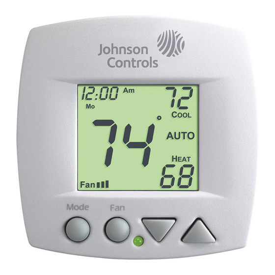
P/N T701DFN-1 North American Emissions Compliance United States This equipment has been tested and found to comply with the limits for a Class A digital device pursuant to Part 15 of the FCC Rules. These limits are designed to provide reasonable protection against harmful interference when this equipment is operated in a commercial environment. - Page 3 Front Panel AUTO Mode Liquid Crystal Display with Thermoglow Up/Down Buttons Mode Button Fan/Override Button Heat or Cool Indicator Heat = Red, Cool = Green Page 2...
- Page 4 Display unoccupied UTSIDE Mode Indicators - Page 5-8 Selects the operational mode of the equipment. HEAT - Indicates the heating mode. COOL - Indicates the cooling mode. AUTO - Indicates the system will automatically changeover between heat and cool modes as the temperature varies.
- Page 5 Display unoccupied UTSIDE icon - Page 9 Indicates fan operation. = low speed = medium speed = high speed When only the Fan icon is displayed, the fan is in the Auto mode and will run only when necessary to heat or cool.
- Page 6 Selecting the Heat or Cool Mode 4-Pipe Operation Select Mode by Pressing the MODE Button Heating Only The HEAT setting indicates the temperature that the room has to fall to before the heating source will turn on to heat the room. Press MODE Cooling Only...
- Page 7 Selecting the Heat or Cool Mode 2-Pipe Operation Heat Only Step #4 = 1 in the Advanced Setup section, page 11. Heating Only The HEAT setting indicates the temperature that the room has to fall to before the heating source will turn on to heat the room.
- Page 8 Selecting the Heat or Cool Mode 2-Pipe Operation Cool Only Step #4 = 2 in the Advanced Setup section, page 11. Cooling Only The COOL setting indicates the temperature that the room has to rise to before the cooling source will turn on to cool the room.
- Page 9 Selecting the Heat or Cool Mode 2-Pipe Operation Heating and/or Cooling Step #4 = 3 in Advanced Setup (page 11), and a changeover sensor is used. Step #4 = 4 or 5 in Advanced Setup (page 11). Operation is the same as a 4-pipe system (page 5). HEAT indicates the temperature that the room has to fall to before the heating source energizes.
- Page 10 Basic Operation Selecting Your Desired Temperature (adjusting the setpoints) AUTO OR PROGRAM MODE Pressing the UP or DOWN button in Auto or Program mode will adjust both the heat and cool set temperatures simultaneously. Adjust the desired set temperature with the AUTO buttons.
- Page 11 Advanced Setup NOTE: Each step Press the MODE and MODE # is located at the FAN buttons at the top right corner of same time for 10 the display for easy seconds to enter reference. A d v a n c e d S e t u p screens.
- Page 12 Advanced Setup Select fan coil system Setup type: 2 = 2-pipe fan coil 4 = 4-pipe fan coil Step #4 only appears if step #3 = 2. Press 2-PIPE SYSTEM OPERATION MODE 1= Heat only system 2= Cool only system Setup 3= Heat/Cool Auto changeover...
- Page 13 Advanced Setup Adjust the deadband Setup for the 1st stage. (1 - 6 ) See Page 17 Press Step #7 will not appear if step #4 = 1 or 2. MODE Adjust the minimum Setup difference between cooling & heating setpoints.
- Page 14 Advanced Setup Setup Select sensor operation: On = read only duct sensor UTSIDE Off = control to duct sensor Setup Dry Contact NO = Normally Open NC = Normally Closed See Page 18 Press MODE Unoccupied Setpoints Select Dry Contact Setup unoccupied Unoccupied operation:...
- Page 15 Advanced Setup Adjust the heating set- unoccupied point for Unoccupied periods. (OF, 35 - 99 ) After programming is complete, press the MODE and FAN buttons at the same time for two seconds to leave the Setup screens. If no buttons are pressed, the display will leave the setup screens after 30 seconds.
- Page 16 Advanced Setup Advanced Setup Table Step Factory Description Range Default Display Blanking On / Off Single or Dual Setpoint 1 / 2 2-or 4-Pipe System 2 / 4 2-Pipe System Operation 1 - 5 Fan Auto Operation On / Off Deadband/Temp.
- Page 17 About Advanced Features & Operation CALIBRATION - Under normal circumstances it will not be necessary to adjust the calibration of the temperature sensor. If calibration is required, please contact a trained HVAC technician to correctly perform the following procedure. MODE Place the thermostat in the OFF mode.
- Page 18 About Advanced Features & Operation DEADBAND OPERATION - Controls one Heat and one Cool stage with a three speed fan (see below). The low speed fan for heat or cool is turned on when: The temperature spread from the setpoint is equal to or greater than: the setpoint plus the 1st stage dead- band (step #6, page 12).
-
Page 19: Dry Contact Switch
About Advanced Features & Operation DRY CONTACT SWITCH - This feature allows an ex- ternal device such as a Central Time Clock, Occup- ancy Sensor, or a Telephone activated device to force one or more thermostats into an Unoccupied mode (steps #11 and 12, page 13). -
Page 20: Factory Defaults
About Advanced Features & Operation FACTORY DEFAULTS - If, for any reason, you desire to return all the stored settings back to the factory default settings, follow the instructions below. WARNING: This will reset all Advanced Program- ming to the default settings. Any information entered prior to this reset will be permanently lost. - Page 21 About Advanced Features & Operation FAN OPERATION - Fan operation is available in four different modes: Fan: When only the fan icon is displayed, this indicates that the fan is in the Auto mode, will only energize during a heating or cooling cycle, and will modulate fan speeds based on temperature demand (see page 17).
- Page 22 About Advanced Features & Operation HEAT/COOL DIFFERENTIAL - The Heat and Cool set- points will not be allowed to come any closer to each other than the value set in Advanced Setup step #7, on page 12. This minimum difference is enforced during Auto-changeover operation.
-
Page 23: Locking Cover
About Advanced Features & Operation LOCKING COVER w/Tamper Proof Screws AUTO OUTSIDE SENSOR - To view an Outside Sensor (step #10, page 13), press and hold the FAN button for two seconds until the Outside icon appears. If an optional outside sensor is connected, the outside temperature will appear on the display. - Page 24 About Advanced Features & Operation DUCT SENSOR (P/N SEN-700-1) - The thermostat is programmed from the factory to auto- matically recognize when a Duct Digital Sensor Sensor is connected (step #10, page 13). High Temp. Heat Shrink Tubing The Duct Sensor measures indoor air temperature and sends this infor- mation to the thermostat;...
- Page 25 About Advanced Features & Operation SINGLE SETPOINT BEHAVIOR - When configured for Single Setpoint operation (step #2, page 10), the degree icon will blink when the large number is display- ing room temperature and will remain solid when dis- playing the heating or cooling setpoint. In the Auto mode the deadband is enforced both above and below the setpoint.
- Page 26 P/N 88-822 Rev. 1H P.O. Box 423 • Milwaukee, WI 53201-0423 • 414.524.7349 [phone] • 414.524.5043 [fax] • www.jci.com ©2010 Johnson Controls Inc (JCI).