Table of Contents
Advertisement
Quick Links
Advertisement
Table of Contents

Related Manuals for B&B Electronics Elinx ESW500 Series


Summary of Contents for B&B Electronics Elinx ESW500 Series
-
Page 1: Quick Start Guide
Quick Start Guide Elinx ESW500 Series Managed Din Rail Ethernet Switch... - Page 2 ESW500 Series Documentation Number: ESW500series-1012qsg International Headquarters: 707 Dayton Road Ottawa, IL 61350 USA Phone (815) 433-5100 Website: www.bb-elec.com Sales e-mail: orders@bb-elec.com Technical Support: support@bb.elec.com – European Headquarters B&B Electronics Westlink Commercial Park Oranmore, Co. Galway, Ireland Phone +353 91-792444 Website: www.bb-europe.com Sales e-mail: sales@bb-europe.com Technical Support: support@bb-europe.com...
- Page 3 publication is for reference purposes only and does not constitute an endorsement by the trademark holder.
-
Page 5: Table Of Contents
Table of Contents OVERVIEW ..............1 Features ....................... 2 Package Check List ..................2 Front Panel – ESW508 Series ..............3 Front Panel - ESWG510 Series ..............4 Front Panel – ESW516 Series ..............5 LED Description ..................6 Mounting Options ..................7 INITIAL SETUP .............. - Page 6 Console Port (DB9 Male) ............... 16 Serial Cable Pin out ................16 Network Settings ..................17 Default Security ..................17 ESW500series-1012qsg Installation Guide Documentation Number: B&B Electronics Mfg Co Inc – 707 Dayton Rd - PO Box 1040 - Ottawa IL 61350 - Ph 815-433-5100 - Fax 815-433-5104 – www.bb-elec.com B&B Electronics –...
-
Page 7: Overview
Overview B&B Electronics Elinx family of Managed Industrial Din Rail mount Ethernet switches have been designed to meet light Industrial and commercial communication requirements. The ESW500 Managed Series offers a variety of Industrial models. The switch configurations range from 8 ports to 16 ports with all RJ45 copper to RJ45 copper with multi mode, single mode, and or SFP gigabit ports. -
Page 8: Features
Features Light Industrial and Commercial 61000-6-1 specifications -10 to 60°C or -40 to 75°C (-T models) temperature rating Supports IEEE 802.3 10Base-T,802.3u 100Base-TX IEEE 802.3z for 1000BaseSX/LX/LHX/ZX RJ-45 port supports auto MDI/MDI-X function SC Single mode and Multi mode fiber connectors ... -
Page 9: Front Panel - Esw508 Series
Front Panel – ESW508 Series Bottom View System Ready Redundant Power LED 10/100BaseT(X) RJ45 Ports Link LED Speed LED 100BaseFX, SC Fiber Port Fiber Link, Activity LED Console Port Fault Relay 10. Ground Screw 11. Input Power Terminal Block ESW500series-1012qsg Installation Guide Documentation Number: B&B Electronics Mfg Co Inc –... -
Page 10: Front Panel - Eswg510 Series
Front Panel - ESWG510 Series Bottom View System Ready Power LED 10/100BaseT(X) RJ45 Ports Speed LED Link LED Fiber Link, Activity LED 100BaseFX, SC Fiber Port Input Power Terminal Block Ground Screw 10. Console Port 11. Combo RJ45 or SFP Port 12. -
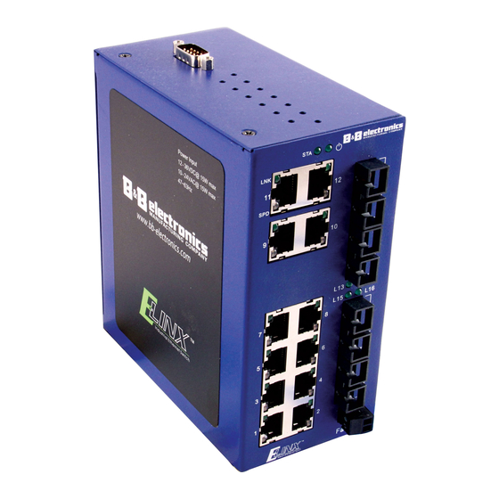
Page 11: Front Panel - Esw516 Series
Front Panel – ESW516 Series Bottom View Console Port System Ready Power LED 10/100BaseT(X) RJ45 Ports Link LED Speed LED Fiber Link, Activity LED 100BaseFX, SC Fiber Port Fault Relay 10. Ground Screw 11. Input Power Terminal Block ESW500series-1012qsg Installation Guide Documentation Number: B&B Electronics Mfg Co Inc –... -
Page 12: Led Description
LED Description Status Description Green Power Applied No power Green System Ready System down Green 100Mbps 10/100 Copper SPD LED 10Mbps Green Link Blinking Activity 10/100 Copper LNK LED Not connected to network Green Link Blinking Activity Fiber LED Not connected to network Green 1000Mbps Combo Port 10/100/1000 Copper SPD... -
Page 13: Mounting Options
Mounting Options Initial Setup Getting Started The Managed Ethernet switch can be accessed, configured and managed via a Web server using a web browser. Before this operation can be implemented it may be necessary to configure the switch’s IP address via HyperTerminal or to change the IP address of the connected PC. -
Page 14: Console Mode
(2) The default IP address of the Managed Ethernet switch is: 192.168.118.100. Set your PC's IP address to 192.168.118.X (X is any value from 2 to 254 except 100), Subnet Mask: 255.255.255.0, and Gateway: 192.168.118.1 (3) Open the web browser and enter the default IP address: 192.168.118.100 in the address bar. -
Page 15: Console Menu
The default username and password are "admin". Console Menu The console menu includes: Overview, IP Settings, Factory Default and Logout. Move the arrow key up or down to select different items. Press the selected function to "Enter" view configuration options. IP address Configuration The IP Setting options offer two methods of network configuration, Static and DHCP. -
Page 16: Ports
Ports RJ45 The RJ45 copper ports support auto MDI/MDIX operation. This feature allows network connections to computers, servers, or other switches using straight-through or crossover cables (See Figure below). Straight-through cable connections: pins 1, 2, 3 and 6, at one end of the cable, are connected straight-through to pins 1, 2, 3 and 6 at the other end of the cable. - Page 17 ESW500series-1012qsg Installation Guide Documentation Number: B&B Electronics Mfg Co Inc – 707 Dayton Rd - PO Box 1040 - Ottawa IL 61350 - Ph 815-433-5100 - Fax 815-433-5104 – www.bb-elec.com B&B Electronics – Westlink Commercial Park – Oranmore, Galway, Ireland – Ph +353 91-792444 – Fax +353 91-792445 – www.bb-europe.com...
-
Page 18: Gigabit Copper/Sfp (Mini-Gbic) Combo Ports
Gigabit Copper/SFP (mini-GBIC) COMBO ports The ESW500 series can be ordered with up to two auto-detect Gigabit combo copper/SFP combo ports. The Gigabit Copper (10/100/1000Mbps) ports use Category 5e or above UTP/STP cable for connection. The SFP slots can be used to connect the network segment with single or multi-mode fiber. -
Page 19: Sfp Installation And Connection
SFP Installation and Connection The SFP module is terminated with LC connectors. For installation, the module needs to be adjusted so as to be aligned correctly and then moved into the SFP slot until a click is heard. SFP Module Inserted ESW500series-1012qsg Installation Guide Documentation Number: B&B Electronics Mfg Co Inc –... -
Page 20: Cabling
LC Fiber Cable Connection To remove SFP modules lower removal bar and firmly pull transceiver out. Cabling Use unshielded twisted-pair (UTP) or shielded twisted-pair (STP) cable. ESW500series-1012qsg Installation Guide Documentation Number: B&B Electronics Mfg Co Inc – 707 Dayton Rd - PO Box 1040 - Ottawa IL 61350 - Ph 815-433-5100 - Fax 815-433-5104 – www.bb-elec.com B&B Electronics –... -
Page 21: 100Base Fx Sc Fiber
10Mbps: Category 3, 4, 5 or great cable 100Mbps: Category 5 or great cable 1000Mbps: Category 5e or great cable Maximum cable length: 100 meters (328ft.) 100Base FX SC Fiber The use of fiber optics has become prevalent in Industrial Ethernet network communication systems. -
Page 22: Dc / Ac Power Connections
DC / AC Power Connections ESW508 / ESW516 Series ESW510 Series Fault Relay Relay (Normally Open) Default Settings Console Port (DB9 Male) Serial baud rate: 115200 Data Bits: 8 Parity: NONE Stop bits: 1 Flow Control: NONE Serial Cable Pin out PC Serial Console Port Port DB 9... -
Page 23: Network Settings
Network Settings IP address: 192.168.118.100 Subnet Mask: 255.255.255.0 Gateway: 192.168.118.1 Default Security User Name: admin Password: admin VLAN All Ports are members of VLAN 1 (Management VLAN) ESW500series-1012qsg Installation Guide Documentation Number: B&B Electronics Mfg Co Inc – 707 Dayton Rd - PO Box 1040 - Ottawa IL 61350 - Ph 815-433-5100 - Fax 815-433-5104 – www.bb-elec.com B&B Electronics –...