
Related Manuals for B&B Electronics Elinx EIRP305-T


Summary of Contents for B&B Electronics Elinx EIRP305-T
- Page 1 Manual Documentation Number EIRP305-T – 0912m www.bb-elec.com www.bb-europe.com...
- Page 2 International B&B Electronics Mfg. Co. Inc. 707 Dayton Road Ottawa, IL 61350 USA Phone (815) 433-5100 -- General Fax (815) 433-5105 Website: www.bb-elec.com European Headquarters B&B Electronics Ltd. Westlink Commercial Park Oranmore, Co. Galway, Ireland Phone +353 91-792444 -- Fax +353 91-792445 Website: www.bb-europe.com ©2008 B&...
-
Page 3: Table Of Contents
Table of Contents Content Introduction......................1 Features......................1 Package Contents ....................1 Hardware Description ..................2 Physical Dimension....................2 Front Panel ......................2 Top View......................2 LED Indicators ....................3 Ports ........................3 Cabling .......................5 Wiring the Power Inputs ..................6 Wiring the Fault Alarm Contact.................7 Mounting Installation ..................8 DIN-Rail Mounting ....................8 Wall Mount Plate Mounting ................10 Hardware Installation ..................11 Installation Steps ....................11... -
Page 4: Introduction
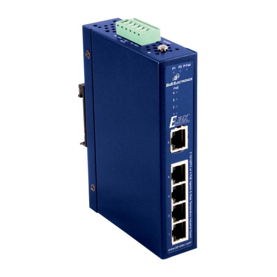
Introduction Introduction The EIRP305-T is an industrial DIN mount, unmanaged 5 port Ethernet Switch with 4 PoE Injector ports. All ports support 10/100Mbps speeds. Features • System Interface/Performance o RJ-45 ports support Auto MDI/MDI-X Function o Embedded 4-port PoE Injection o Store-and-Forward Switching Architecture o Back-plane (Switching Fabric): 1.0Gbps o 2K MAC Address Table... -
Page 5: Hardware Description
Hardware Description Hardware Description Physical Dimension (W x D x H) is 30mm x 95mm x 140mm (1.2 x 3.7 x 5.5 inches) Front Panel The Front Panel view of the EIRP305-T is shown below. Top View The top panel view of the EIRP305-T is equipped with one terminal block connector that consists of two 48 VDC power inputs and the fault alarm output. -
Page 6: Led Indicators
Hardware Description LED Indicators Below is a table that explains the status of each of the power and network status LED’s found on the front panel of the EIRP305-T. Color Description Power input 1 is active Green Power input 1 is inactive Power input 2 is active Green Power input 2 is inactive... - Page 7 Hardware Description All ports on the EIRP305-T support automatic MDI/MDI-X operation, you can use straight- through cables (See Figure below) for all network connections to PCs or servers, or to other switches or hubs. In straight-through cables, pins 1, 2, 3, and 6, at one end of the cable, are connected straight through to pins 1, 2, 3 and 6 at the other end of the cable.
-
Page 8: Cabling
Hardware Description Cabling Use unshielded twisted-pair (UTP) or shielded twisted-pair (STP) cable. 10Mbps: Use category 3, 4, 5 or greater cable 100Mbps: Use category 5 or greater Cable distances should be less than 100 meters (328 ft.) long. Manual Documentation Number EIRP305-T – 0912m www.bb-elec.com www.bb-europe.com... -
Page 9: Wiring The Power Inputs
Hardware Description Wiring the Power Inputs Follow the steps below to insert the power wires. Insert the positive and negative wires into the V+ and V- contacts on the terminal block connector. Tighten the wire-clamp screws to prevent the wires from becoming loose. Manual Documentation Number EIRP305-T –... -
Page 10: Wiring The Fault Alarm Contact
Hardware Description Wiring the Fault Alarm Contact The fault alarm contact is in the middle of terminal block connector as the picture shows below. If one of the power sources fails a fault will be detected causing the circuit to open. Insert the wires into the fault alarm contact. -
Page 11: Mounting Installation
Mounting Installation Mounting Installation DIN-Rail Mounting The DIN rail clip comes screwed on to the switch, from the factory. If the DIN rail clip is not screwed on the switch, please see the following figure to re-attach the DIN-Rail clip. Then follow the steps below to hang the switch onto a DIN rail. - Page 12 Network Application First, insert the top of DIN rail clip onto the piece DIN rail track. Then, lightly push the bottom of the switch so it can snap the rest of the way onto the DIN rail track. Check that the switch is held tightly to the DIN rail track. To remove the switch from the track, reverse the steps above.
-
Page 13: Wall Mount Plate Mounting
Network Application • Pulling slowly at the bottom of the switch will bring the switch out so that the switch can now be carefully lifted off the DIN rail track. Wall or Panel Mount Plate Mounting Follow the steps below to mount the industrial switch with wall mount plate. 1. -
Page 14: Hardware Installation
Network Application Hardware Installation Installation Steps 1. Unpack the switch. 2. Check that the DIN rail is screwed onto the switch. If the DIN rail clip is not screwed onto the switch. Please refer to DIN-Rail Mounting section for DIN-Rail installation. If you want to wall or panel mount the switch, then please refer to Wall or Panel Mount Plate Mounting. -
Page 15: Network Application
Network Application Network Application Control Center Core/Upper Level Switch Fiber Cable Up-Link IP Camera Wireless AP VOIP Phone IEEE 802.3af Compliant Powered Devices Manual Documentation Number ElRP305-T- 0912m bb-elec.com 'MMN. bb-europe.com 'MMN. -
Page 16: Troubleshooting
Troubleshooting Troubleshooting • Verify that you are using a 48VDC power supply. Applying more than 48VDC could cause damage to the switch. • Be sure the proper cable is used in your network. Refer to the Cabling section of this manual for help. -
Page 17: Technical Specification
Technical Specification Technical Specification IEEE 802.3 10Base-T Ethernet IEEE 802.3u 100Base-TX Fast Ethernet Standard IEEE802.3x Flow Control and Back Pressure IEEE802.3af Power over Ethernet CSMA/CD Protocol 14,880 pps for 10Base-T Ethernet port Transfer Rate 148,800 pps for 100Base-TX Fast Ethernet port MAC Address 2K MAC address table 10/100TX: 5 x RJ-45 with auto MDI/MDI-X function;... - Page 18 Technical Specification 10Base-T: 2-pair UTP/STP Cat. 3, 4, 5, 5e cable EIA/TIA-568 100-ohm (100m) Network Cable 100Base-TX: 2-pair UTP/STP Cat. 5/5e cable EIA/TIA-568 100-ohm (100m) Redundant 48VDC with removable terminal block Power Supply Power Consumption 3.4Watts (without PoE); 57 Watts (Full load with PoE) DIN rail kit for DIN-type cabinet install and wall-mount ear Installation for wall mounting...
- Page 19 Technical Specification IEC60068-2-32 (Free fall) IEC60068-2-27 (Shock) Stability testing IEC60068-2-6 (Vibration) Manual Documentation Number EIRP305-T – 0912m www.bb-elec.com www.bb-europe.com...