
Related Manuals for Pioneer GM-D1004


Summary of Contents for Pioneer GM-D1004
- Page 1 CLASS D FOUR-CHANNEL AMPLIFIER AMPLIFICATEUR 4 CANAUX CLASSE-D AMPLIFICADOR 4 CANALES CLASE D GM-D1004 Owner’s Manual Mode d’emploi Manual de instrucciones...
-
Page 2: Before You Start
Section Before you start Thank you for purchasing this PIONEER and receiver. product - Connect the equipment into an outlet on a cir- cuit different from that to which the receiver is connected. To ensure proper use, please read through this - Consult the dealer or an experienced radio/TV manual before using this product. -
Page 3: Visit Our Website
Section Before you start Visit our website Before connecting/ installing the amplifier http://www.pioneerelectronics.com in Canada WARNING http://www.pioneerelectronics.ca ! Handling the cord on this product or cords as- ! Learn about product updates (such as firm- sociated with accessories sold with the pro- ware updates) for your product. - Page 4 Section Before you start ! When installing the amplifier, do not allow ! The amplifier will reduce the power output if parts such as extra screws to get caught be- the temperature inside the amplifier gets tween the amplifier and the automobile. high.
-
Page 5: Setting The Unit
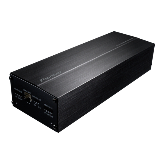
! Despite turning down the volume of the head unit, the unit sound still cuts out peri- odically. In such cases, please contact the nearest authorized Pioneer Service Station. To adjust the switch, use a flathead screwdri- ver if needed. -
Page 6: Connecting The Units
Section Connecting the units e Violet/black Connection of power cord f Black (chassis ground) and speaker Connect to a clean, paint-free metal location. g Yellow CAUTION Connect to the constant 12 V supply terminal. Connect the yellow cord to the terminal linked to h Blue/white the fuse unit of the car. -
Page 7: About Suitable Specification Of Speaker
The speaker output mode can be four-channel, ! For any further enquiries, contact your local three-channel (stereo and mono) or two-chan- authorized Pioneer dealer or customer nel (stereo or mono). Connect the speaker service. leads based on the mode and the figures... - Page 8 Section Connecting the units a Rear speaker output (Mono) Four-channel output Two-channel output (Stereo) 1 Green/black: Rear SP , Left * 2 White: Front SP , Left + 3 Gray/black: Front SP, Right * 4 Violet: Rear SP , Right + 5 Speaker (Left) 1 White/black: Front SP , Left * 6 Speaker (Right)
-
Page 9: Connections When Using The Rca Input Jack
Section Connecting the units Connections when using the RCA input jack Connect the car stereo RCA output jack and the RCA input jack of the amplifier. ! Do not connect the speaker to the car stereo for speaker output while using RCA input jack. - Page 10 Section Connecting the units 5 RCA cables (sold separately) 6 Car stereo with RCA front output jacks 7 Car stereo with RCA rear output jacks Two-channel input (Stereo) / (Mono) ! Slide INPUT SELECT (input select) switch to 2CH position. ! Connect to the RCA front input when using it in two-channel mode.
-
Page 11: Connections When Using The Speaker Input Wire
Section Connecting the units 4 RCA cable (sold separately) 4 Car Stereo or navigation system 5 Car stereo with RCA output jacks Note If speaker input wires from a head unit are con- nected to this amplifier, the amplifier will automa- Connections when using tically turn on when the head unit is turned on. -
Page 12: Before Installing The Amplifier
Section Installation ! The optimal installation location differs de- Before installing the amplifier pending on the car model. Secure the ampli- WARNING fier at a sufficiently rigid location. ! Check all connections and systems before ! To ensure proper installation, use the supplied final installation. - Page 13 Section Installation Install the amplifier with the use of supplied tapping screws (4 mm × 18 mm (1/8 in. × 3/4 in.)). 1 Tapping-screws (4 mm × 18 mm (1/8 in. × 3/4 in.)) 2 Floor mat or chassis 3 Drill a 2.5 mm (1/8 in.) diameter hole. Notes ! Do not install the cords in places where they touch the legs of a person as a disconnection...
-
Page 14: Additional Information
Appendix Additional information Specifications Power output ......45 W RMS × 4 Channels (at 14.4 V, 4 W and ≦ 1 % THD Power source ......14.4 V DC (10.8 V to 15.1 V allowable) S/N ratio ........74 dBA (reference: 1 W into 4 W) Grounding system .... - Page 15 PIONEER ELECTRONICS OF CANADA, INC. 340 Ferrier Street, Unit 2, Markham, Ontario L3R 2Z5, Canada TEL: 1-877-283-5901 TEL: 905-479-4411 PIONEER ELECTRONICS DE MEXICO, S.A. de C.V. Blvd.Manuel Avila Camacho 138 10 piso Col.Lomas de Chapultepec, Mexico, D.F. 11000 TEL: 55-9178-4270 先鋒股份有限公司...