Table of Contents
Advertisement
INSTALLER: LEAVE THESE INSTRUCTIONS WITH THE APPLIANCE THIS TERMINAL IS SERVING.
CONSUMER: RETAIN THESE INSTRUCTIONS FOR FUTURE REFERENCE. THESE INSTRUCTIONS
ARE TO BE USED IN CONJUNCTION WITH THE APPLIANCE AND PVA INSTRUCTIONS.
CERTIFIED UNDER CANADIAN AND AMERICAN NATIONAL STANDARDS: ANSI Z21.88 CSA 2.33 FOR VENTED GAS FIREPLACE HEATERS
GAS POWER
VENT (GPV)
GENERAL INFORMATION
These Installation Instructions must be used in conjunction
with the appliance and appropriate PVA adapter kit Installation
Instructions. Clearances listed in these Instructions supersede
those in the appliance's Installation Instructions.
Power venting of direct vent appliances may result in the
reduction of efficiencies by as much as ten percent. Consider
this in making any venting and heating decisions in any
installation application.
SELECTING AND INSTALLING THE APPLIANCE
When selecting a gas appliance for use with the GPV, take into
consideration the various requirements and limitations in the
venting installation section for the following models:
Models Equipped with an Intermittent Pilot Ignition (I.P.I.)
It is recommended that the GPV be used with a gas appliance
equipped with an Intermittent Pilot Ignition (I.P.I.). Downward
vertical vent runs are permitted with an I.P.I. system. See
venting section in appropriate PVA Installation Instructions.
Models Equipped with Millivolt/ Standing Pilot
Downward vertical vent runs are not permitted with a standing
pilot system. See venting section in appropriate PVA Installation
Instructions.
INSTALLATION TO BE DONE BY A QUALIFIED INSTALLER
to conform with local codes. In absence of local codes install
to the current National Building Code in Canada or to regional
building codes in the United States. It must be electrically
connected and grounded in accordance with local codes. In
the absence of local codes, use the current CSA C22.1
CANADIAN ELECTRICAL CODE in Canada or the ANSI/NFPA
70 NATIONAL ELECTRIC CODE in the United States.
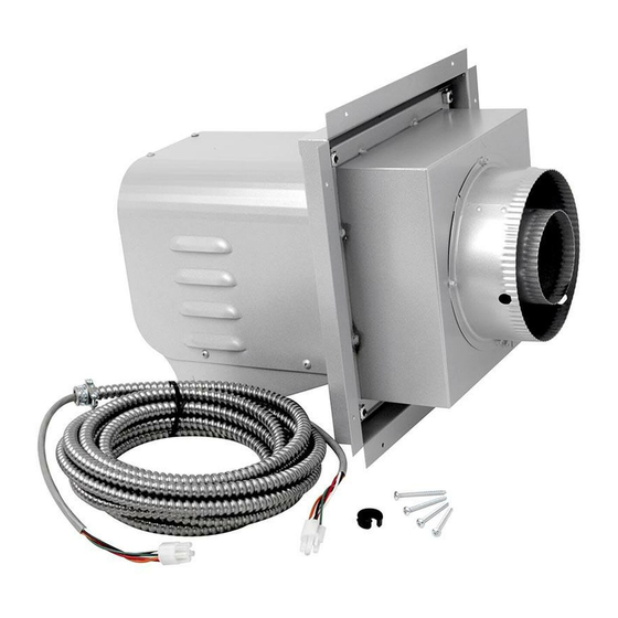
The GPV operates on 120 VAC 60 HZ electrical service which is
supplied at the firebox junction box.
Wolf Steel Ltd., 24 Napoleon Rd., Barrie, ON, L4M 4Y8 Canada /
INSTALLATION
INSTRUCTIONS
configurations cannot be achieved.
103 Miller Drive, Crittenden, Kentucky, USA, 41030
The GPV is a Direct Vent Terminal
designed to allow installation of
gas appliances where typical vent
1
EN
C E R T I F I E D
W415-1160 / 03.06.13
Advertisement
Table of Contents

Related Manuals for Napoleon GPV GAS POWER VENT


Summary of Contents for Napoleon GPV GAS POWER VENT
-
Page 1: General Information
The GPV operates on 120 VAC 60 HZ electrical service which is supplied at the firebox junction box. C E R T I F I E D Wolf Steel Ltd., 24 Napoleon Rd., Barrie, ON, L4M 4Y8 Canada / 103 Miller Drive, Crittenden, Kentucky, USA, 41030 W415-1160 / 03.06.13... -
Page 2: Table Of Contents
There are specifi c adaptors and venting requirements for each appliance, refer to your power vent adaptor leafl et for more information. For complete installation instructions refer to the following web sites: Manufacturer Website Napoleon - English http://www.napoleonfi replaces.com/Tech/installation_manuals/installations.html Napoleon - French http://www.napoleonfoyers.com/Fireplaces/powervent.html Continental http://www.continentalfi... -
Page 3: Installation Overview
INSTALLATION OVERVIEW Reducer, refer to A typical vent power vent configuration adapter kit (PVA) for specific vent- ing instructions where applicable. 0 I l l u s Firestop t r a t Spacer Electrical Box Gas Power (velcro to base) Vent Terminal Frame Assembly Terminal... -
Page 4: Vent Terminal Clearances
VENT TERMINAL CLEARANCES COVERED BALCONY APPLICATIONS ††* = 3 feet = 2 x ACTUAL (4.6m) (0.9m) INSTALLATIONS CANADA U.S.A. 12” 12” Clearance above grade, veranda porch, deck or balcony. (304.8mm) (304.8mm) 12” 9” (228.6mm) Clearance to windows or doors that open. (304.8mm) Δ... -
Page 5: Vent Lengths
VENT LENGTHS REFER TO POWER VENT ADAPTER KIT (PVA) FOR SPECIFIC VENTING INSTRUCTIONS. NOTE: If equipped, ACS switch must be disabled if there is any downward venting. Downward venting is not allowed with appliances that use standing pilots. POWER VENT TERMINAL 1.4.1 TERMINAL INSTALLATION This application occurs when venting through an exterior wall. -
Page 6: Power Vent Installation
1.4.2 POWER VENT INSTALLATION Stretch the inner fl ex pipe to the required length taking into account the additional length needed for the CAULKING fi nished wall surface. Slip the vent pipe a minimum of 3” (76.2mm) over the inner sleeve of the terminal and secure with 3 #8 screws. -
Page 7: Electrical Connection
1.4.4 ELECTRICAL CONNECTION WARNING DO NOT USE THIS APPLIANCE IF ANY PART HAS BEEN UNDER WATER. CALL A QUALIFIED SERVICE TECHNICIAN IMMEDIATELY TO HAVE THE APPLIANCE INSPECTED FOR DAMAGE TO THE ELECTRICAL CIRCUIT. RISK OF ELECTRICAL SHOCK OR EXPLOSION. DO NOT WIRE 110V TO THE VALVE OR TO THE APPLIANCE WALL SWITCH. -
Page 8: Electrical Box Installation
1.4.7 ELECTRICAL BOX INSTALLATION NOTE: Before fi nishing in the appliance, the power vent must be installed. LHD50 ILLUSTRATED BX SNAP BUSHING POWER VENT 20’ (6.1m) CONTROL POWER VENT MODULE CABLE SPLIT BUSHING JUNCTION BOX CONTROL MODULE REQUIRED Start by removing the pre-fi nishing access panel or opening lower louvre. Position the Power Vent Control Module in a convenient location (not on top of the heat shield in the LHD50) and Velcro it to the base of the appliance. -
Page 9: Sit Ipi 885 Proflame
1.6.1 SIT IPI 885 PROFLAME 1 Disconnect the wires labeled ON/OFF (White/Green) and TH (Green). Reconnect them to the corresponding male/female connectors on the Power vent control module. Disconnect the two D/C (Red/Black) wires from each other and reconnect them to the corresponding D/C connectors on the Power vent control module. -
Page 10: Sit Ipi Proflame 2
1.6.2 SIT IPI PROFLAME 2 Disconnect the (yellow/green) ground wire from the valve and connect it to the (green) ground wire, with piggy back connector, from the PVCM and then reconnect to the valve. Disconnect the (orange) wire from the valve and connect it to the (yellow) wire, with male end, from the PVCM. -
Page 11: Sit Millivolt 820 Requiring A Double Pole Switch
1.6.3 SIT MILLIVOLT 820 REQUIRING A DOUBLE POLE SWITCH NOTE: Must use double pole switch (supplied) or double pole thermostat (not supplied) with specifi c power vent adaptor kit. NOTE: Downward venting is not allowed with appliances that use a standing pilot. Connect the jumper wires to tabs TP/TH and TH on the gas valve. -
Page 12: Sit Millivolt 820 Nova For Single Pole Switch
1.6.4 SIT MILLIVOLT 820 NOVA FOR SINGLE POLE SWITCH NOTE: Downward venting is not allowed with appliances that use standing pilots. PILOT BURNER THERMOPILE THERMOCOUPLE Pilot Assembly SIT Millivolt Gas Valve WHITE BLOWER YELLOW YELLOW Power Vent VAC SWITCH Control Module YELLOW YELLOW... -
Page 13: Sit Millivolt 820 Nova Remote Controlled System Requiring Adouble Pole Switch
1.6.5 SIT MILLIVOLT 820 NOVA REMOTE CONTROLLED SYSTEM REQUIRING A DOUBLE POLE SWITCH NOTE: Must use double pole switch (supplied) or double pole thermostat (not supplied) with specifi c power vent adaptor kits. NOTE: Downward venting is not allowed with appliances that use standing pilots. PILOT BURNER THERMOPILE... -
Page 14: Sit Ipi 880/886 Proflame Requiring A Double Pole Switch
1.6.6 SIT IPI 880/886 PROFLAME REQUIRING A DOUBLE POLE SWITCH NOTE: Must use double pole switch (supplied) or double pole thermostat (not supplied) with specifi c power vent adaptor kit. Connect the jumper wires to the wire labeled ON/OFF (Green/White) and the wire labelled TH (Green). Connect the other end of the jumper wires to the Yellow wires from the Power vent control module. -
Page 15: Sit Ipi 880/886 For Single Pole Switch
1.6.7 SIT IPI 880/886 FOR SINGLE POLE SWITCH Connect the jumper wires to the wire labeled ON/OFF (Green/White) and the wire labelled TH (Green). Connect the other end of the jumper wires to the Yellow wires from the Power vent control module. DC BACK-UP GREEN (NOT ALLOWED... -
Page 16: Dexen Ipi 6003-3V Requiring A Double Pole Switch
1.6.8 DEXEN IPI 6003-3V REQUIRING A DOUBLE POLE SWITCH NOTE: Must use double pole switch (supplied) or double pole thermostat (not supplied) with specifi c power vent adaptor kit. NOTE: Downward venting is not allowed with appliances that use a standing pilot. Connect the Brown wires from the Ignition module to the yellow wires from the Power vent control module. -
Page 17: Dexen Ipi 6003-3V Requiring A Single Pole Switch
1.6.9 DEXEN IPI 6003-3V REQUIRING A SINGLE POLE SWITCH NOTE: Downward venting is not allowed with appliances that use a standing pilot. Connect the Brown wires from the Ignition module to the yellow wires from the Power vent control module. Ignition Module Ignitor ORANGE... -
Page 18: Adjustments
2.0 ADJUSTMENTS VENTURI ADJUSTMENTS REFER TO PVA KIT FOR SPECIFIC APPLIANCE INSTRUCTIONS. 3.0 REPLACEMENTS Contact your dealer or the factory for questions concerning prices and policies on replacement parts. Normally all parts can be ordered through your Authorized dealer / distributor. WARNING FOR WARRANTY REPLACEMENT PARTS, A PHOTOCOPY OF THE ORIGINAL INVOICE WILL BE REQUIRED TO HONOUR THE CLAIM. -
Page 19: Troubleshooting
4.0 TROUBLESHOOTING WARNING ALWAYS LIGHT THE PILOT WHETHER FOR THE FIRST TIME OR IF THE GAS SUPPLY HAS RAN OUT, WITH THE GLASS DOOR OPEN OR REMOVED. IN SOME INSTANCES THE SYSTEM MAY NOT LIGHT PILOT/BURNER WITH THE DOOR OPEN/ REMOVED. -
Page 20: Notes
5.0 NOTES 44.1 W415-1160 / 03.06.13...