Advertisement
Table of Contents
- 1 Table of Contents
- 2 Warning Decal Placement
- 3 Important Precautions
- 4 Before You Begin
- 5 Assembly
- 6 5) Around the Upright (4) until You Complete
- 7 How to Use the Exercise Bike
- 8 Maintenance and Troubleshooting
- 9 Exercise Guidelines
- 10 Part List
- 11 Exploded Drawing
- 12 Frame
- 13 Ordering Replacement Parts
- 14 Limited Warranty
- Download this manual
Model No. NTCCEX03810.1
Serial No.
Write the serial number in the
space above for reference.
Serial Number
QUESTIONS?
If you have questions, or if parts are
damaged or missing, PLEASE
CONTACT OUR CUSTOMER SER-
VICE DEPARTMENT DIRECTLY.
1-888-936-4266
CALL TOLL-FREE:
Mon.–Fri., 7:30 until 16:30 ET
(excluding holidays)
OR E-MAIL US:
customerservice@iconcanada.ca
CAUTION
Read all precautions and instruc-
tions in this manual before using
this equipment. Keep this manual
for future reference.
Decal
USER'S MANUAL
www.nordictrack.com
Advertisement
Table of Contents

Related Manuals for NordicTrack GX4.0 NTCCEX03810.1


Summary of Contents for NordicTrack GX4.0 NTCCEX03810.1
- Page 1 CONTACT OUR CUSTOMER SER- VICE DEPARTMENT DIRECTLY. CALL TOLL-FREE: 1-888-936-4266 Mon.–Fri., 7:30 until 16:30 ET (excluding holidays) OR E-MAIL US: customerservice@iconcanada.ca CAUTION Read all precautions and instruc- tions in this manual before using this equipment. Keep this manual for future reference. www.nordictrack.com...
-
Page 2: Table Of Contents
If a decal is missing or illegible, see the front cover of this manual and request a free replacement decal. Apply the decal in the location shown. Note: The decal(s) may not be shown at actual size. NORDICTRACK is a registered trademark of ICON IP, Inc. -
Page 3: Important Precautions
IMPORTANT PRECAUTIONS WARNING: To reduce the risk of serious injury, read all important precautions and instructions in this manual and all warnings on your exercise bike before using your exercise bike. ICON assumes no responsibility for personal injury or property damage sustained by or through the use of this product. -
Page 4: Before You Begin
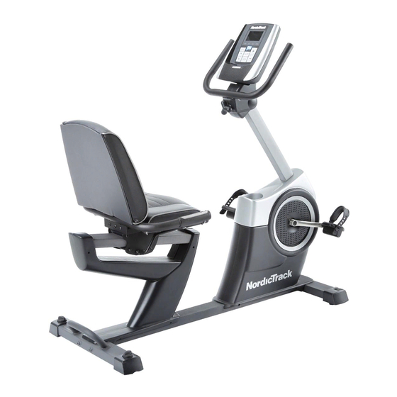
BEFORE YOU BEGIN Thank you for selecting the revolutionary after reading this manual, please see the front cover NORDICTRACK GX 4.0 exercise bike. Cycling is an of this manual. To help us assist you, note the product ® effective exercise for increasing cardiovascular fitness, model number and serial number before contacting building endurance, and toning the body. -
Page 5: Assembly
ASSEMBLY Assembly requires two persons. Place all parts of the exercise bike in a cleared area and remove the packing materials. Do not dispose of the packing materials until assembly is completed. In addition to the included tool(s), assembly requires a Phillips screwdriver and an adjustable wrench See the drawings below to identify the small parts needed for assembly. - Page 6 To make assembly easier, read the information on page 5 before you begin. While a second lifts the front of the Frame (1), attach the Front Stabilizer (2) to the Frame with two M10 x 95mm Patch Screws (62). 2. While a second lifts the rear of the Frame (1), attach the Rear Stabilizer (3) to the Frame with two M10 x 95mm Patch Screws (62).
-
Page 7: 5) Around The Upright (4) Until You Complete
3. Slide the Shield Cover (5) upward onto the Upright (4). Avoid pinching the wires Have a second person hold the Shield Cover (5) around the Upright (4) until you complete step 4. Tip: Avoid pinching the wires inside the Frame (1). - Page 8 5. Make sure that the Wire Harness (89) and the Frame Pulse Wire (91) are in the location Avoid pinching shown. the wires Using a small plastic bag to keep your fingers clean, apply a coat of the included grease to an M6 x 70mm Bolt Set (67).
- Page 9 8. Identify the Right and Left Handlebar Covers (8, 9), which are marked with “Right” and “Left” stickers. Attach the Right and Left Handlebar Covers (8, 9) around the Handlebar (6) and the Upright (4) with four M4 x 16mm Screws (98). 9.
- Page 10 10. Attach the Backrest (13) to the Seat Carriage (11) with five M8 x 16mm Patch Screws (60) and five M8 Split Washers (61). Tip: It may be helpful to adjust the seat dur- ing this step. See HOW TO ADJUST THE SEAT on page 13.
- Page 11 12. Plug the Pulse Bar Pulse Wire (92) into the Frame Pulse Receptacle (91) located in the Left Seat Shield (24). 13. Identify the Right Pedal (16), which is marked with an “R.” Using an adjustable wrench, firmly tighten the Right Pedal (16) clockwise into the Right Crank Arm (17).
- Page 12 14. Plug the Power Adapter (104) into the recepta- cle on the frame of the exercise bike. To plug the Power Adapter into an outlet, see HOW TO PLUG IN THE POWER ADAPTER on page 13. 15. Make sure that all parts are properly tightened before you use the exercise bike. Note: After assembly is completed, some extra parts may be left over.
-
Page 13: How To Use The Exercise Bike
HOW TO USE THE EXERCISE BIKE HOW TO PLUG IN THE POWER ADAPTER HOW TO ADJUST THE ANGLE OF THE HANDLEBAR IMPORTANT: If the exercise bike has been exposed to cold temperatures, allow it to warm to To adjust the angle of the handlebar, first loosen the room temperature before plugging in the power knob a few turns. - Page 14 HOW TO MOVE THE EXERCISE BIKE HOW TO LEVEL THE EXERCISE BIKE To move the exercise If the exercise bike, hold the handle bike rocks slightly on the rear stabilizer on your floor dur- and carefully lift it until ing use, turn one the exercise bike can or both of the lev- be moved on the front...
- Page 15 CONSOLE DIAGRAM FEATURES OF THE CONSOLE With the iFit Live mode, you can download personal- ized workouts, create your own workouts, track your workout results, and access many other features. See The advanced console offers an array of features www.iFit.com for complete information. designed to make your workouts more effective and enjoyable.
- Page 16 HOW TO ACTIVATE THE CONSOLE 3. Change the resistance of the pedals as desired. The included power adapter can be used to operate the exercise bike. See HOW TO PLUG IN THE As you pedal, change the resistance of the pedals POWER ADAPTER on page 13.
- Page 17 Time—When the manual mode is selected, this HOW TO USE A PRESET WORKOUT display mode will show the elapsed time. When a 1. Begin pedaling or press any button on the workout is selected, this display mode will show console to turn on the console. the time remaining in the workout instead of the elapsed time.
- Page 18 3. Begin pedaling to start the workout. IMPORTANT: The target speed is intended only to provide motivation. Your actual pedaling speed may be slower than the target speed. Each workout is divided into one-minute seg- Make sure to pedal at a speed that is comfort- ments.
- Page 19 HOW TO USE THE IFIT TRAINING MODE HOW TO USE THE INFORMATION MODE The optional iFit Live module allows your console to The console features an information mode that allows communicate with your wireless network and unlocks you to view usage information for the exercise bike, exciting new features.
- Page 20 4. Adjust the contrast level of the display if 7. Check the status of the iFit Live module if desired. desired. The currently selected contrast level will also To check the status of the iFit Live module, press appear in the display. To change the contrast level, the Increase and Decrease buttons until the bullet press the Increase and Decrease buttons until the appears next to the words CHECK WIFI STATUS...
-
Page 21: Maintenance And Troubleshooting
MAINTENANCE AND TROUBLESHOOTING Inspect and tighten all parts of the exercise bike regu- Repeat these actions until the console displays correct larly. Replace any worn parts immediately. feedback. When the reed switch is correctly adjusted, reattach the shield cover. To clean the exercise bike, use a damp cloth and a small amount of mild soap. -
Page 22: Exercise Guidelines
EXERCISE GUIDELINES WARNING: Burning Fat—To burn fat effectively, you must exer- cise at a low intensity level for a sustained period of Before beginning this time. During the first few minutes of exercise, your or any exercise program, consult your physi- body uses carbohydrate calories for energy. - Page 23 NOTES...
-
Page 24: Part List
PART LIST Model No. NTCCEX03810.1 R0311A Key No. Qty. Description Key No. Qty. Description Frame Reed Switch/Wire Front Stabilizer Idler Rear Stabilizer Flywheel Upright Flywheel Axle Shield Cover Motor Bracket Handlebar Resistance Motor Console Motor Disc Right Handlebar Cover Resistance Arm Left Handlebar Cover Adjustment Nut Seat Bracket... - Page 25 Key No. Qty. Description Key No. Qty. Description Frame Pulse Wire/Receptacle M6 x 18mm Washer Pulse Bar Pulse Wire M6 Split Washer M6 x 20mm Flat Head Screw Power Adapter M4 x 13mm Flange Screw Seat Carriage Cap M4 x 13mm Bright Screw Wire Clamp 1/4"...
-
Page 26: Exploded Drawing
EXPLODED DRAWING A Model No. NTCCEX03810.1 R0311A... - Page 27 EXPLODED DRAWING B Model No. NTCCEX03810.1 R0311A...
-
Page 28: Ordering Replacement Parts
ORDERING REPLACEMENT PARTS To order replacement parts, please see the front cover of this manual. To help us assist you, be prepared to provide the following information when contacting us: • the model number and serial number of the product (see the front cover of this manual) •...