Table of Contents
Advertisement
nordictrack.com
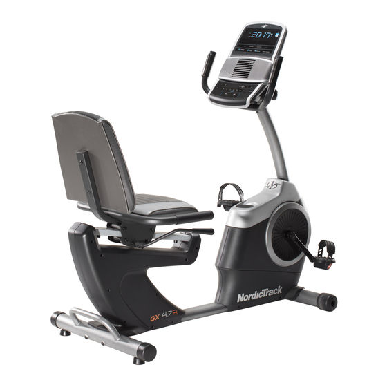
Model No. 21918.0
Serial No.
Write the serial number in the space
above for reference.
Serial Number
Decal
ACTIVATE YOUR
WARRANTY
To register your product and
activate your warranty today,
go to my.nordictrack.com.
CUSTOMER CARE
For service at any time, go to
nordictrackservice.com.
Or call 1-800-TO-BE-FIT
(1-800-862-3348)
Mon.–Fri. 6 a.m.–6 p.m. MT
Sat. 8 a.m.–12 p.m. MT
Please do not contact the store.
CAUTION
Read all precautions and
instructions in this manual before
using this equipment. Keep this
manual for future reference.
USER'S MANUAL
Advertisement
Table of Contents

Related Manuals for NordicTrack GX4.7R


Summary of Contents for NordicTrack GX4.7R
- Page 1 Serial Number Decal ACTIVATE YOUR WARRANTY To register your product and activate your warranty today, go to my.nordictrack.com. CUSTOMER CARE For service at any time, go to nordictrackservice.com. Or call 1-800-TO-BE-FIT (1-800-862-3348) Mon.–Fri. 6 a.m.–6 p.m. MT Sat.
-
Page 2: Table Of Contents
NORDICTRACK and IFIT are registered trademarks of ICON Health & Fitness, Inc. App Store is a trademark of Apple Inc., registered in the U.S. and other countries. Android and Google Play are trademarks of Google LLC. -
Page 3: Important Precautions
IMPORTANT PRECAUTIONS WARNING: To reduce the risk of serious injury, read all important precautions and instructions in this manual and all warnings on the exercise bike before using the exercise bike. ICON assumes no responsibility for personal injury or property damage sustained by or through the use of this product. - Page 4 STANDARD SERVICE PLANS...
-
Page 5: Before You Begin
BEFORE YOU BEGIN Thank you for selecting the new NORDICTRACK reading this manual, please see the front cover of this ® GX 4.7 R exercise bike. Cycling is an effective exercise manual. To help us assist you, note the product model for increasing cardiovascular fitness, building endur- number and serial number before contacting us. -
Page 6: Part Identification Chart
PART IDENTIFICATION CHART Use the drawings below to identify the small parts needed for assembly. The number in parentheses below each drawing is the key number of the part, from the PART LIST near the end of this manual. The number following the key number is the quantity needed for assembly. -
Page 7: Assembly
“R” or “Right.” wrenches. To avoid damaging parts, do not use power tools. • To identify small parts, see page 6. 1. Go to my.nordictrack.com on your computer and register your product. • documents your ownership • activates your warranty •... - Page 8 3. Orient the Front Stabilizer (2) as indicated by the sticker. While a second person lifts the front of the Frame (1), attach the Front Stabilizer (2) to the Frame with two M10 x 80mm Screws (21). 4. Orient the Adjustment Lever (6) as shown. Attach the Adjustment Lever (6) to the Brake Axle (37) with two M6 x 16mm Screws (33), two M6 Split Washers (34), and two M6 Large...
- Page 9 6. Orient the Seat (10) and the Seat Frame (9) as shown. Attach the Seat (10) to the Seat Frame (9) with four M6 x 40mm Screws (27); start all the Screws, and then tighten them. 7. Attach the Seat Frame (9) to the Seat Carriage (7) with four M8 x 40mm Screws (28);...
- Page 10 8. Orient the Backrest (11) as shown. Attach the Backrest (11) to the Backrest Frame (8) with two M6 x 40mm Screws (27). 9. Remove the Accessory Tray (5) from the Left and Right Front Shields (57, 58). Set the Accessory Tray aside.
- Page 11 10. Tip: Avoid pinching the Main Wire (77). Hold the Upright (4) against the Frame (1). Attach the Upright with four M8 x 15mm Screws (24); start all the Screws, and then tighten them. Next, orient the Accessory Tray (5) and the Avoid Console Cover (16) as shown.
- Page 12 12. While a second person holds the Console (15) near the Handlebar (14), connect the wires on the Console to the Main Wire (77) and the Pulse Wire (84). Insert the excess wire into the Handlebar (14). Tip: Avoid pinching the wires. Attach the Console (15) to the Handlebar (14) with two M4 x 16mm Screws (49) in the location shown.
- Page 13 14. Attach the Tablet Holder (87) to the Console (15) with four Tablet Holder Screws (88); start all the Tablet Holder Screws, and then tighten them. 15. Identify the Right Pedal (13). Using an adjustable wrench, firmly tighten the Right Pedal (13) clockwise into the Right Crank Arm (71).
- Page 14 16. After the exercise bike is assembled, inspect it to make sure that it is assembled correctly, that it functions properly, and that all parts are properly tightened. Extra parts may be included. Place a mat under the exercise bike to protect the floor or carpet.
-
Page 15: How To Use The Exercise Bike
HOW TO USE THE EXERCISE BIKE HOW TO PLUG IN THE POWER ADAPTER HOW TO ADJUST THE SEAT IMPORTANT: If the exercise bike has been exposed The seat can be to cold temperatures, allow it to warm to room tem- adjusted forward perature before you plug in the power adapter (A). - Page 16 HOW TO LEVEL THE EXERCISE BIKE HOW TO USE THE TABLET HOLDER If the exercise bike IMPORTANT: The tablet holder (H) is designed for use with most full-size tablets. Do not place rocks slightly on your any other electronic device or object in the tablet floor during use, turn one or both of the holder.
- Page 17 CONSOLE DIAGRAM FEATURES OF THE CONSOLE IMPORTANT: To activate your console and begin using its exclusive features, see assembly step 17 on page 14. The advanced console offers an array of features designed to make your workouts more effective and enjoyable.
- Page 18 HOW TO USE THE MANUAL MODE 4. Follow your progress with the displays. 1. Begin pedaling or press any button on the The display can show the following workout console to turn on the console. information: When you turn on the console, the display will turn Calories (CALS)—When the manual mode and on.
- Page 19 Press the Next Display button repeatedly to view To change the volume the desired workout information in the display. level of the console, press the volume increase and decrease buttons. To pause the console, simply stop pedaling. When the console is paused, the time will flash in the Scan mode—The console also has a scan mode display.
- Page 20 HOW TO USE AN ONBOARD WORKOUT When your pulse is detected, your heart rate will be shown in the display. For the most accurate heart rate reading, hold the contacts for at least 15 1. Begin pedaling or press any button on the seconds.
- Page 21 IMPORTANT: The target speed is intended only HOW TO USE THE SOUND SYSTEM to provide motivation. Your actual pedaling speed may be slower than the target speed. To play music or audio books through the console Make sure to pedal at a speed that is comfort- sound system while you exercise, plug a 3.5 mm male able for you.
- Page 22 HOW TO CONNECT YOUR TABLET TO THE 5. Disconnect your tablet from the console if CONSOLE desired. The console supports BLUETOOTH connections To disconnect your tablet from the console, first to tablets via the iFit–Smart Cardio Equipment app select the disconnect option in the iFit–Smart and to compatible heart rate monitors.
- Page 23 HOW TO CHANGE CONSOLE SETTINGS Total Time—The word TIME will appear in the display. The display will show the total number of 1. Select the settings mode. hours that the exercise bike has been used. If you are using the manual mode or an onboard workout, you must stop pedaling and exit the work- out before you can select the settings mode.
-
Page 24: Fcc Information
FCC INFORMATION This equipment has been tested and found to comply with the limits for a Class B digital device, pursuant to Part 15 of the FCC Rules. These limits are designed to provide reasonable protection against harmful interference in a residential installation. This equipment generates, uses, and can radiate radio frequency energy and, if not installed and used in accordance with the instructions, may cause harmful interference to radio communications. -
Page 25: Maintenance And Troubleshooting
MAINTENANCE AND TROUBLESHOOTING MAINTENANCE HOW TO ADJUST THE REED SWITCH Regular maintenance is important for optimal If the console does not display correct feedback, the performance and to reduce wear. Inspect and properly reed switch should be adjusted. tighten all parts each time the exercise bike is used. Replace any worn parts immediately. -
Page 26: Exercise Guidelines
EXERCISE GUIDELINES Burning Fat—To burn fat effectively, you must exer- WARNING: cise at a low intensity level for a sustained period of Before beginning this time. During the first few minutes of exercise, your or any exercise program, consult your physi- body uses carbohydrate calories for energy. - Page 27 SUGGESTED STRETCHES The correct form for several basic stretches is shown at the right. Move slowly as you stretch; never bounce. 1. Toe Touch Stretch Stand with your knees bent slightly and slowly bend forward from your hips. Allow your back and shoulders to relax as you reach down toward your toes as far as possible.
- Page 28 NOTES...
-
Page 29: Part List
PART LIST Model No. 21918.0 R0818A Key No. Qty. Description Key No. Qty. Description Frame Roller Axle Front Stabilizer Carriage Rail Rear Stabilizer Carriage Rail Bumper Upright M4 x 16mm Screw Accessory Tray Pivot Bracket Inner Bushing Adjustment Lever Pivot Bracket Outer Bushing Seat Carriage M8 x 10mm Screw Backrest Frame... -
Page 30: Exploded Drawing
EXPLODED DRAWING A Model No. 21918.0 R0818A... - Page 31 EXPLODED DRAWING B Model No. 21918.0 R0818A...
-
Page 32: Ordering Replacement Parts
ORDERING REPLACEMENT PARTS To order replacement parts, please see the front cover of this manual. To help us assist you, be prepared to provide the following information when contacting us: • the model number and serial number of the product (see the front cover of this manual) •...