Advertisement
Table of Contents
- 1 Table of Contents
- 2 Warning Decal Placement
- 3 Important Precautions
- 4 Before You Begin
- 5 Part Identification Chart
- 6 Assembly
- 7 How to Use the Exercise Bike
- 8 How to Use the Console
- 9 Maintenance and Troubleshooting
- 10 Exercise Guidelines
- 11 Part List
- 12 Exploded Drawing
- 13 Ordering Replacement Parts
- 14 Recycling Information
- Download this manual
Model No. NTEVEX77020.0
Serial No.
Write the serial number in the space
above for reference.
CUSTOMER SERVICE
UNITED KINGDOM
Call: 0330 123 1045
From Ireland: 053 92 36102
Website: iconsupport.eu
E-mail: csuk@iconeurope.com
Write:
ICON Health & Fitness, Ltd.
Unit 4, Westgate Court
Silkwood Park
OSSETT
WF5 9TT
UNITED KINGDOM
AUSTRALIA
Call: 1800 993 770
E-mail: australiacc@iconfitness.com
Write:
ICON Health & Fitness
PO Box 635
WINSTON HILLS NSW 2153
AUSTRALIA
CAUTION
Read all precautions and
instructions in this manual before
using this equipment. Keep this
manual for future reference.
Serial
Number
Decal
USER'S MANUAL
iconeurope.com
Advertisement
Table of Contents

Related Manuals for NordicTrack GX 4.5 PRO


Summary of Contents for NordicTrack GX 4.5 PRO
- Page 1 Model No. NTEVEX77020.0 Serial No. USER’S MANUAL Write the serial number in the space above for reference. Serial Number Decal CUSTOMER SERVICE UNITED KINGDOM Call: 0330 123 1045 From Ireland: 053 92 36102 Website: iconsupport.eu E-mail: csuk@iconeurope.com Write: ICON Health & Fitness, Ltd. Unit 4, Westgate Court Silkwood Park OSSETT...
-
Page 2: Table Of Contents
Note: The decal(s) may not be shown at actual size. NORDICTRACK and IFIT are registered trademarks of ICON Health & Fitness, Inc. App Store is a trademark of Apple Inc., registered in the U.S. and other countries. Android and Google Play are trademarks of Google LLC. -
Page 3: Important Precautions
IMPORTANT PRECAUTIONS WARNING: To reduce the risk of serious injury, read all important precautions and instructions in this manual and all warnings on your exercise bike before using your exercise bike. ICON assumes no responsibility for personal injury or property damage sustained by or through the use of this product. -
Page 4: Before You Begin
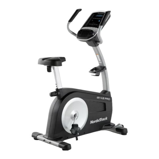
The GX 4.5 PRO exercise bike decal are shown on the front cover of this manual. provides an impressive selection of features designed... -
Page 5: Part Identification Chart
PART IDENTIFICATION CHART Use the drawings below to identify the small parts needed for assembly. The number in parentheses below each drawing is the key number of the part, from the PART LIST near the end of this manual. The number following the key number is the quantity needed for assembly. -
Page 6: Assembly
ASSEMBLY • Assembly requires two persons. • In addition to the included tool(s), assembly requires the following tools: • Place all parts in a cleared area and remove the one Phillips screwdriver packing materials. Do not dispose of the packing materials until you finish all assembly steps. - Page 7 3. Attach the Rear Stabilizer (3) to the Frame (1) with two M10 x 110mm Screws (53). 4. Orient the Upright (4) and the Shield Cover (7) as shown. Slide the Shield Cover upward onto the Upright. Have a second person hold the Upright (4) and the Shield Cover (7) near the front of the Frame (1).
- Page 8 5. Tip: Avoid pinching the wires. Slide the Upright (4) onto the Frame (1). Attach the Upright (4) with four M10 x 15mm Screws (65) and four M10 Washers (31); start all the Screws, and then tighten them. Do not press the Shield Cover (7) into Avoid pinching place yet.
- Page 9 7. Orient the Knob Shield (9) as shown, and press it onto the Shield Cover (7). Then, tighten the Seat Post Knob (27) into the Frame (1). Next, loosen and pull the Seat Post Knob (27), slide the Seat Post (6) upward or downward to the desired position, and then release the Seat Post Knob.
- Page 10 9. Remove the Seat Knob (26) from the Seat Bracket (30) inside the Seat Carriage (24). Next, set the Seat Carriage (24) on the Seat Post (6). Then, insert the Seat Knob (26) upward into the Seat Post, and tighten the Seat Knob into the Seat Bracket (30) inside the Seat Carriage.
- Page 11 12. Have a second person hold the Right Handlebar (5) near the Upright (4). Attach the Right Handlebar (5) to the Upright (4) with two M8 x 16mm Screws (63); start both Screws, and then tighten them. Repeat this step with the Left Handlebar (14). 13.
- Page 12 15. Attach the Accessory Tray (8) to the Upright (4) with two M4 x 18mm Truss Screws (34). 16. Identify the Right Pedal (21). Using an adjust- able wrench, firmly tighten the Right Pedal clockwise into the Right Crank Arm (19). Firmly tighten the Left Pedal (not shown) counterclockwise into the Left Crank Arm (not shown).
- Page 13 17. Plug the Power Adapter (61) into the Power Receptacle (29) on the front of the exercise bike. Note: To plug the Power Adapter (61) into an outlet, see HOW TO PLUG IN THE POWER ADAPTER on page 14. 18. After the exercise bike is assembled, inspect it to make sure that it is assembled correctly and that it functions properly.
-
Page 14: How To Use The Exercise Bike
HOW TO USE THE EXERCISE BIKE HOW TO PLUG IN THE POWER ADAPTER HOW TO ADJUST THE LATERAL POSITION OF THE SEAT IMPORTANT: If the exercise bike has been exposed to cold temperatures, allow it to warm to room tem- To adjust the lateral perature before you plug in the power adapter (A). - Page 15 HOW TO LEVEL THE EXERCISE BIKE THE OPTIONAL TABLET HOLDER If the exercise bike The optional tablet rocks slightly on your holder (G) will hold floor during use, turn your tablet securely one or both of the lev- in place and enable eling feet (F) beneath you to use your tablet the rear stabilizer...
-
Page 16: How To Use The Console
HOW TO USE THE CONSOLE CONSOLE DIAGRAM FEATURES OF THE CONSOLE Each iFit workout automatically changes the resistance of the pedals as an iFit coach guides you through an The advanced console offers an array of features immersive and effective video workout. designed to make your workouts more effective and To use the manual mode, see page 17. - Page 17 HOW TO USE THE MANUAL MODE Calories per Hour (CALS/HR)—The approximate number of calories you are burning per hour. 1. Begin pedaling or press any button on the console to turn on the console. Resistance (RESIST)—The resistance level of the pedals.
- Page 18 To manually advance the scan cycle, press the 5. Wear a compatible heart rate monitor and Multi-scan button repeatedly. measure your heart rate if desired. To turn off the scan mode, press the Next Display You can wear a compatible heart rate monitor to button;...
- Page 19 7. When you are finished exercising, the console HOW TO USE AN IFIT WORKOUT will turn off automatically. The console offers access to a large and varied library If the pedals are not moved for a few seconds, the of iFit workouts when you download the iFit app to your console will pause and the time will flash in the smart device and connect it to the console.
- Page 20 4. Select an iFit workout. To pause the workout, simply touch the screen or stop pedaling. To continue the workout, simply In the iFit app, touch the buttons at the bottom of resume pedaling. the screen to select either the main menu (Home button) or the workout library (Browse button).
- Page 21 HOW TO CONNECT YOUR HEART RATE MONITOR HOW TO CHANGE CONSOLE SETTINGS TO THE CONSOLE 1. Select the settings mode. The console is compatible with all Bluetooth Smart heart rate monitors. If you are using the manual mode, you must stop pedaling and exit the workout before you can select To connect your Bluetooth Smart heart rate monitor to the settings mode.
- Page 22 Display Test—This screen is intended to be used Contrast Level—The currently selected contrast by service technicians to identify whether the level will appear in the display. Press the display is working correctly. Resistance increase and decrease buttons to adjust the contrast level. Button Test—This screen is intended to be used by service technicians to identify whether a certain button is working correctly.
-
Page 23: Maintenance And Troubleshooting
MAINTENANCE AND TROUBLESHOOTING MAINTENANCE If the console does not boot up properly, or if the con- Regular maintenance is important for optimal sole freezes and does not performance and to reduce wear. Inspect and properly respond, reset the console tighten all parts each time the exercise bike is used. to the factory default set- Replace any worn parts immediately. - Page 24 HOW TO ADJUST THE REED SWITCH See the lower drawing at the left. Carefully pull the tops of the Shields (10, 11) apart and locate the Reed If the console does not display correct feedback, the Switch (57). Rotate the Left Crank Arm (20) until a reed switch should be adjusted.
-
Page 25: Exercise Guidelines
EXERCISE GUIDELINES Aerobic Exercise—If your goal is to strengthen your WARNING: cardiovascular system, you must perform aerobic Before beginning this exercise, which is activity that requires large amounts or any exercise program, consult your physi- of oxygen for prolonged periods of time. For aerobic cian. -
Page 26: Part List
PART LIST Model No. NTEVEX77020.0 R1020A Key No. Qty. Description Key No. Qty. Description Frame M8 x 28mm Hex Screw Front Stabilizer Leveling Foot Rear Stabilizer Handgrip Upright Pulley Right Handlebar Crank Seat Post Crank Bearing Shield Cover Snap Ring Accessory Tray Eddy Mechanism Knob Shield... -
Page 27: Exploded Drawing
EXPLODED DRAWING Model No. NTEVEX77020.0 R1020A... -
Page 28: Ordering Replacement Parts
ORDERING REPLACEMENT PARTS To order replacement parts, please see the front cover of this manual. To help us assist you, be prepared to provide the following information when contacting us: • the model number and serial number of the product (see the front cover of this manual) •...