Table of Contents
Advertisement
P/N 126861-01 Rev.A 02/2014
P126861-01
INSTALLER: Leave this manual with the appliance.
CONSUMER: Retain this manual for future reference.
This appliance may be installed in an aftermarket permanently located, manufactured (mobile) home, where not
prohibited by local codes. This appliance is only for use with the type of gas indicated on the rating plate. This
appliance is not convertible for use with other gases.
This is an unvented gas-fired heater. It uses air (oxygen) from the room in which it is installed. Provisions
for adequate combustion and ventilation air must be provided. Refer to Air for Combustion and Ventilation
section on page 6 of this manual.
WARNING: If the information in these instructions is not followed exactly, a fire or explosion may result
causing property damage, personal injury or loss of life.
— Do not store or use gasoline or other flammable vapors and liquids in the vicinity of this or any other
appliance.
— WHAT TO DO IF YOU SMELL GAS:
• Do not try to light any appliance.
• Do not touch any electrical switch; do not use any phone in your building.
• Immediately call your gas supplier from a neighbor's phone. Follow the gas supplier's instructions.
• If you cannot reach your gas supplier, call the fire department.
— Installation and service must be performed by a qualified installer, service agency or the gas supplier.
Installation and Operation Instructions
Superior™ Unvented (Vent-Free) Gas Fireplace
Models
VRL4543ZMN
VRL4543ZMP
Advertisement
Table of Contents

Related Manuals for Superior Fireplaces VRL4543ZMN


Summary of Contents for Superior Fireplaces VRL4543ZMN
- Page 1 Installation and Operation Instructions Superior™ Unvented (Vent-Free) Gas Fireplace P/N 126861-01 Rev.A 02/2014 Models VRL4543ZMN VRL4543ZMP P126861-01 INSTALLER: Leave this manual with the appliance. CONSUMER: Retain this manual for future reference. This appliance may be installed in an aftermarket permanently located, manufactured (mobile) home, where not prohibited by local codes.
-
Page 2: Table Of Contents
TABLE OF CONTENTS Safety ..............2 Wiring Diagram ..........26 Local Codes............4 Troubleshooting ..........27 Product identification ........... 5 Specifications ............ 30 Product Features ..........5 Replacement Parts ..........30 Air for Combustion and Ventilation ...... 6 Service Hints ............. 30 Installation ............ - Page 3 SAFETY Continued Do not place clothing or other DANGER: Carbon monoxide flammable material on or near poisoning may lead to death! the appliance. Never place any objects on the heater. Carbon Monoxide Poisoning: Early signs of carbon monoxide poisoning resemble the Fireplace become very hot when flu, with headaches, dizziness or nausea.
-
Page 4: Local Codes
SAFETY Continued 6. Do not add extra logs or ornaments such 11. Do not run fireplace as pine cones, vermiculite, or rock wool. • where flammable liquids or vapors are Using these added items can cause soot- used or stored. ing. -
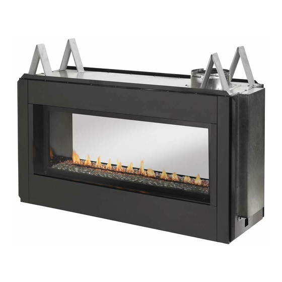
Page 5: Product Identification
PRODUCT IDENTIFICATION Spacers Left Side Right Side Nailing Flange Front Pebble Pan Access Door Figure 1 - Vent Free Linear Fireplace PRODUCT FEATURES OPERATION SAFETY DEVICE This vent-free fireplace is clean burning. It This fireplace has a pilot with an Oxygen Deple- requires no outside venting. -
Page 6: Air For Combustion And Ventilation
AIR FOR COMBUSTION AND VENTILATION Unusually Tight Construction WARNING: This heater shall The air that leaks around doors and windows not be installed in a room or may provide enough fresh air for combustion and ventilation. However, in buildings of un- space unless the required vol- usually tight construction, you must provide ume of indoor combustion air... - Page 7 AIR FOR COMBUSTION AND VENTILATION Continued DETERMINING FRESH-AIR FLOW 4. Compare the maximum Btu/Hr the space can support with the actual amount of Btu/Hr used. FOR FIREPLACE LOCATION _______ Btu/Hr (maximum the space can Determining if You Have a Confined or support) Unconfined Space _______ Btu/Hr (actual amount of Btu/Hr...
- Page 8 AIR FOR COMBUSTION AND VENTILATION Continued VENTILATION AIR Ventilation Air From Outdoors Provide extra fresh air by using ventilation Ventilation Air From Inside Building grills or ducts. You must provide two perma- This fresh air would come from an adjoining nent openings: one within 12"...
-
Page 9: Installation
INSTALLATION Continued INSTALLATION CLEARANCES CAUTION: This fireplace cre- WARNING: Maintain the ates warm air currents. These minimum clearances. If you can, currents move heat to wall sur- provide greater clearances from faces next to fireplace. Installing floor, ceiling and adjoining wall. fireplace next to vinyl or cloth wall coverings or operating Carefully follow the instructions below. - Page 10 INSTALLATION Continued 17.50" Concrete Board 38" 53.25" Figure 6 - Installing Concrete Board Mantel Figure 4 - Framing Clearances for One from Sided Application Mantel Top of Ref. Depth Ref. Opening Note: All vertical 15.25" 12" 24" measurements are 9" 21"...
- Page 11 INSTALLATION Continued Figure 8 - VRL4543 Series Dimensions www.SuperiorFireplaces.US.com 126861-01A...
- Page 12 INSTALLATION Continued Sheet Mantel Clearances for Built-In Metal Installation Screws If placing mantel above built-in fireplace, you must meet minimum clearance between man- tel shelf and top of fireplace opening. NOTICE: If your installation does not meet the minimum clear- Electrical Electrical ances shown, you must do one...
- Page 13 INSTALLATION Continued External Propane/LP WARNING: Never connect Regulator Supply Tank natural gas fireplace to private (non-utility) gas wells. This gas is commonly known as wellhead gas. Installation Items Needed Vent Before installing fireplace, make sure you Pointing have the items listed below. Down •...
-
Page 14: Connecting Fireplace To Gas Supply
INSTALLATION Continued Equipment Shutoff 1. Route flexible gas line (provided by in- Valve With 1/8" NPT staller) from equipment shutoff valve to Tap* fireplace. Route flexible gas supply line Natural Gas through one of the access holes on side From Gas Meter of fireplace. - Page 15 INSTALLATION Continued PRESSURE TESTING GAS SUPPLY Equipment Shutoff Valve PIPING SYSTEM Propane/ Test Pressures In Excess Of 1/2 PSIG LP Supply (3.5 kPa) Tank 1. Disconnect fireplace with its appliance main gas valve (control valve) and equip- ment shutoff valve from gas supply piping system.
- Page 16 INSTALLATION Continued FINISHING FIREPLACE FOR UPGRADING VRL4543 TO SEE-THRU INSTALLATION APPLICATION VRL4543 series fireplace come with the rear Removing Rear Panel panel semi-installed. If you will be using the 1. In the rear of the fireplace, locate screws fireplace for a one sided regular application, at top of rear panel and remove as shown you will need to finish the installation of the in Figure 18.
- Page 17 INSTALLATION Continued Removing False Door Installing Access Door Retaining 1. In the rear of the fireplace, Unlock 3 door Brackets latches on top of firebox using your 1. Screw access door retaining brackets into fingers or the latch opener provided. the inner side face using 2 screws on both the left and right side as shown in Figure 2.
- Page 18 INSTALLATION Continued Installing Access Door 1. Place access door into retangular opening in front of the glass door with the slanted side facing forward. The slanted surface will slide underneath the flange of the bottom face Insert tabs on side of access door into slots on retaining brackets (See Figure 24).
- Page 19 INSTALLATION Continued GLASS PEBBLE INSTALLATION WARNING: Do not change or substitute glass pebbles provided with this fireplace. If replacing, use only replacement glass pebbles. See Replacement Parts page 30. Remote Clear glass pebbles are included with your Receiver Backup fireplace. Battery 1.
-
Page 20: Operation
OPERATION This appliance requires 120V electricity for FOR YOUR SAFETY normal operation. Control module should be READ BEFORE LIGHTING plugged into electrical outlet located under- neath firebox bottom. Back up battery supply WARNING: If you do not fol- is available for power outages. low these instructions exactly, 1. - Page 21 OPERATION Continued Low Battery - Remote Receiver CAUTION: Do not try to ad- When batteries in receiver are low, no "beep" just heating levels by using the will be admitted from the receiver when ON/ equipment shutoff valve. OFF button is pressed. This is an alert for a low battery condition for the receiver.
- Page 22 OPERATION Continued ROOM THERMOSTAT The remote control can operate as a room thermostat. The thermostat can be set to a desired temperature to control the comfort Display level in the room. To activate, press THERMOSTAT button on re- mote control (see Figure 36). The word ON will appear to the right of temperature bulb graphic on display (see Figure 36).
- Page 23 OPERATION Continued CHILD SAFETY LOCK-OUT PROGRAMMING REMOTE CONTROL TO This function lets you deactivate the remote RECEIVER control buttons. It is active when the lock icon If your remote ever needs to be replaced you is lit on the display. will not need to replace the receiver.
-
Page 24: Cleaning And Maintenance
CLEANING AND MAINTENANCE 4. Check the orifice located at the end of WARNING: Turn off fireplace the burner tube again. Remove any large and let cool before cleaning. particles of dust, dirt, lint or pet hair with a soft cloth or vacuum cleaner nozzle. CAUTION: You must keep 5. -
Page 25: Inspecting Burners
INSPECTING BURNERS BURNER PRIMARY AIR HOLES Check pilot flame pattern and burner flame patterns often. Air is drawn into the burner through the holes in the fitting at the burner entrance. These PILOT FLAME PATTERN holes may become blocked with dust or lint. Figure 44 shows a correct pilot flame pattern. -
Page 26: Wiring Diagram
WIRING DIAGRAM Yellow Green Orange White Blue Blue White Green Black Remote Receiver www.SuperiorFireplaces.US.com 126861-01A... -
Page 27: Troubleshooting
TROUBLESHOOTING WARNING: Turn off heater and let cool before servicing. Only a qualified service person should service and repair heater. CAUTION: Never use a wire, needle or similar object to clean ODS/pilot. This can damage ODS/pilot unit. Note: All troubleshooting items are listed in order of operation. OBSERVED PROBLEM POSSIBLE CAUSE REMEDY... - Page 28 TROUBLESHOOTING Continued OBSERVED PROBLEM POSSIBLE CAUSE REMEDY Slight smoke or odor during 1. Not enough air 1. Check burner for dirt and initial operation debris. If found, clean burner (see Cleaning and Maintenance, page 24) Heater produces a whistling 1. Not enough combustion/ 1.
- Page 29 TROUBLESHOOTING Continued WARNING: If you smell gas • Shut off gas supply. • Do not try to light any appliance. • Do not touch any electrical switch; do not use any phone in your building. • Immediately call your gas supplier from a neighbor’s phone. Fol- low the gas supplier’s instructions.
-
Page 30: Specifications
SPECIFICATIONS VRL4543ZMN VRL4543ZMP • Rating (Variable): 25/39,000 Btu/Hr • Rating (Variable): 29/37,000 Btu/Hr • Gas Type: Natural Gas • Gas Type: Propane/LP Gas • Ignition: Piezo • Ignition: Piezo • Pressure Manifold Setting: 3.5" W.C. • Pressure Manifold Setting: 10.5" W.C. -
Page 31: Accessories
ACCESSORIES NOTICE: All accessories may DECORATIVE FACE TRIM not be available for all fireplace DFT43B - Black models. DFT43AS - Aged Silver DFT43AC - Aged Copper Purchase these accessories from your local SEE-THRU DOOR KIT dealer. If they can not supply these accessories call INNOVATIVE HEARTH PRODUCTS at LVSTI 1-800-655-2008 for information. -
Page 32: Parts
PARTS MODELS VRL4543ZMN & VRL4543ZMP www.SuperiorFireplaces.US.com 126861-01A... - Page 33 PARTS This list contains replaceable parts used in your fireplace. When ordering parts, follow the instructions listed under Replacement Parts on page 30 of this manual. PART NO. DESCRIPTION VRL4543ZMN VRL4543ZMP QTY. 126487-01 Shield, Draft ODS Pilot VF • •...
- Page 34 PARTS MODELS VRL4543ZMN & VRL4543ZMP www.SuperiorFireplaces.US.com 126861-01A...
-
Page 35: Burner Assembly
BURNER ASSEMBLY This list contains replaceable parts used in your fireplace. When ordering parts, follow the instructions listed under Replacement Parts on page 30 of this manual. NO. PART NO. DESCRIPTION VRL4543ZMN VRL4543ZMP QTY. 125847-01 Top Spacer • • 125757-02 Top Nailing Flange •... -
Page 36: Warranty
THE WARRANTY Innovative Hearth Products ("IHP") 20 Year Limited Warranty warrants your Superior™ Brand gas fireplace, Stove or Insert ("Product") to be free from defects in materials and workmanship at the time of manufacture. The Product body and firebox carry the 20 Year Limited Warranty. Ceramic glass carries the 20 Year Limited Warranty against thermal breakage only. - Page 37 WARRANTY KEEP THIS WARRANTY www.SuperiorFireplaces.US.com 126861-01A...
- Page 38 1508 Elm Hill Pike, Suite 108 Nashville, TN 37210 126861-01 1-800-655-2008 Rev. A www.IHP.US.com 02/14 P126861-01...