Xerox Phaser 4500 Service Manual
Hide thumbs
Also See for Phaser 4500:
- Service manual (537 pages) ,
- Reference manual (204 pages) ,
- Quick reference manual (11 pages)
Table of Contents
Advertisement
Quick Links
Advertisement
Table of Contents
Troubleshooting

Related Manuals for Xerox Phaser 4500


Summary of Contents for Xerox Phaser 4500
- Page 1 Service Manual 701P45760 Phaser 4500/4510 ® Laser Printers...
- Page 3 Service Manual 701P45760 Phaser 4500/4510 Laser Printers Warning The following servicing instructions are for use by qualified service personnel only. To avoid personal injury, do not perform any servicing other than that contained in the operating instructions, unless you are...
- Page 4 Xerox technical training materials and service manuals are intended for use by authorized Xerox service technicians and service partners only and are not for resale. These materials may not be distributed, copied or otherwise reproduced without prior written consent from Xerox Corporation.
-
Page 5: Table Of Contents
Overview of the Phaser 4500/4510 Laser Printer........ - Page 6 No Recognition of Stacker ............. . 3-75 Phaser 4500/4510 Service Manual...
- Page 7 Offset Sensor (On Stacker PWBA)............4-61 Phaser 4500/4510 Laser Printer Service Manual...
- Page 8 Resetting All Printer Default Settings (PostScript NVRAM) ........6-13 Phaser 4500/4510 Service Manual...
- Page 9 Duplex Unit Opening Cover ............. 8-48 Phaser 4500/4510 Laser Printer Service Manual...
- Page 10 Duplex Unit Switch ..............8-110 viii Phaser 4500/4510 Service Manual...
- Page 11 Xerox Supplies and Accessories ........
- Page 12 Phaser 4500 Menu Map........
-
Page 13: Service Terms
NOT an option to the product. Throughout this manual any pieces of information that pertain to just the Phaser 4500 are indicated with P4500, and those that pertain to just the Phaser 4510 are indicated with P4510. Those that apply to both models do not have either label. -
Page 14: Product Terms
The surface is hot while the printer is running. After turning off the power, wait 30 minutes. 30 min. Use caution (or draws attention to a particular component). Refer to the manual(s) for information. Do not touch the item. Phaser 4500/4510 Service Manual... -
Page 15: Power Safety Precautions
254 volts RMS between the supply conductors or between either supply conductor and ground. Use only the specified power cord. This manual assumes that the reader is a Xerox-certified service technician. Plug the three-wire power cord (with grounding prong) into a grounded AC outlet only. -
Page 16: Electrostatic Discharge (Esd) Precautions
Handle ICs and EPROMs carefully to avoid bending pins. Pay attention to the direction of parts when mounting or inserting them on Printed Circuit Boards (PCB’s). Phaser 4500/4510 Service Manual... -
Page 17: Service Safety Summary
CLASS 1 LASER PRODUCT The Phaser 4500/4510 Laser Printer is certified to comply with Laser Product Performance Standards set by the U.S. Department of Health and Human Services as a Class 1 Laser Product. This means that this is a class of laser product that does not emit hazardous laser radiation;... -
Page 18: Servicing Electrical Components
This printer uses heat to fuse the toner image to media. The fuser assembly is VERY HOT. Turn the printer power off and wait at least 5 minutes for the Fuser to cool before you attempt to service the fuser assembly or adjacent components. Phaser 4500/4510 Service Manual... -
Page 19: Regulatory Specifications
United States (Federal Communications Commision The equipment described in this manual generates and uses radio frequency energy. If it is not installed properly in strict accordance with Xerox instructions, it may cause interference with radio and television reception or may not function properly due to interference from another device. However, there is no guarantee that interference will not occur in a particular installation. - Page 20 European Union The CE mark applied to this product symbolizes Xerox’s declaration of conformity with the following applicable Directives of the European Union as of the dates indicated: January 1, 1995: Low Voltage Directive 73/23/EEC as amended by 98/68/ January 1, 1996: Electromagnetic Compatibility Directive 89/336/EEC March 9, 1999: Radio &...
-
Page 21: General Information
General Information In this chapter... Printer Introduction and Overview Printer Configurations Parts of the Printer Control Panel Image Processor Board (Phaser 4500) Image Processor Board (Phaser 4510) Consumables and Routine Maintenance Items Printer Specifications Chapter... -
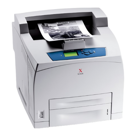
Page 22: Printer Introduction And Overview
General Information Printer Introduction and Overview The Xerox Phaser 4500/4510 Laser Printer Service Manual is the primary document used for repairing, maintaining, and troubleshooting the printer. To ensure complete understanding of this product, participation in Xerox Phaser 4500/4510 Service Training is strongly recommended. To service this product, Xerox certification for this product is required. -
Page 23: Printer Configurations
Hard drive Optional Optional Optional Standard Job collation Optional Optional Optional Standard (Requires a hard drive) Proof Print, Secure Print, Saved Optional Optional Optional Standard Jobs (Requires a hard drive) 500-sheet stacker Optional Optional Optional Standard Phaser 4500/4510 Service Manual... -
Page 24: Parts Of The Printer
Items 1 - 4 are mounted on the image 5. Power receptacle processor board. 6. Optional duplex unit 1. Ethernet 10/100 Base-T connector 7. Rear cover 2. Configuration card 8. Stacker rear cover 3. USB connector 9. Stacker extension 4. Parallel cable connector Phaser 4500/4510 Service Manual... -
Page 25: Control Panel
LED State Printer State Green Ready to Print or in Power Saver mode Flashing Yellow Warning (but can still print) Flashing Green In Standby mode or busy (receiving data, processing data, printing) Flashing Red Error; cannot print Phaser 4500/4510 Service Manual... - Page 26 Control Panel Shortcuts Mode Buttons Pressed at Power On Skip execution of POST diagnostics Print Service Diagnostics Map Information Reset PostScript NVRAM Back + OK Password Bypass Up Arrow + Down Arrow Enter Service Diagnostics Back + Information Phaser 4500/4510 Service Manual...
-
Page 27: Image Processor Board (Phaser 4500)
General Information Image Processor Board (Phaser 4500) When installing a new image processor board in the printer, you must transfer the following parts from the old board: Memory DIMMs Hard drive (if installed) NVRAM Configuration card s4500-251 1. Memory (RAM) DIMM 1 and DIMM 2 6. -
Page 28: Image Processor Board (Phaser 4510)
Flash memory (if installed) s4510-251 1. Memory (RAM) DIMM 1 and DIMM 2 6. Parallel connector 2. Flash memory (optional) 7. Ethernet connector 3. Hard drive (optional) 8. USB connector 4. NVRAM 9. Health LED 5. Configuration Card Phaser 4500/4510 Service Manual... -
Page 29: Consumables And Routine Maintenance Items
General Information Consumables and Routine Maintenance Items Print Cartridge Transfer Roller Feed Rollers 3 per Paper Tray s4510-267 Fuser s4510-268 Phaser 4500/4510 Service Manual... -
Page 30: Supply Life Counters
Print life ratings are based on 5% coverage and an average job length of 4 pages. Supply Print Life (Number of Images) Consumables 10,000 Print cartridge, standard- capacity 19,000 Print cartridge, high-capacity Routine Maintenance Items Maintenance kit (consists of 200,000 fuser, transfer roller, and 12 feed rollers) 1-10 Phaser 4500/4510 Service Manual... -
Page 31: Printer Specifications
1.9 kg (4.2 lbs.) Stacker Dimensions Value Height 226 mm (8.9 in.) Width 418 mm (16.4 in.) Depth 312 mm (12.3 in.) Depth with stacker tray extended 382 mm (15.1 in.) Weight 2.6 kg (5.7 lbs.) Phaser 4500/4510 Service Manual 1-11... -
Page 32: Functional Specifications
First Print-Out Letter Simplex 24.9 24.9 24.9 25.2 from sleep mode Duplex 28.1 28.1 28.1 28.3 (in seconds); Simplex 24.9 24.9 24.9 25.2 Short Edge Feed Duplex 28.2 28.2 28.2 28.4 Warm-Up Time 17 seconds 1-12 Phaser 4500/4510 Service Manual... -
Page 33: Electrical Specifications
Engine only With all options Idle P4500: 4.00 B — P4510: 5.00 B — Printing P4500: 6.62 B 7.30 B P4510: 6.95 B 7.50 B * Air transportation in pressurized cargo space qualified printer NERGY Phaser 4500/4510 Service Manual 1-13... -
Page 34: Media And Tray Specifications
P4510: 64-216 g/m (17.1-58 lb.) Types and Greeting Cards 190 g/m (70 lb. Cover) Weights Index Card Stock 60-216 g/m (33-120 lb.) Tag Card Stock 60-216 g/m (37-133 lb.) Cover Stock 60-216 g/m (22-80 lb.) 1-14 Phaser 4500/4510 Service Manual... -
Page 35: Memory Requirements
General Information Memory Requirements Phaser 4500 Characteristic Specification Minimum 64 MB – The Phaser 4500 B configuration reports 48 MB required Maximum 256 MB – accepts modules of 64 or 128 MB in combinations supported to a total of 256 MB... - Page 36 General Information 1-16 Phaser 4500/4510 Service Manual...
-
Page 37: Theory Of Operation
Theory of Operation In this chapter... Overview of the Phaser 4500/4510 Laser Printer Paper Path of the Printer Sensors Major Assemblies and Functions Printer Options Chapter... -
Page 38: Overview Of The Phaser 4500/4510 Laser Printer
Overview of the Phaser 4500/4510 Laser Printer Summary of the Printing Process The Phaser 4500/4510 print process consists of the following steps: Charge – The print cartridge contains a bias charge roller that uniformly distributes a negative electrical charge over the photoconductive drum surface. - Page 39 Fuser Assembly 8. Cleaning Cleaning 1. Charging 7. Fusing Blade 2. Exposure 6. Discharge Drum Detack Saw Paper Laser Beam Transfer Roller Transport Charge Metering Blade 5. Transfer 3. Development Magnetic Roller Print Cartridge Paper s4500-008 Phaser 4500/4510 Service Manual...
-
Page 40: Paper Path Of The Printer
Heat Roller Pressure Roller Fuser Assembly Lower Stacker Roller Exit Roller Exit Pinch Roller Pinch Roller 500-sheet Exit Assembly Upper Stacker Roller Stacker Pinch Roller Optional Stacker Duplex Roller Pinch Roller Print Exit Optional Duplex Unit s4500-017 Phaser 4500/4510 Service Manual... -
Page 41: Layout Of Paper Transport Path
2. Exit pinch roller 9. Metal registration roller 3. Fuser assembly 10.Feed roller assemblies 4. Pressure roller 11.Retard roller assemblies 5. Heat roller 12.Nudger roller assemblies 6. Drum 13.Print cartridge 7. Transfer roller assembly 14.Laser assembly Phaser 4500/4510 Service Manual... - Page 42 2. Lower stacker roller 9. Turn pinch rollers 3. Upper stacker roller 10.Turn roller assemblies 4. Upper stacker pinch roller 11.Feed roller assemblies 5. Exit roller 12.Retard roller assemblies 6. Exit pinch roller 13.Nudger roller assemblies 7. Duplex rollers Phaser 4500/4510 Service Manual...
-
Page 43: Sensors
Mechanically Detects no paper condition Page 2-16 actuated photo in all trays. sensor Paper size Microswitch bank Detects the presence of a Page 2-16 switches tray and the paper size Page 2-41 setting of the tray. Phaser 4500/4510 Service Manual... - Page 44 Stacker rear Microswitch Signals the HVPS/engine Page 2-38 cover switch logic board that the stacker rear cover is open. Stacker sensor Mechanically Senses the presence of Page 2-38 actuated photo paper in the stacker. sensor Phaser 4500/4510 Service Manual...
- Page 45 Optional feeder Microswitch bank Detects the presence of a Page 2-41 paper size switch tray and the paper size assembly setting of the tray. CRUM antenna Inductive magnetic Communicates with the print code reader cartridge CRUM. Phaser 4500/4510 Service Manual...
- Page 46 10.Tray 3 no paper sensor 4. Stacker sensor 11.Tray 3 low paper sensor 5. Stacker full 12.Tray 4 no paper sensor 6. Duplex unit sensor 13.Tray 4 low paper sensor 7. Tray 1 no paper sensor 2-10 Phaser 4500/4510 Service Manual...
-
Page 47: Major Assemblies And Functions
Theory of Operation Major Assemblies and Functions The functions of the main components of the Phaser 4500/4510 printer are described in the following sections: Paper tray Paper feeder Print cartridge Transfer roller assembly Laser assembly Fuser 500-sheet paper exit Drive... - Page 48 Bottom lock lever and gear stopper These are at the rear of the tray (i.e., the front end in the direction of travel of paper). How these components work is explained in “Paper Lift Mechanism” on page 2-14. 2-12 Phaser 4500/4510 Service Manual...
- Page 49 The links, when in contact with the paper size switches in the left tray guide, turn the switches on or off in combinations that correspond to the paper size. Phaser 4500/4510 Service Manual 2-13...
- Page 50 A5 SEF Paper Lift Mechanism The Phaser 4500/4510 printer paper trays utilize a unique mechanical paper lift mechanism that eliminates the need for paper lift motors. The mechanism consists of a spring-loaded bottom plate assembly that lifts the paper stack upward to the paper feeder assembly.
-
Page 51: Paper Feeder
550-sheet feeders, which includes tray 2 and if installed, trays 3 and 4. Low paper sensor This photo sensor remains in an OFF state until the paper level in the tray drops sufficiently to move the low paper actuator flag out of the sensor. Phaser 4500/4510 Service Manual 2-15... - Page 52 7. Metal registration roller 2. Feed clutch assembly 8. No paper sensor 3. Registration clutch 9. No paper actuator 4. Rubber registration roller 10.Low paper sensor 5. Feed roller 11.Low paper actuator 6. Registration sensor 12.Nudger roller 2-16 Phaser 4500/4510 Service Manual...
-
Page 53: Control Of Paper Size
The switches in the paper size switch assembly are denoted by “SW1”, “SW2”, “SW3”, and “SW4”, respectively, from the front side. Paper Size Switch Assembly Paper size No cassette Executive SEF B5(JIS) SEF A5 SEF Legal14”SEF Letter SEF A4 SEF Legal13”SEF Phaser 4500/4510 Service Manual 2-17... -
Page 54: Xerographics
Cleaning blade The cleaning blade scrapes off toner remaining on the drum surface after the transfer step. s4500-010 1. Print cartridge 2. Transfer roller 2-18 Phaser 4500/4510 Service Manual... - Page 55 The resolution in the process direction (from top to bottom) is determined by the number of the scan beams and the rotational speed of the print drum. Conceptual Diagram of Image Creation by Scanning Paper Path 600 Dots/Inch 600 Scans/Inch s4500-011 Phaser 4500/4510 Service Manual 2-19...
- Page 56 Thus, the image is transferred from the surface of the drum to the surface of the paper. The detack saw, located on the transfer roller assembly, helps to separate the paper from the drum surface. 2-20 Phaser 4500/4510 Service Manual...
-
Page 57: Fuser
This sensor detects the arrival of the paper at a detection point in the exit area positioned behind the fuser. This sensor also detects the discharge of the paper from this point. When the sensor receives light (i.e., paper is present), the signal /EXIT is low. Phaser 4500/4510 Service Manual 2-21... - Page 58 Theory of Operation s4500-023 1. Exit motor assembly 5. Pressure roller 2. Exit sensor 6. Heat roller 3. Actuator 7. Thermostats (P4510 uses only one) 4. Temperature sensors 2-22 Phaser 4500/4510 Service Manual...
-
Page 59: Fuser Control
The running temperature and print speed depend on the media type selected for printing. The Phaser 4500 uses four temperature settings while the Phaser 4510 uses six. Print speed slows down for heavy media such as card stock or envelopes, and specialty media such as transparencies. - Page 60 The fuser temperature does not remain at a single, constant value, but varies within a temperature range. There are several ranges, which are summarized in the table. Except for Standby, the setting is determined by the media type selection. Phaser 4500 Fuser Cycling Temperatures Temperature Setting Standby Lamp ON 180°...
- Page 61 High trouble temperature – The fuser temperature rises to the high trouble temperature (approximately current control temperature, plus approximately 35° C). STS circuit open STS failure – The heat rod remains on for at least 10 seconds after warm- up has completed. Phaser 4500/4510 Service Manual 2-25...
- Page 62 Cover open — top, rear, duplex unit, stacker Laser assembly (ROS) abnormality (U2) CPU or NVRAM abnormality (U6) Main motor assembly abnormality (U1) Fan abnormality (U5) Fuser Pause command issued Xerographics failure Duplex unit failure Stacker failure Option tray unit failure 2-26 Phaser 4500/4510 Service Manual...
-
Page 63: Paper Exit Assembly
The gate blocks the normal paper output path and switches the output direction to the stacker output tray. s4500-024 1. Output tray full sensor 3. Stacker exit gate 2. Exit roller 4. Exit motor assembly Phaser 4500/4510 Service Manual 2-27... -
Page 64: Drive
3, and drive to the print cartridge drum is connected or disconnected. s4500-025 s4500-025 1. Main motor 3. Gear assembly housing 2. Gear assembly plate 4. Link lever 2-28 Phaser 4500/4510 Service Manual... -
Page 65: Electrical
HVPS/engine logic board and main motor when the top cover is open. This switch operates in series with the rear cover switch. See “Schematic Diagram of Phaser 4500 Power Distribution and Interlocks” on page 2-31, or “Schematic Diagram of Phaser 4510 Power Distribution and Interlocks” on page 2-32. - Page 66 3. Rear cover switch 9. Image processor board 4. Laser interlock (P4500 only) 10.HVPS/engine logic board 5. Top cover switch (P4500 only) 11.Sub fan 6. Main fan 12.DC-DC converter (separate board in P4500; integrated into LVPS in P4510) 2-30 Phaser 4500/4510 Service Manual...
- Page 67 Heater Rod(650W) Motor LVPS Heater Control Fuse Low Voltage Generation Power 24VDC Switch Supply AC N AC L Fuse 5VDC Supply Inlet Fuse 3.3VDC Supply s4500-027 Schematic Diagram of Phaser 4500 Power Distribution and Interlocks Phaser 4500/4510 Service Manual 2-31...
- Page 68 Heater Control Fuse Low Voltage Generation 3.3VDC DC-DC Power 24VDC Converter 24VDC Switch Supply AC N Fuse AC L 5VDC Supply Inlet Fuse 3.3VDC Supply s4510-027 Schematic Diagram of Phaser 4510 Power Distribution and Interlocks 2-32 Phaser 4500/4510 Service Manual...
-
Page 69: Printer Options
The duplex unit used on the Phaser 4510 differs from the one used on the Phaser 4500. While the two units function exactly the same, they use different motors due to the difference in speed, and they are shaped differently due to the change in the location of the cooling fan. - Page 70 HVPS/engine logic board and information from sensors and switches, and controls paper transport through the duplex unit. Duplex unit motor This motor drives the three duplex rollers, which transport the paper through the duplex unit. 2-34 Phaser 4500/4510 Service Manual...
- Page 71 Theory of Operation Phaser 4500 and 4510 Duplex Units P4500 s4500-030 P4510 s4510-030 1. Duplex unit rollers 4. Duplex unit PWBA 2. Duplex unit sensor 5. Duplex unit switch 3. Duplex unit fan 6. Duplex unit motor Phaser 4500/4510 Service Manual...
-
Page 72: Stacker
Cam Gear Gear 45 Gear 45 Gear 19 Gear 19 Lower OCT Roller Upper OCT Roller s4500-031 Gear Layout s4500-032 1. Gear 45 4. Stacker motor assembly 2. Gear 19 5. Gear 19 3. Gear 19/37 2-36 Phaser 4500/4510 Service Manual... - Page 73 Lower stacker roller into the stacker paper output tray. Offset chute assembly This assembly is driven by the offset motor assembly and Cam gear to move right and left during paper output to offset the output of the printer. Phaser 4500/4510 Service Manual 2-37...
- Page 74 7. Offset motor assembly 2. Upper stacker roller 8. Gate solenoid assembly 3. Rear cover switch 9. Offset chute assembly 4. Full Stack Sensor 10.Stacker sensor 5. Offset Sensor 11.Lower stacker roller 6. Stacker PWBA 2-38 Phaser 4500/4510 Service Manual...
- Page 75 1. Optional feeder gear 6 5. Feeder motor 2. Turn roller clutch 6. Optional feeder gear 2 3. Feed clutch 7. Optional feeder gear 3 4. Optional feeder gear 4 8. Optional feeder gear 5 Phaser 4500/4510 Service Manual 2-39...
-
Page 76: Optional 550-Sheet Feeder
550-sheet feeder PWBA A CPU installed in the 550-sheet feeder PWBA receives instructions from the HVPS/engine logic board and from sensors and switches; the CPU controls feeding operation in the 550-sheet feeder. 2-40 Phaser 4500/4510 Service Manual... - Page 77 Theory of Operation s4500-036 1. Optional 550-sheet feeder 5. Low paper sensor 2. Turn roller 6. Low paper actuator 3. No paper actuator 7. 550-sheet feeder PWBA 4. No paper sensor 8. Option paper size switch assembly Phaser 4500/4510 Service Manual 2-41...
- Page 78 Theory of Operation 2-42 Phaser 4500/4510 Service Manual...
-
Page 79: Error Messages And Codes
Error Messages and Codes In this chapter... Introduction Servicing Instructions Entry Level Fault Isolation Procedure Service Diagnostics System Start-Up and POST Operating System and Application Problems Troubleshooting Procedures for Error Messages and Codes Inoperable Printer Chapter... -
Page 80: Introduction
Introduction This chapter covers troubleshooting procedures for problems in the Phaser 4500/4510 that generate error messages or fault codes or both that appear on the control panel or in the Service Usage Profile report, and serves as the entry point into the troubleshooting process. Troubleshooting of problems not directly indicated by or associated with an error message or fault code is covered in “General Troubleshooting”... - Page 81 1. Use the Parts List to locate a part number 2. Use the FRU Disassembly procedures to replace the part. Step 5: Final Checkout Test the printer to be sure you have corrected the initial problem and there are no additional problems present. Phaser 4500/4510 Service Manual...
-
Page 82: Using The Troubleshooting Procedures
(a voltage drop) occurs during component actuation. Gating signals may be nothing more than a pulse, resulting in a momentary drop in voltage that may be difficult or impossible to read on the average multi-meter. Phaser 4500/4510 Service Manual... -
Page 83: Accessing Fault Histories
Troubleshooting Menu --> Service Tools --> Engine Error History History. Refer to the Error Message Summary tables that begin on page 3-21 to interpret the numeric codes that appear in the printed or displayed fault histories. Phaser 4500/4510 Service Manual... -
Page 84: Entry Level Fault Isolation Procedure
Request the customer to send a print Problem solved; Go to job from their application. return to Final “Operating Did the job print successfully? Checkout in the System and “Servicing Application Instructions” on Problems” on page 3-2. page 3-19 Phaser 4500/4510 Service Manual... -
Page 85: Service Diagnostics
Error Messages and Codes Service Diagnostics The Phaser 4500/4510 Laser Printer has built-in diagnostics to aid in troubleshooting problems with the printer. The Service Diagnostics Menu provides a means to test sensors, motors, switches, clutches, fans and solenoids. Diagnostics also contain built-in test prints, printer status and some NVRAM access. -
Page 86: Service Diagnostics Menu Map
For Authorized Service Personnel Use Only. Service Menu Motor + Registration Roll functions are to be used by Xerox service personnel and Motor + Tray 1 Feed authorized service providers only. The printer can be damaged by Motor + Tray 2 Feed improper use of the built-in service tests. -
Page 87: Service Diagnostic Control Panel Button Descriptions
Reports the current print resolution setting for the engine test print. The default setting when entering diagnostics is 1200 dpi. Read Fuser Temperature Shows the current fuser temperature in degrees C. Reports the fuser temperature only in the Standby mode. Phaser 4500/4510 Service Manual... - Page 88 Duplex Motor (All tests) The test runs the motor about three seconds, then stops it. The test runs the motor even when the duplex unit is open or a printer cover is open. 3-10 Phaser 4500/4510 Service Manual...
- Page 89 Displays the paper size selected by the position of the paper end guide in the paper tray. This test only tests the operation of the paper size switch assembly. It does not recognize custom paper sizes. Phaser 4500/4510 Service Manual 3-11...
- Page 90 Duplex Unit Presence test. Stacker Unit Presence Reports whether the stacker is “Installed” or “Not Installed.” You can test by removing or installing the stacker and restarting the printer, then running the stacker Unit Presence test. 3-12 Phaser 4500/4510 Service Manual...
- Page 91 10.Tray 3 no paper sensor 4. Stacker sensor 11.Tray 3 low paper sensor 5. Stacker full 12.Tray 4 no paper sensor 6. Duplex unit sensor 13.Tray 4 low paper sensor 7. Tray 1 no paper sensor Phaser 4500/4510 Service Manual 3-13...
- Page 92 Back button to enter the selection. After you enter the password, you are prompted to confirm your decision to perform a reset operation. Exit Reboots the Printer out of Service Diagnostics 3-14 Phaser 4500/4510 Service Manual...
-
Page 93: System Start-Up And Post
If any tests fail, the control panel screen freezes with the name of the test displayed and the line posted is “Call Customer Service”. After the POST tests have finished running, the Xerox ‘splash screen’ is posted to the control panel and PostScript begins initialization. -
Page 94: Post Faults
LED is on. If the RAM tests fail, the image processor board health LED is turned off, and the control panel LED is red. At 1/2- second intervals, the health LED and the control panel LED toggle continuously. 3-16 Phaser 4500/4510 Service Manual... -
Page 95: Post Diagnostic Test Descriptions
(Hard) Checks communication between the image Command processor board and the HVPS/engine logic board Real Time (Soft) Checks to ensure that the seconds count in Clock the Real Time Clock chip is incrementing at one- second intervals +/-2%. Phaser 4500/4510 Service Manual 3-17... - Page 96 8-75). Replace the image processor board (page 8-75). 5+5+5+5+1+1 22: ENGINE Communication with print engine has failed. Check COMMAND ribbon cable to HVPS/engine logic board. Go to “Image Processor Isolation” on page 4-33. 3-18 Phaser 4500/4510 Service Manual...
-
Page 97: Operating System And Application Problems
PostScript error occurred in the printer. Power cycle the printer and try printing again. Make sure that the correct Phaser 4500/4510 printer icon was selected in the Chooser. Try printing the job again. In the Chooser or the print dialog, switch background printing to off. Try printing the job again. -
Page 98: Network Problems
Pages. P4510: From the main menu, select the Troubleshooting Menu, then Network Problems, then Network Log Pages. Highlight the appropriate menu item from the list and select the OK button. The page should now print. 3-20 Phaser 4500/4510 Service Manual... -
Page 99: Troubleshooting Procedures For Error Messages And Codes
262 Engine Error Log. The Jam Errors column lists the code that appears on the control panel display when you view Jam History for the Phaser 4500 or the Printer Status page for the Phaser 4510. The Procedure to Use column lists the page number of the troubleshooting procedure for that error. - Page 100 Error Messages and Codes Phaser 4500 Error Message Summary Engine Procedure Control Panel Message Diagnostic Message Errors Errors to Use “Fuser Failure\ Press i” Fuser Low Temp — Go to U4-2: Fuser Fail/Power page 3-30. “Fuser Failure\ Press i” Fuser Overheat in —...
- Page 101 Error Messages and Codes Phaser 4500 Error Message Summary Engine Procedure Control Panel Message Diagnostic Message Errors Errors to Use “Jam At Duplex; Open E7-0 Duplex Jam — Go to Duplex To Clear\ Press i “ page 3-51. “Jam At Rear; Open E7-1 Duplex Jam —...
- Page 102 Error Messages and Codes Phaser 4500 Error Message Summary Engine Procedure Control Panel Message Diagnostic Message Errors Errors to Use “Maintenance Kit is Near — — — End of Life\ Press i” “Replace Maintenance — — Go to Kit” page 3-71.
- Page 103 Now\ Press ?” (Code U5) page 3-31. “Install Or Reseat Print J3: Missing Print — — Go to Cartridge\ Press ?” Cartridge page 3-61. “Replace Print Cartridge\ — — — Go to Press ?” page 3-62. Phaser 4500/4510 Service Manual 3-25...
- Page 104 “Insert Tray 1\ Press ?” Tray 1 Out — Go to page 3-67 “Insert Tray 2\ Press ?” Tray 2 Out — Go to page 3-67 “Insert Tray 3\ Press ?” Tray 3 Out — Go to page 3-68 3-26 Phaser 4500/4510 Service Manual...
- Page 105 Go to Cover\ Press ?” page 3-59. “Close Stacker cover\ Stacker cover open — Go to Press ?” page 3-60. “Invalid Configuration — — — Card\ Press ?” “Configuration Card — — — Missing\ Press ?” Phaser 4500/4510 Service Manual 3-27...
-
Page 106: Main Motor Failure
Rotate and check each gear of the gear Go to “Main Replace the assembly housing and plate gear Motor” parts causing assembly. (page 4-11). the obstruction. Does each gear rotate normally? 3-28 Phaser 4500/4510 Service Manual... -
Page 107: Diagnostic Error Codes
4-12. factory default value of 4? Set laser power to default value of 4, Go to “Laser Problem solved. and then check again. Unit Assembly” Does the error still occur? on page 4-12. Phaser 4500/4510 Service Manual 3-29... -
Page 108: Fuser Failure
Turn the printer ON and notice how Replace the Go to “Fuser much time elapses before the error fuser assembly. Assembly” on occurs. (page 8-44) page 4-15. Does the error occur soon after the power is turned ON? 3-30 Phaser 4500/4510 Service Manual... -
Page 109: Fan Failure
Does the voltage measure 0.82 VDC (page 8-68) logic board or higher? then go to step (page 8-73). Turn the power ON. Go to step 8. Problem solved. Does the fan error occur when the power is turned ON? Phaser 4500/4510 Service Manual 3-31... - Page 110 Problem solved. Does the fan error occur when the power is turned ON? Replace the LVPS. Replace the Problem solved. Does the fan error occur when the HVPS/engine power is turned ON? logic board (page 8-73). 3-32 Phaser 4500/4510 Service Manual...
-
Page 111: Engine Logic Board Nvram Failure
Cycle the power OFF, then ON several Go to step 4. Problem solved. times. Does the error still occur? Replace the HVPS/engine logic board. Go to “Electrical Problem solved. (page 8-73) Noise” on Does the error occur? page 4-37. Phaser 4500/4510 Service Manual 3-33... -
Page 112: Jam At Tray N
Go to step 4. Replace the with the tray’s End Guide settings and paper, or set up the paper size selected by the print the paper size driver. correctly. Does the paper size in use match the settings? 3-34 Phaser 4500/4510 Service Manual... - Page 113 Does each gear and roller rotate feeder assembly smoothly? (page 8-15). Check the paper feeding tray. Go to step 13. Return to step 9. Is the paper for test printing supplied from tray 3 or tray 4? Phaser 4500/4510 Service Manual 3-35...
- Page 114 Does the turn roller clutch operate Roller Clutch” normally? on page 4-48. Manually rotate the turn roller. Replace the Replace the Does the turn roller rotate smoothly? HVPS/engine “550-Sheet logic board Feeder” on (page 8-73). page 8-86. 3-36 Phaser 4500/4510 Service Manual...
-
Page 115: Jam At Tray N
Check the paper at the registration Remove the Go to sensor. paper, and go to “Registration Does the paper remain at the step 5. Sensor” on registration sensor? page 4-17. Phaser 4500/4510 Service Manual 3-37... - Page 116 Enter Service Diagnostics, and from Go to step 14. Go to “Optional Clutch Tests menu select the 550-Sheet appropriate feed clutch test. Feeder Feed Does the feed clutch assembly Clutch operate normally? Assembly” on page 4-46. 3-38 Phaser 4500/4510 Service Manual...
- Page 117 Does the turn roller clutch operate Roller Clutch” normally? on page 4-48. Manually rotate the turn roller. Replace the Replace the Does the turn roller rotate smoothly? HVPS/engine “550-Sheet logic board Feeder” on (page 8-73). page 8-86. Phaser 4500/4510 Service Manual 3-39...
-
Page 118: Jam At Top; Open Top Cover To Clear
Go to step 15. Go to step 6. go through transfer roller assembly? Does the leading edge of the paper Go to step 14. Go to step 19. go between metal registration roller and rubber registration roller? 3-40 Phaser 4500/4510 Service Manual... - Page 119 Replace the Go to step 15. (page 8-45). transfer roller assembly 2. Inspect the transfer roller assembly (page 8-45). for shape irregularities and shaft and bearing wear. Are there any abnormalities in transfer roller assembly? Phaser 4500/4510 Service Manual 3-41...
- Page 120 Contact Xerox Replace the (page 8-56) to check gear operation. for technical gear assembly support. See housing 2. Manually rotate the gears. “Technical (page 8-56). Does each gear rotate smoothly? Support Information” on page 1-2 3-42 Phaser 4500/4510 Service Manual...
-
Page 121: Jam At Exit; Open Rear/Top Cover To Clear
Does the error occur when the power Go to step 8. Go to step 6. is turned ON? Enter Service Diagnostics, and from Go to step 7. Problem solved. menu select Engine Test Print Print Test Pattern. Does the error occur? Phaser 4500/4510 Service Manual 3-43... - Page 122 Replace the Replace the engine logic board. LVPS LVPS harness (page 8-62). assembly 2. Disconnect P/J41 on the LVPS. (page 8-36). 3. Check the LVPS harness assembly for continuity between J11-10 and J41-7. Is it continuous? 3-44 Phaser 4500/4510 Service Manual...
-
Page 123: Jam At Rear; Open Rear Cover To Clear
Does the error still occur when the stacker is selected as the output tray? Is the test print being directed to the Go to “Gate Go to step 6. Standard Output tray instead of the Solenoid stacker. Assembly” on page 4-57. Phaser 4500/4510 Service Manual 3-45... - Page 124 Replace the Go to “Stacker menu HVPS/engine Motor Motors/Fan Tests select the test. logic board Assembly” on Stacker Motor (page 8-73). page 4-55. 2. Check the stacker motor assembly Does stacker motor assembly rotate normally? 3-46 Phaser 4500/4510 Service Manual...
-
Page 125: Jam At Stacker; Open Rear Stacker Cover To Clear
Engine Test Print menu select Output Tray, then select Stacker. 3. From the Engine Test Print menu select Print Test Pattern. Does the error still occur when the stacker is selected as the output tray? Phaser 4500/4510 Service Manual 3-47... - Page 126 Check the stacker motor assembly: Replace the Go to “Stacker Enter Service Diagnostics, and from HVPS/engine Motor Motors/Fan Tests menu select logic board Assembly” on test. (page 8-73). page 4-55. Stacker Motor Does the stacker motor assembly rotate normally? 3-48 Phaser 4500/4510 Service Manual...
-
Page 127: Jam At Rear; Open Duplex And Rear Cover To Clear
Check the paper position: Go to step 6. Go to “Exit Open the duplex unit housing cover. Motor Does the leading edge of the paper Assembly” on reach the top roller of the duplex page 4-28. unit? Phaser 4500/4510 Service Manual 3-49... - Page 128 4-50. Does the duplex unit motor rotate normally? Enter Service Diagnostics, and from Replace the Motors/Fan Tests menu select HVPS/engine test. logic board Duplex Motor Low Does the duplex unit motor rotate (page 8-73). normally? 3-50 Phaser 4500/4510 Service Manual...
-
Page 129: Jam At Duplex; Open Duplex To Clear
Is the paper transferred smoothly? Enter Service Diagnostics, and from Go to step 6. Go to “Duplex menu select Unit Motor” on Motors/Fan Tests Duplex Motor High test. page 4-50. Does duplex unit motor rotate normally? Phaser 4500/4510 Service Manual 3-51... -
Page 130: Duplex Unit Error
“Duplex Unit Signal Diagram” on page 10-35 Troubleshooting Procedure Steps Actions and Questions Remove the duplex unit, re-install it, Go to “Duplex Problem solved. and turn the power ON. Unit PWBA” on Does the error still occur? page 4-49. 3-52 Phaser 4500/4510 Service Manual... -
Page 131: Stacker Error
“Stacker Plug/Jack Locator” on page 10-16 Stacker assembly harness 2 Troubleshooting Procedure Steps Actions and Questions Remove the stacker, re-install it, and Go to “Stacker Problem solved. turn the power ON. PWBA” on Does the error still occur? page 4-54. Phaser 4500/4510 Service Manual 3-53... -
Page 132: Tray 3 Failure/Tray 3 Or 4 Failure
2. Disconnect P/J2083. go to step 2 if 3. Check the following for continuity: Tray 4 is not J2083-1 <=> J83-10 recognized. J2083-2 <=> J83-9 J2083-3 <=> J83-8 J2083-4 <=> J83-7 J2083-5 <=> J83-6 Is each continuous? 3-54 Phaser 4500/4510 Service Manual... - Page 133 1. Remove the Optional 550-Sheet (Tray 4)” on Paper Feeder. page 4-40. 2. Disconnect P/J8483. 3. Check the following for continuity: J8483-1 <=> J83-10 J8483-2 <=> J83-9 J8483-3 <=> J83-8 J8483-4 <=> J83-7 J8483-5 <=> J83-6 Is each continuous? Phaser 4500/4510 Service Manual 3-55...
-
Page 134: Paper Size Jam
Go to “Left Tray Replace the Are the end guide assembly, sector Guide” on paper cassette. gear, size rack, size switch links 1/2/ page 4-31. 3 of the paper cassette in tray 1 or tray 2 installed correctly? 3-56 Phaser 4500/4510 Service Manual... - Page 135 Are the end guide assembly, sector Feeder Paper paper cassette. gear, size rack, size switch link 1/2/3 Size Switch of the paper cassette in tray 3 or tray Assembly” on 4 installed correctly? page 4-45. Phaser 4500/4510 Service Manual 3-57...
-
Page 136: Close Top Cover/Close Rear Cover
Is the position of the top cover Interlock” on page 4-24 accurately reported when the top “5 V cover is opened and closed? Interlock, Interlock Switch Assembly” on page 4-25 “Interlock Switch Assembly (P4500 only)” on page 4-26 3-58 Phaser 4500/4510 Service Manual... -
Page 137: Close Duplex Unit Cover
Go to “Duplex menu select the HVPS/engine Unit Switch” on Sensor Tests Duplex Cover Switch test. logic board page 4-53. Is the position correctly reported (page 8-73). when the duplex unit Cover is opened and closed? Phaser 4500/4510 Service Manual 3-59... -
Page 138: Close Stacker Cover
Enter Service Diagnostics, and from HVPS/engine Rear Cover Sensor Tests menu select the logic board Switch” on test. (page 8-73). page 4-58. Stacker Cover Switch Is the position correctly reported when the stacker cover is opened and closed? 3-60 Phaser 4500/4510 Service Manual... -
Page 139: Install Or Reseat Print Cartridge
2. Test the wiring harnesses for assembly continuity. (page 8-47). Is each harness continuous? Replace the print cartridge. Replace the Problem solved. Does the error occur again when the HVPS/engine power is turned ON? logic board (page 8-73). Phaser 4500/4510 Service Manual 3-61... -
Page 140: Replace Print Cartridge
HVPS/engine print cartridge 2. Remove the print cartridge right logic board right guide guide assembly (page 8-47). (page 8-73). assembly. 3. Test each harness for continuity. (page 8-47). Is each cable of each harness continuous? 3-62 Phaser 4500/4510 Service Manual... -
Page 141: No Paper In Tray 1/No Paper In Tray 2
2. Enter Service Diagnostics, and from (page 8-73). Sensor Tests menu select the appropriate test. No Paper 3. Manually operate the no paper actuator. Does the sensor correctly report the position of the sensor actuator? Phaser 4500/4510 Service Manual 3-63... -
Page 142: Tray 2 Paper Is Low
Go to “Low menu select the HVPS/engine Paper Sensor” Sensor Tests test. logic board on page 4-21. Tray 2 Low Paper Is the correct state reported when the (page 8-73). low paper actuator is manually actuated? 3-64 Phaser 4500/4510 Service Manual... -
Page 143: No Paper In Tray 3/No Paper In Tray 4
Paper Sensor” Sensor Tests menu select the on page 4-41. tray 3 or tray 4 No Paper test. 3. Manually operate the no paper actuator. Does the sensor correctly report the position of the sensor actuator? Phaser 4500/4510 Service Manual 3-65... -
Page 144: Tray 3 Paper Is Low/Tray 4 Paper Is Low
HVPS/engine 550-Sheet Sensor Tests test. logic board Feeder Low Tray 3 Tray 4 Low Paper Is the correct state reported when the (page 8-73). Paper Sensor” low paper actuator is manually on page 4-43. actuated? 3-66 Phaser 4500/4510 Service Manual... -
Page 145: Insert Tray 1/Insert Tray 2
Check the following tray 1 or tray 2 Go to “Left Tray Replace the Paper Casette parts: Guide” on paper cassette. page 4-31. End guide assembly Sector gear Size rack Size switch link 1/2/3 Are the parts installed correctly? Phaser 4500/4510 Service Manual 3-67... -
Page 146: Insert Tray 3/Insert Tray 4
Check the following tray 3 or tray 4 Go to “Optional Re-install the paper cassette parts: Feeder Paper paper cassette. Size Switch End guide assembly Assembly” on Sector gear page 4-45. Size rack Size switch link 1/2/3 Are the parts installed correctly? 3-68 Phaser 4500/4510 Service Manual... -
Page 147: Stacker Is Full, Unload Paper
Go to “Stacker menu select the HVPS/engine PWBA” on Sensor Tests Stacker Full Sensor test. logic board page 4-54. Is the position of the sensor actuator (page 8-73). correctly reported when it is manually actuated? Phaser 4500/4510 Service Manual 3-69... -
Page 148: Standard Output Tray Is Full, Unload Paper
HVPS/engine Tray Full Sensor Tests test. logic board Sensor” on Output Tray Full Sensor Is the position of the sensor actuator (page 8-73). page 4-23. correctly reported when it is manually actuated? 3-70 Phaser 4500/4510 Service Manual... -
Page 149: Replace Maintenance Kit
Steps Actions and Questions 1. Install a new fuser assembly. Replace the Problem solved. HVPS/engine 2. Reset the Fuser Life (“Resetting logic board Fuser Life” on page 6-9). (page 8-73). Does the error still occur? Phaser 4500/4510 Service Manual 3-71... -
Page 150: Inoperable Printer
Does the problem still occur? Replace the image processor board Let the Problem solved. (page 8-75). customer know Does the problem still occur? that the cause may be in the host computer. 3-72 Phaser 4500/4510 Service Manual... -
Page 151: No Recognition Of Duplex Unit
Replace the LVPS harness 1. Remove the duplex unit assembly assembly. harness (page 8-100). 2. Check the following for continuity: J27-4 <=> J2750-5 J27-3 <=> J2750-6 J27-2 <=> J2750-7 J27-1 <=> J2750-8 Is each continuous? Phaser 4500/4510 Service Manual 3-73... - Page 152 PWBA assembly 1. Disconnect connectors of duplex (page 8-102). harness. unit assembly harness. 2. Check the following for continuity: J2750-3 <=> J50-8 J2750-4 <=> J50-7 J2750-5 <=> J50-6 J2750-6 <=> J50-5 Is each continuous? 3-74 Phaser 4500/4510 Service Manual...
-
Page 153: No Recognition Of Stacker
1. Remove stacker assembly harness harness 1. 2. Check for continuity between J30 <=> J3070. Is the harness continuous? Replace the stacker PWBA. Replace the Problem solved. Does the problem still occur? HVPS/engine logic board (page 8-73). Phaser 4500/4510 Service Manual 3-75... - Page 154 Error Messages and Codes 3-76 Phaser 4500/4510 Service Manual...
-
Page 155: General Troubleshooting
General Troubleshooting In this chapter... Introduction Control Panel Troubleshooting DC Power Supply Troubleshooting AC Power Supply Troubleshooting Print Engine Troubleshooting Chapter... -
Page 156: Introduction
Error Messages and Codes. Print quality problems are covered in Print-Quality Troubleshooting. Phaser 4500/4510 Service Manual... -
Page 157: Control Panel Troubleshooting
J810 on the control panel PWBA. control panel harness. 2. Test each conductor in the harness for continuity. Does each conductor exhibit continuity? Replace the control panel. Problem Replace the Is the problem resolved? solved. I/P Board. (page 8-75) Phaser 4500/4510 Service Manual... -
Page 158: Dc Power Supply Troubleshooting
2. Turn the power ON. P4500: Go to “Rear Cover 3. Measure the voltage across P/J42-1 <=> step 4. Switch” on P/J42-2. page 4-26, or Does the voltage measure 24 VDC? “Interlock Switch Assembly (P4500 only)” on page 4-26. Phaser 4500/4510 Service Manual... -
Page 159: Dc-Dc Converter (P4500 Only)
P4500. Troubleshooting Reference Applicable Parts Wiring and Plug/Jack Map References DC-DC converter PWBA “Image Processor Board, DC-DC Converter (P4500), Control Panel” on page 10-31 LVPS harness assembly “Phaser 4500 Left Side” on page 10-10 Phaser 4500/4510 Service Manual... - Page 160 DC-DC harness C. converter 1. Turn the power OFF. (page 8-63). 2. Disconnect P/J402 on the DC-DC converter and P/J130 on the I/P Board. 3. Check for continuity between P/J402 and P/J130 Are all conductors continuous Phaser 4500/4510 Service Manual...
-
Page 161: Ac Power Supply Troubleshooting
AC power source. 1. Remove the LVPS Shield Plate Replace the Go to step 4. (page 8-60) LVPS (page 8-62). 2. Check the fuse on the LVPS. Is the fuse blown? Phaser 4500/4510 Service Manual... - Page 162 (page 8-15). “Registration Clutch” on 2. Disconnect P/J243 (see the registration page 4-29. clutch removal on page 8-19). 3. Remove the print cartridge. Does the main fan rotate when the power is turned ON? Phaser 4500/4510 Service Manual...
- Page 163 2. Test for continuity between P/J411-3 <=> assembly P/J411-1 while opening and closing the (page 8-12). top cover. Is there continuity when the top cover is closed, and no continuity when the top cover is open? Phaser 4500/4510 Service Manual...
- Page 164 ON? 1. Replace the Sub Fan. (page 8-36) Problem Replace the solved. HVPS/engine 2. Remove the print cartridge. logic board. Does the Sub Fan rotate when the power (page 8-73) is turned ON? 4-10 Phaser 4500/4510 Service Manual...
-
Page 165: Print Engine Troubleshooting
3. Disconnect P/J10 from the HVPS/engine step 5. logic board. 4. Check each wire in the LVPS harness (2) between P/J42 and P/J10 for continuity. Does each wire in the harness exhibit continuity? Phaser 4500/4510 Service Manual 4-11... -
Page 166: Laser Unit Assembly
2. Disconnect P/J140 from laser unit assembly. 3. Reinstall the top cover assembly. 4. Install the print cartridge and close the top cover. 5. Measure the voltage across J140-8 <=> J140-7. Does the voltage measure +5 VDC? 4-12 Phaser 4500/4510 Service Manual... - Page 167 1. Remove the LVPS Shield Plate (page 8-60). 2. Install the print cartridge. 3. Disconnect P/J41 from the LVPS. 4. Measure the voltage across P/J41-4 <=> P/J41-3 on the board. Does the voltage measure +5 VDC? Phaser 4500/4510 Service Manual 4-13...
- Page 168 Go to step 13. Replace the unit assembly: laser unit assembly 1. Disconnect P/J140 from laser unit (page 8-38). assembly. 2. Measure the following for continuity: P/J140-8 <=> P/J201-1 P/J140-6 <=> P/J201-2 P/J140-7 <=> P/J201-3 Do the conductors exhibit continuity? 4-14 Phaser 4500/4510 Service Manual...
- Page 169 Allow the fuser assembly to cool (page 8-44). harness before removing. (page 8-44). 1. Remove the fuser assembly (page 4-15). 2. Measure the following for continuity: J4647B-3 <=> J47-1 J4647B-2 <=> J47-3 J4647B-1 <=> J47-5 Do the conductors exhibit continuity? Phaser 4500/4510 Service Manual 4-15...
- Page 170 P/J46-6 <=> P/J46-7 and P/J46-1 <=> P/ step 8. J46-2. Is the resistance about 480 k-ohm at normal temperature (about 20° C)? Does the problem still occur after Go to step 9. Problem replacement? solved. 4-16 Phaser 4500/4510 Service Manual...
-
Page 171: Registration Sensor
(with (page 8-73). 150-sheet feeder removed). 2. Enter Service Diagnostics, and from the menu select Sensor Tests Registration Sensor. 3. Manually actuate the registration sensor. Does the sensor operate correctly? Phaser 4500/4510 Service Manual 4-17... - Page 172 2. Test P/J11-16 <=> P/J24-9 for continuity. page 4-4. Is it continuous? Check the registration sensor: Replace the Problem Replace the registration sensor HVPS/engine solved. (page 8-20). logic board Does the problem occur after (page 8-73). replacement? 4-18 Phaser 4500/4510 Service Manual...
-
Page 173: No Paper Sensor
Go to step 5. Go to step 6. 1. Remove the print cartridge. 2. Measure the voltages across P/J24-6 <=> P/J24-7 and P/J24-1 <=> P/J24-2 on the HVPS/engine logic board. Do the voltages measure 3.3 VDC? Phaser 4500/4510 Service Manual 4-19... - Page 174 4-4. P/J11-16 <=> P/J24-6 P/J11-16 <=> P/J24-1 Are both continuous? Replace the no paper sensor (page 8-21, Replace the Problem page 8-30). HVPS/engine solved. Does the problem still occur after logic board replacement? (page 8-73). 4-20 Phaser 4500/4510 Service Manual...
-
Page 175: Low Paper Sensor
2. Test for continuity across J260 <=> J26. Is it continuous? Replace the low paper sensor (page 8-34). Replace the Problem Does the problem still occur after HVPS/engine solved. replacement? logic board (page 8-73). Phaser 4500/4510 Service Manual 4-21... -
Page 176: Toner Sensor
Check the toner harness assembly 1: Go to step 6. Replace the toner harness 1. Remove toner harness assembly 1. assembly 1. 2. Test for continuity across J220 <=> J221. Is it continuous? 4-22 Phaser 4500/4510 Service Manual... -
Page 177: Output Tray Full Sensor
1. Enter Service Diagnostics, and from the logic board Sensor Tests menu select Output (page 8-73). Tray Full Sensor. 2. Manually raise and lower the stack full actuator. Does the sensor correctly report the position of the sensor actuator? Phaser 4500/4510 Service Manual 4-23... -
Page 178: 24 V Interlock
1. Disconnect P/J45 from the LVPS. Power (page 8-40). 2. Test for continuity across P/J45-1 <=> Supply)” on P/J45-3 while manually operating the page 4-4. switch. Is the switch continuous when pushed and open when released? 4-24 Phaser 4500/4510 Service Manual... -
Page 179: 5 V Interlock, Interlock Switch Assembly
1. Disconnect P/J141, P/J14 and P/J140 of Power harness the laser unit harness assembly. Supply)” on assembly. 2. Test for continuity across the following page 4-4. points: P141-1 <=> J14-1 P141-2 <=> P140-8 Are both continuous? Phaser 4500/4510 Service Manual 4-25... -
Page 180: Rear Cover Switch
Go to step 2. Replace the interlock 1. Disconnect P/J411. switch 2. Test for continuity across points assembly P/J411-1 <=> P/J411-3 while manually (page 8-12). operating the switch. Is the switch continuous when pushed and open when released? 4-26 Phaser 4500/4510 Service Manual... -
Page 181: Exit Motor Pwba
2. Measure the voltage across J101-2 <=> J101-1. Is the voltage +24 VDC? Replace the Exit Motor PWBA (page 8-61). Problem Replace the Is the problem cleared, after solved. HVPS/engine replacement? logic board (page 8-73). Phaser 4500/4510 Service Manual 4-27... -
Page 182: Exit Motor Assembly
1. Disconnect P/J101 from the Exit Motor and go to PWBA. step 5. 2. Measure the voltage across J101-2 <=> J101-1. Is the voltage +24 VDC? Is the problem cleared, after Problem Replace the replacement? solved. HVPS/engine logic board (page 8-73). 4-28 Phaser 4500/4510 Service Manual... -
Page 183: Registration Clutch
Replace the (Low Voltage HVPS/engine 1. Disconnect P/J24 and P/J10 from the Power logic board HVPS/engine logic board. Supply)” on (page 8-73). 2. Test for continuity across J24-14 <=> page 4-4. J10-1 Is it continuous? Phaser 4500/4510 Service Manual 4-29... -
Page 184: Feed Clutches
Measure the resistance between: clutch assembly. P/J242-1 <=> P/J242-2 (tray 1 feed clutch) (page 8-19, P/J247-1 <=> P/J247-2 (tray 2 feed page 8-29, clutch) page 8-91) Does the resistance measure 172 ohms +/ -10% (at 20° C)? 4-30 Phaser 4500/4510 Service Manual... -
Page 185: Left Tray Guide
Check left tray guide: Go to “HVPS/ Replace the Test each cable between: Engine Logic left tray guide Board” on (page 8-33). Tray1 size switch <=> J1821 page 4-32. Tray2 size switch <=> J1821 Are all continuous? Phaser 4500/4510 Service Manual 4-31... -
Page 186: Hvps/Engine Logic Board
Check 24 V to the HVPS/engine logic board: Go to step 5. Go to step 4. 1. Remove the print cartridge. 2. Measure the voltage across P/J10-1 <=> P/J10-4 on the HVPS/engine logic board. Is the voltage +24 VDC? 4-32 Phaser 4500/4510 Service Manual... -
Page 187: Image Processor Isolation
J800 on the image processor board Board” on and P28 on the HVPS/engine logic board. page 4-34. 3. Switch the printer power ON. Does the printer boot up correctly and is Ready displayed on the control panel? to Print Phaser 4500/4510 Service Manual 4-33... -
Page 188: Image Processor Board
4-5. 2. (P4500) Measure the voltage across P402-1 <=> P402-2. P4510: Go to (P4510)Measure the voltage across P40- “LVPS (Low 1 <=> P40-2. Voltage Does the voltage measure +5 VDC? Power Supply)” on page 4-4. 4-34 Phaser 4500/4510 Service Manual... -
Page 189: Ram Dimm Fault Isolation
Note P4500: A minimum of 64 MB of RAM must be installed for proper printer operation. The Phaser 4500 Laser Printer supports PC133 SDRAM in 144-pin SO-DIMM form. The printer accepts modules of 64 or 128 in combinations to a total of 256 MB. - Page 190 2. Power on the printer. Does the DIMM fail in the new location? Install all of the DIMMs and power on the Replace the Problem printer. I/P board Solved Is a memory fault message displayed? (page 8-75) 4-36 Phaser 4500/4510 Service Manual...
-
Page 191: Electrical Noise
Install the Is the cable connected to the AC power ground screw harness assembly correctly grounded? correctly. Replace the print cartridge. Go to step 6. Problem Does the electrical noise problem still solved. occur after replacement? Phaser 4500/4510 Service Manual 4-37... - Page 192 Replace the fuser assembly (page 4-15). Does the problem still occur after replacement? Replace the HVPS/engine logic board Replace all Problem (page 8-73). related parts. solved. Does the problem still occur after replacement? 4-38 Phaser 4500/4510 Service Manual...
-
Page 193: Optional 550-Sheet Feeder Pwba (Tray 3)
Remove feeder harness 1. harness 1. Is feeder harness 1 continuous? Replace the 550-sheet feeder PWBA Problem Replace the (page 8-85). solved. HVPS/engine Does the problem still occur after logic board replacement? (page 8-73). Phaser 4500/4510 Service Manual 4-39... -
Page 194: Optional 550-Sheet Feeder Pwba (Tray 4)
Remove feeder harness 5. harness 5. Is J84 <=> J8483 continuous? Replace the 550-sheet feeder PWBA Problem Replace the (page 8-85). solved. HVPS/engine Does the problem still occur after logic board replacement? (page 8-73). 4-40 Phaser 4500/4510 Service Manual... -
Page 195: Optional 550-Sheet Feeder No Paper Sensor
5. Enter Service Diagnostics, and from the menu select the Sensor Tests Tray 3/ test. 4 No Paper 6. Manually operate the no paper actuator. Does the sensor correctly indicate the position of the actuator? Phaser 4500/4510 Service Manual 4-41... - Page 196 (page 8-73). 2. Test P11-16 <=> P20-5 for continuity. Is it continuous? Replace the no paper sensor (page 8-21). Replace the Problem Does the problem still occur after HVPS/engine solved. replacement? logic board (page 8-73). 4-42 Phaser 4500/4510 Service Manual...
-
Page 197: Optional 550-Sheet Feeder Low Paper Sensor
3. Enter Service Diagnostics, and from the Sensor Tests menu select the Tray 3/ test. 4 Low Paper 4. Manually operate the low paper actuator. Does the sensor correctly indicate the position of the actuator? Phaser 4500/4510 Service Manual 4-43... - Page 198 HVPS/engine logic board. (page 8-73). 2. Test P11-16 <=> P20-5 for continuity. Is it continuous? Replace low paper sensor (page 8-34). Replace the Problem Does the problem still occur after HVPS/engine solved. replacement? logic board (page 8-73). 4-44 Phaser 4500/4510 Service Manual...
-
Page 199: Optional Feeder Paper Size Switch Assembly
Option paper Is the harness of Option paper size switch 550-Sheet size switch assembly continuous? Feeder PWBA assembly (Tray 3)” on (page 8-82). page 4-39, or “Optional 550-Sheet Feeder PWBA (Tray 4)” on page 4-40. Phaser 4500/4510 Service Manual 4-45... -
Page 200: Optional 550-Sheet Feeder Feed Clutch Assembly
Go to step 5. Replace the 550-sheet 1. Disconnect P/J83 from the 550-sheet feeder PWBA feeder PWBA. (page 8-85). 2. Test the following points for continuity: P83-1 <=> P85-1 P83-2 <=> P85-2 Are both continuous? 4-46 Phaser 4500/4510 Service Manual... - Page 201 Go to “LVPS Replace the (Low Voltage HVPS/engine 1. Disconnect P/J10 from the HVPS/engine Power logic board logic board. Supply)” on (page 8-73). 2. Test for continuity across P10-1 <=> page 4-4. P20-10. Is it continuous? Phaser 4500/4510 Service Manual 4-47...
-
Page 202: Optional 550-Sheet Feeder Turn Roller Clutch
Go to step 5. Replace the 550-sheet 1. Disconnect P/J83 from the 550-sheet feeder PWBA feeder PWBA. (page 8-85). 2. Test for continuity at these points: P83-3 <=> P85-3 P83-4 <=> P85-4 Are both continuous 4-48 Phaser 4500/4510 Service Manual... -
Page 203: Duplex Unit Pwba
Go to step 2. Replace the duplex unit 1. Remove the duplex unit. assembly 2. Disconnect P/J50 from the duplex unit harness. PWBA. 3. Test each cable between J2750 <=> J50 for continuity. Is each cable continuous? Phaser 4500/4510 Service Manual 4-49... -
Page 204: Duplex Unit Motor
Check the LVPS harness assembly: Go to step 3. Replace the LVPS harness 1. Disconnect P/J27 from the HVPS/engine assembly. logic board. 2. Test each cable between J27 <=> J2750 for continuity. Is each cable continuous? 4-50 Phaser 4500/4510 Service Manual... -
Page 205: Duplex Unit Sensor
Does the duplex unit actuator operate duplex unit smoothly? actuator. Does the flag move between the sensor arms when there is no paper in the duplex unit, and out of the sensor arms when the paper is present? Phaser 4500/4510 Service Manual 4-51... - Page 206 Go to “LVPS Replace the (Low Voltage HVPS/engine 1. Disconnect P/J11 from the HVPS/engine Power logic board logic board. Supply)” on (page 8-73). 2. Test for continuity across P11-16 <=> page 4-4. P27-4. Is it continuous? 4-52 Phaser 4500/4510 Service Manual...
-
Page 207: Duplex Unit Switch
Go to “Duplex Go to step 6. Unit PWBA” 1. Remove the print cartridge. on page 4-49. 2. Measure the voltage across P/J27-4 <=> P/J27-3 on the HVPS/engine logic board. Does the voltage measure 3.3 VDC? Phaser 4500/4510 Service Manual 4-53... -
Page 208: Stacker Pwba
Remove stacker harness 1. stacker Is J30 <=> J3070 continuous normally? harness 1. Replace the stacker PWBA (page 8-119). Problem Replace the Does the problem still occur after solved. HVPS/engine replacement? logic board (page 8-73). 4-54 Phaser 4500/4510 Service Manual... -
Page 209: Stacker Motor Assembly
Replace the stacker motor Problem solved. Go to step 6. (page 8-128 Is the problem cleared? Replace the stacker PWBA Problem solved. Replace the (page 8-119). HVPS/engine Is the problem cleared? logic board (page 8-73). Phaser 4500/4510 Service Manual 4-55... -
Page 210: Offset Motor Assembly
Replace the offset motor assembly Problem Go to step 5. (page 8-120). solved. Is the problem cleared? Replace stacker PWBA (page 8-119). Problem Replace the Is the problem cleared? solved. HVPS/engine logic board (page 8-73). 4-56 Phaser 4500/4510 Service Manual... -
Page 211: Gate Solenoid Assembly
Replace the gate solenoid assembly Problem Go to step 5. (page 8-121). solved. Is the problem cleared? Replace the stacker PWBA (page 8-119). Problem Replace the Is the problem cleared? solved. HVPS/engine logic board (page 8-73). Phaser 4500/4510 Service Manual 4-57... -
Page 212: Stacker Rear Cover Switch
Replace the Go to “LVPS HVPS/engine (Low Voltage 1. Disconnect P/J30 from the HVPS/engine logic board Power logic board. (page 8-73). Supply)” on 2. Test P30-4 <=> P11-16 for continuity. page 4-4. Is it continuous? 4-58 Phaser 4500/4510 Service Manual... -
Page 213: Stacker Sensor
Is the harness continuous? Check stacker harness 2: Go to step 5. Replace stacker 1. Disconnect P/J70 from stacker PWBA. harness 2. 2. Remove stacker harness 2. 3. Test J70 <=> J3070 for continuity Is the harness continuous? Phaser 4500/4510 Service Manual 4-59... -
Page 214: Stacker Full Sensor (On Stacker Pwba)
2. Enter Service Diagnostics, and from the (page 8-73). Sensor Tests menu select Stacker Full Sensor. 3. Manually raise and lower the stack full actuator. Does the sensor correctly report the position of the sensor actuator? 4-60 Phaser 4500/4510 Service Manual... -
Page 215: Offset Sensor (On Stacker Pwba)
8-126. Check stacker harness 2: Go to step 3. Replace stacker 1. Disconnect P/J70 from stacker PWBA. harness 2. 2. Remove stacker harness 2. 3. Test J70 <=> J3070 for continuity Is the harness continuous? Phaser 4500/4510 Service Manual 4-61... - Page 216 1. Remove stacker harness 1. harness 1. 2. Test J30 <=> J3070 for continuity Is the harness continuous? Replace the stacker PWBA (page 8-119). Problem Replace the Is the problem cleared? solved. HVPS/engine logic board (page 8-73). 4-62 Phaser 4500/4510 Service Manual...
-
Page 217: Print-Quality Troubleshooting
Print-Quality Troubleshooting In this chapter... Print-Quality Problems Overview Analyzing Test Prints Print-Quality Troubleshooting Chapter... -
Page 218: Print-Quality Problems Overview
Go to the “Supplies” page at www.xerox.com or print the printer’s Paper Tips page for supported paper and specialty media that has been tested and approved for use in the Phaser 4500/4510 printer. If the print-quality defect is still present when printing on approved media from a freshly opened ream of paper, then media, software applications, and environmental conditions need to be researched. -
Page 219: Analyzing Test Prints
SPOTS: There are spots of toner on the page. page 5-12 UNFUSED IMAGE: Part of or all of the image is unfused. Refer to the page 5-31 specification. DAMAGED PRINTS: Creases, wrinkles, excessive curl, cuts, folds or page 5-34 embossed marks. Phaser 4500/4510 Service Manual... - Page 220 SKIPS / SMEARS: Skip-Loss or stretching of the image in bands across page 5-48 the process direction. Smear-The distortion of the image in bands across the process direction that cause it to appear to be blurred or compressed. Phaser 4500/4510 Service Manual...
- Page 221 Test Print Phaser4500-030129-2-S Phaser4500-030129-2-S 8.5x11 (SEF) 8.5x11 (SEF) s4510-256 Note The test print for the Phaser 4510 is identical to the test print for the Phaser 4500 except for the model number shown on the page. Phaser 4500/4510 Service Manual...
-
Page 222: Deletions (Line, Band, Spots)
Are there Horizontal (in direction of scanning) Go to Go to step 4. Line/Band Deletions present? Horizontal Deletions on page 5-22. Are there Spot Deletions present? Go to “Spot Go to Deletions” on “Fusing” on page 5-36. page 5-7. Phaser 4500/4510 Service Manual... -
Page 223: Fusing
“Resolution” “Unfused the surface of the print. on page 5-8. Image” on Does the fusing quality of the image appear page 5-31. acceptable? Phaser 4500/4510 Service Manual... -
Page 224: Resolution
(Side-to- Arrow 3: The half-tone patches adjacent to the solid Side)” on blocks in the corners should be uniform in appearance. page 5-9. Are the three check points (arrows 1, 2, and 3) within specification? Phaser 4500/4510 Service Manual... -
Page 225: Registration (Side-To-Side)
Side Is the fold within +/- 2.5 mm of the target cross hairs Registration (each line on the target is 1 mm). Specification. Go to “Registration (Lead Edge- to-Trail Edge)” on page 5-10. Phaser 4500/4510 Service Manual... -
Page 226: Registration (Lead Edge-To-Trail Edge)
Lead Edge- cross hairs of the target. to-Trail Edge Is the fold within +/- 2.0 mm of the target cross hairs Registration (each line on the target is 1 mm). Specification. Go to “Skew” page 5-13. 5-10 Phaser 4500/4510 Service Manual... -
Page 227: Skips/Smears
Actions and Questions Inspect the ladder chart test pattern as shown in the Go to “Spots” Go to “Skips figure. and Smears” Is the pattern free from skips and smears? page 5-12. page 5-48. Phaser 4500/4510 Service Manual 5-11... -
Page 228: Spots
0.25 mm and 0.4 mm visible on the print. Any spot measuring less than 0.25 mm is acceptable. Are the prints free of spots or the spots that are visible fall within the acceptable range? 5-12 Phaser 4500/4510 Service Manual... -
Page 229: Skew
5-43. button. specifications. 3. Measure the dimensions ‘A’ and ‘B’ on two Go to “Skips consecutive test patterns. and Smears” Is the difference between ‘A’ and ‘B’ 1.2 mm or less? on page 5-48. Phaser 4500/4510 Service Manual 5-13... -
Page 230: Other Print Defects
Is there a residual image (ghost) on the test Go to step 4. print? to“Residual Image” on page 5-39. Is the paper damage: wrinkles, creases, tears, Go to Problem etc.? “Damaged solved. Print” on page 5-34. 5-14 Phaser 4500/4510 Service Manual... -
Page 231: Print-Quality Troubleshooting
1. Remove the print cartridge. Go to step 5. Go to step 4. 2. Inspect the two wide metal contacts on the print cartridge Right Side Guide. Are the metal contacts intact and free of contamination? Phaser 4500/4510 Service Manual 5-15... - Page 232 4-32. Is the toner image on the drum transferred completely to the paper? Replace in order until the problem is solved: HVPS/Engine Logic PWB (page 8-73) Laser Assembly (page 8-38) Transfer roller (page 8-45) 5-16 Phaser 4500/4510 Service Manual...
-
Page 233: Blank Print (No Print)
Information Pages, replace the image replace the Image then press the OK button. processor board Processor Board 4. Scroll to Configuration (page 8-75). (page 8-75). Page, then press the OK button. Are the pages blank? Phaser 4500/4510 Service Manual 5-17... - Page 234 Replace in order until the problem is solved: HVPS/Engine Logic PWB (page 8-73)) Laser Assembly (page 8-38) transfer roller assembly (page 8-45) LVPS PWB (page 8-62) Print cartridge Right Side Guide (page 8-47) 5-18 Phaser 4500/4510 Service Manual...
-
Page 235: Black Prints
Go to Laser Go to HVPS/ Assembly. Print a test print. Assembly on Engine Logic Is the print half white and half black? “Laser Unit Board on Assembly” on “HVPS/Engine page 8-38. Logic Board” on page 4-32. Phaser 4500/4510 Service Manual 5-19... -
Page 236: Vertical Deletions
Is the paper path free of obstructions? Inspect the transfer roller Go to step 6. Replace the transfer assembly for contamination and roller assembly wear. (page 8-45). Is the transfer roller free of contamination and wear? 5-20 Phaser 4500/4510 Service Manual... - Page 237 Are the heat roller and pressure roller free of surface defects and contamination? Replace in order until the problem is solved. transfer roller assembly (page 8-45) Laser Assembly (page 8-38) Fuser assembly fuser assemblypage 8-44) Engine Logic Board (page 8-73) Phaser 4500/4510 Service Manual 5-21...
-
Page 238: Horizontal Deletions
5. Press the Back button to return to the Engine Test Print menu. 4. Scroll to Print Test Pattern, then press the OK button. Do the prints have horizontal deletions? 5-22 Phaser 4500/4510 Service Manual... - Page 239 Inspect the toner image on the Go to step 8. Go to “HVPS/Engine drum immediately after the Logic Board” on transfer area (transfer roller). page 4-32. Was the toner image on the drum transferred to the paper? Phaser 4500/4510 Service Manual 5-23...
- Page 240 (page 8-73) Print cartridge right side guide (page 8-47) Transfer roller assembly (page 8-45) Laser assembly (page 8-38) Fuser assembly (page 8-44) Registration clutch (page 8-92) Main motor assembly (page 8-55 Gear assembly housing (page 8-56) 5-24 Phaser 4500/4510 Service Manual...
-
Page 241: Vertical Streaks
5. Press the Back button to return to the Engine Test Print menu. 4. Scroll to Print Test Pattern, then press the OK button. Do the test prints have vertical streaks? Phaser 4500/4510 Service Manual 5-25... - Page 242 3. Open the fuser jam access cover. 4. Rotate the fuser drive gear manually and inspect the pressure roller. Are the heat roller and the pressure roller free of surface defects and contamination? 5-26 Phaser 4500/4510 Service Manual...
-
Page 243: Horizontal Streaks
3. Scroll to Information Pages, Processor Board replace the Image then press the OK button. (page 8-75). Processor Board 4. Scroll to Configuration (page 8-75). Page, then press the OK button. Do the prints have horizontal streaks? Phaser 4500/4510 Service Manual 5-27... - Page 244 Inspect the toner image on the Go to step 9. Replace the transfer paper immediately after the roller assembly transfer area (transfer roller). (page 8-45). Is the toner image on the paper clear without any horizontal streaks? 5-28 Phaser 4500/4510 Service Manual...
-
Page 245: Spots
(on the right side of the print cartridge and in the print cartridge Right Side Guide in the printer) are clean. Check that rollers and other components s4510-045 in the paper path are clean and unobstructed. Phaser 4500/4510 Service Manual 5-29... - Page 246 Replace the following, in order, until the defective component is found: transfer roller assembly (page 8-45) fuser assembly (page 8-44) HVPS Engine Logic PWB (page 8-73) Laser Assembly (page 8-38) 5-30 Phaser 4500/4510 Service Manual...
-
Page 247: Unfused Image
Is the problem still present? 1. Check that the levers on both Go to step 3. Problem solved. sides of the fuser assembly are pushed down. s4500-265 2. Reprint the problem image. Does the problem still occur? Phaser 4500/4510 Service Manual 5-31... - Page 248 (page 8-44). 2. Manually rotate the fuser drive gear and inspect the contact between the heat roller and the pressure roller along the rotation. Are the heat roller and the pressure roller contacting each other uniformly? 5-32 Phaser 4500/4510 Service Manual...
- Page 249 HVPS/engine logic board (page 8-73) LVPS PWB (page 8-62) Fuser Configuration Defaults Paper Type Default Fuser Temperature Setting Plain Medium Letterhead Medium Transparency Labels High Colored Paper Medium Card Stock High Envelope High Special Medium Phaser 4500/4510 Service Manual 5-33...
-
Page 250: Damaged Print
Inspect the paper path between Go to step 5. Remove obstructions the feed tray and the exit tray for or contamination contamination or obstructions. from the paper path. Is the paper path free of obstructions? 5-34 Phaser 4500/4510 Service Manual... -
Page 251: Resolution
Go to step 2. solved. 2. Print a test print. Is the test print output resolution good? Replace the following, in order until the defective component is found: Laser Assembly (page 8-38) HVPS/Engic Logic PWBA (page 8-73) Phaser 4500/4510 Service Manual 5-35... -
Page 252: Spot Deletions
(transfer roller). Before transfer, was the toner image on the drum normal and without spot deletions, but there were spot deletions on the paper after transfer? 5-36 Phaser 4500/4510 Service Manual... - Page 253 Drive. Are the heat roller and the pressure roller free of surface defects and contamination? Replace the following, in order, until the defective component is found: Transfer roller assembly (page 8-45) Laser Assembly (page 8-38) Phaser 4500/4510 Service Manual 5-37...
-
Page 254: Repeating Defects
Do the defects occur every: Replace the Go to step 4. 51 mm (2.0 in.) transfer roller assembly (page 8-45). Do the defects occur every: Replace the fuser 94.2 mm (3.7 in.) assembly (page 8-44). 5-38 Phaser 4500/4510 Service Manual... -
Page 255: Residual Image
Do the residual images still appear? Inspect the transfer roller Go to step 4. Replace the transfer assembly for contamination and roller assembly wear. (page 8-45). Is the transfer roller free of contamination and wear? Phaser 4500/4510 Service Manual 5-39... - Page 256 Replace the following, in order, until the defective component is found: Transfer roller assembly (page 8-45) Fuser assembly (page 8-44) HVPS Engine Logic PWB (page 8-73) print cartridge Right Side Guide (page 8-47) 5-40 Phaser 4500/4510 Service Manual...
-
Page 257: Background
2. Remove the print cartridge. again for the correct 3. Check the connection between ground. the 150-sheet feeder assembly metal part and printer frame metal part. Is the 150-sheet feeder assembly grounded? Phaser 4500/4510 Service Manual 5-41... -
Page 258: Uneven Density
Ensure that the machine is reasonably level. Check to make sure the Laser Path is clean and unobstructed. Remove the print cartridge and check the left and right guides for wear, contamination, obstructions, etc. Clean the Laser window. s4510-259 5-42 Phaser 4500/4510 Service Manual... -
Page 259: Skewed Image
Load fresh, dry paper. Paper meets specifications. Check the paper path for any obstructions or debris that might hamper the passage of the paper. Ensure the print cartridge is properly installed. s4510-048 Phaser 4500/4510 Service Manual 5-43... - Page 260 Check the tray 1 retard roller. Clean or replace if necessary. Check the feed chute between tray 1 and the registration rollers. Check for obstructions or contamination. Clean as necessary. Check condition of paper tray. Replace if necessary. 5-44 Phaser 4500/4510 Service Manual...
- Page 261 3 and tray 2. Check the feed Check for obstructions or chute between tray 4 contamination. Clean as and tray 3. Check for necessary. obstructions or contamination. Clean Check condition of paper as necessary. tray. Replace if necessary. Phaser 4500/4510 Service Manual 5-45...
-
Page 262: Registration
Go to step 5. Is the image registration correct? Have the customer run a print job. Problem solved. Problem may be Are the customer’s prints application related. correctly registered? Have the customer contact Xerox customer support. 5-46 Phaser 4500/4510 Service Manual... - Page 263 Turn roller clutch (Trays 3 and 4 only) (page 8-92) Feeder assembly (page 8-86) HVPS/engine Logic PWBA (page 8-73) If misregistaition occurs in the scan direction, replace in sequence as necessary: Laser assembly (page 8-38) I/P PWBA (page 8-75) Phaser 4500/4510 Service Manual 5-47...
-
Page 264: Skips And Smears
Replace the Fuser. Go to step 2. Problem solved. Does the printed image still have skip/smears? Replace in sequence as necessary: Registration rollers Gear assembly housing (page 8-56) Gear assembly plate (page 8-58) Main motor (page 8-55) 5-48 Phaser 4500/4510 Service Manual... -
Page 265: Adjustments And Calibrations
Adjustments and Calibrations In this chapter... Service Test Prints Adjustments Resetting Fuser Life Resetting Printer Values to the Factory Default Values Chapter... -
Page 266: Service Test Prints
OK button. In other cases, you press the OK button to toggle the setting between and Off. When you have finished setting all the parameters, select Exit and press the OK button to return the printer to the Ready state. Phaser 4500/4510 Service Manual... - Page 267 Test Print Phaser4500-030129-2-S Phaser4500-030129-2-S 8.5x11 (SEF) 8.5x11 (SEF) s4510-256 Note The test print for the Phaser 4510 is identical to the test print for the Phaser 4500 except for the model number shown on the page. Phaser 4500/4510 Service Manual...
-
Page 268: Engine Test Print
The Engine Test Print is used for checking the functionality of various print engine components and for making the registration adjustment. It is accessed through Service Diagnostics. To print the Engine Test Print: Enter Service Diagnostics. Select Engine Test Print, then press the OK button. Phaser 4500/4510 Service Manual... -
Page 269: Adjustments
Use the OK button to move the highlight over the digit you want to change. Use the Up Arrow and Down Arrow buttons to change the value of the digit. Select Print Test Pattern, then press the OK button to print the Engine Test Pattern. Phaser 4500/4510 Service Manual... - Page 270 If Duplex is Off, press the Down Arrow button to change it to On. Repeat steps 7 and 8. Check the registration for the duplexed prints. If a registration measurement does not meet the specification, perform the duplex adjustment procedure on page 6-8. Phaser 4500/4510 Service Manual...
-
Page 271: Adjusting Simplex Registration (Margins)
Repeat steps 1 through 9 until correct measurements are achieved. Perform the Registration (Side-To-Side) test on page 5-9 and the Registration (Lead Edge-to-Trail Edge) test on page 5-10. Repeat this adjustment procedure if the results are incorrect. Phaser 4500/4510 Service Manual... -
Page 272: Adjusting Duplex Registration (Margins)
The following fuser temperature tables list the temperature settings available for each paper type supported by the printer. The default fuser temperature setting for each paper type is listed in the following Fuser Configuration Defaults table. Phaser 4500 Fuser Temperatures Temperature Setting Medium High... -
Page 273: Resetting Fuser Life
Adjustments and Calibrations Fuser Configuration Defaults Phaser 4500 Default Fuser Phaser 4510 Default Fuser Paper Type Temperature Setting Temperature Setting Plain Medium Medium Letterhead Medium Medium Preprinted Medium Medium Prepunched Medium Medium Transparency Very Low Labels High High Colored Paper... -
Page 274: Resetting Printer Values To The Factory Default Values
From the Main Menu, select Connection Setup, then press the OK button. Select Reset Connection Setup, then press the OK button. Select Reset Connection Setup NOW, then press the OK button. 6-10 Phaser 4500/4510 Service Manual... -
Page 275: Resetting Paper Handling Setup Values
Quantity, and Print with Low Toner settings. From the Main Menu, select General Setup, then press the OK button. Select Reset General Setup, then press the OK button. Select Reset General Setup NOW, then press the OK button. Phaser 4500/4510 Service Manual 6-11... -
Page 276: Resetting Control Panel Setup Values
Secure Job Print files are removed from the hard drive. From the Main Menu, select File Security Setup, then press the OK button. Select Reset File Security Setup, then press the OK button. Select Reset File Security Setup NOW, then press the OK button. 6-12 Phaser 4500/4510 Service Manual... -
Page 277: Resetting All Printer Default Settings (Postscript Nvram)
The printer then exits Service Diagnostics and reboots. While booting, NVRAM is reset. Using the Control Panel Shortcut At power-on, press the Back + OK buttons together. When Password appears, press and hold the Up Arrow + Down Arrow buttons together within 2 seconds. Phaser 4500/4510 Service Manual 6-13... - Page 278 Adjustments and Calibrations 6-14 Phaser 4500/4510 Service Manual...
-
Page 279: Cleaning And Maintenance
Cleaning and Maintenance In this chapter... Service Preventive Maintenance Procedure Recommended Tools Cleaning Chapter... -
Page 280: Service Preventive Maintenance Procedure
Vacuum out any loose toner from the interior of the printer with a Type II toner vacuum only. Remove and clean the paper trays. Clean feed rollers with a lint-free cloth lightly dampened with water. Phaser 4500/4510 Service Manual... -
Page 281: Fru Disassembly
FRU Disassembly In this chapter... Overview General Notes on Disassembly Print Engine: Covers Print Engine: 150- or 550-Sheet Paper Cassette Print Engine: 150-Sheet Feeder Print Engine: 550-Sheet Paper Feeder Print Engine: Xerographics Print Engine: Paper Exit Print Engine: Frame and Drive Print Engine: Electrical Options: 550-Sheet Paper Feeder Options: Duplex Unit... -
Page 282: Overview
When needed the orientation of the printer is called out in the procedure for locating printer parts, refer to the printer orientation graphic for locating the right, left, front and back sides of the printer. s4500-247 1. Front 3. Right 2. Left 4. Rear or Back Phaser 4500/4510 Service Manual... -
Page 283: General Notes On Disassembly
Procedures, procedural steps, and illustrations that pertain to just the Phaser 4500 are indicated with P4500, and those that pertain to just the Phaser 4510 are indicated with P4510. Those that apply to both models do not have either label. -
Page 284: Print Engine: Covers
Unscrew the thumbscrews at the right and left rear sides of the paper exit cover. Lift the rear of the paper exit cover, then pull back to release the tabs at the front of the cover. Phaser 4500/4510 Service Manual... -
Page 285: Paper Exit Rear Door
Release the hook of the left side hinge, and shift the paper exit rear door in the direction of the arrow to remove from the printer. Replacement Note: When replacing the hinge retainer, bow it up in the center to allow the retainer to snap into place. Phaser 4500/4510 Service Manual... -
Page 286: Rear Cover
Remove the paper exit rear door (page 8-5). Remove the duplex unit if one is installed (page 8-95). Phaser 4500: Remove the three screws (two flanged machine, 8 mm; one tapping, 8 mm) that attach the rear cover to the printer. -
Page 287: Right Cover
(two at the bottom edge, one in front, and one on rear), then swing out the bottom edge. Move the cover downward to release the three tabs along the top edge, and lift away from the printer. Phaser 4500/4510 Service Manual... -
Page 288: Left Cover
(one at the front, two at the bottom, two on the rear), then swing out the bottom edge. Move the cover downward to release the three tabs along the top edge, and lift away from the printer. Phaser 4500/4510 Service Manual... -
Page 289: Top Cover Assembly, Control Panel
Note The frame connectors referred to in step 3 are present only on the Phaser 4500. Remove the two screws (flanged, 8 mm) that secure the top cover assembly to the printer. Phaser 4500/4510 Service Manual... - Page 290 When installing the paper exit assembly, feed the harnesses of the exit motor assembly and exit sensor harness assembly into the larger openings in the frame. 8-10 Phaser 4500/4510 Service Manual...
-
Page 291: Front Cover
Remove the top cover assembly (page 8-9). Release the two upper hooks that secure the front cover to the printer by pressing down on the hooks. Tilt the cover out and lift to release the lower hooks from the frame. Phaser 4500/4510 Service Manual 8-11... -
Page 292: Interlock Switch Assembly (P4500 Only)
Remove the two 8 mm tapping screws that attach the interlock switch assembly. Lift the interlock switch assembly from the top cover assembly, release the harnesses from the cable restraints, and draw the interlock switch harness out of the hole in the top cover assembly. 8-12 Phaser 4500/4510 Service Manual... -
Page 293: Print Engine: 150- Or 550-Sheet Paper Cassette
Release the hooks that secure the Retard Holder to the paper cassette using a screwdriver or similar tool as shown in the figure on page 8-14. Lift the Retard Holder in the direction of the arrow as shown in the figure. Phaser 4500/4510 Service Manual 8-13... - Page 294 Check that it springs back to its normal position when depressed and released. s4510-063 1. Retard roller 4. Retard Holder 2. Friction Clutch 5. Retard Spring 3. Hooks 6. 150- or 550-sheet paper cassette 8-14 Phaser 4500/4510 Service Manual...
-
Page 295: Print Engine: 150-Sheet Feeder
Shift the 150-sheet feeder assembly backward to disengage the right boss from the frame. Lift the 150-sheet feeder assembly to disengage the left boss. Remove the 150-sheet feeder assembly from the printer. Phaser 4500/4510 Service Manual 8-15... -
Page 296: Nudger Roller, Feed Roller
Remove the print cartridge, and protect it from light exposure. Release the hook retaining the nudger roller, and slide the nudger roller off the nudger shaft. Release the hook retaining the feed roller, and slide the feed roller off the feed shaft. 8-16 Phaser 4500/4510 Service Manual... -
Page 297: Nudger One-Way Clutch
Remove the feed roller (page 8-16). Slide the feed one-way clutch off the feed shaft. Remove the E-ring retaining the nudger one-way clutch on the feed shaft. Slide the nudger one-way clutch off the feed shaft. Phaser 4500/4510 Service Manual 8-17... -
Page 298: Nudger Gear
Press down the boss of the left holder at the back of the 150-sheet feeder assembly, then shift the left holder in the direction of the arrow to release the three hooks. Remove the left holder and no paper actuator from the nudger support. 8-18 Phaser 4500/4510 Service Manual... -
Page 299: Feed Clutch, Registration Clutch
P4500 only: Disconnect the connector (P/J 243) of the registration clutch from the tray 1 harness assembly. Remove the E-ring retaining the registration clutch, and slide the registration clutch from the metal registration roller. Phaser 4500/4510 Service Manual 8-19... -
Page 300: Registration Sensor
Disconnect the connector (P/J241) of the tray 1 harness assembly from the registration sensor. Replacement Note: When the replacement is completed, verify the process direction registration as described in “Checking Registration (Margins)” on page 6-5. 8-20 Phaser 4500/4510 Service Manual... -
Page 301: No Paper Sensor
Remove the print cartridge, and protect it from light exposure. Remove the paper exit rear door (PL10.2.21/PL9.1.12) (page 8-5). Remove the fuser assembly (page 8-44). Lift the 150-sheet feeder roller holder assembly upward until it latches into the lifted position detent. Phaser 4500/4510 Service Manual 8-21... - Page 302 Unplug the cable connector (P/J240) from the no paper sensor. Replacement Note: Caution Use care when tightening the screw on the sensor holder to avoid pinching and possibly damaging the wires in the cable harness. 8-22 Phaser 4500/4510 Service Manual...
-
Page 303: Toner Sensor Assembly
When removing the toner sensor assembly, be careful not to lose the holder tension spring. Replacement Note: When installing the toner sensor assembly, put the toner sensor spring on the boss of the D-Holder, and then install the toner sensor on it. Phaser 4500/4510 Service Manual 8-23... -
Page 304: Print Engine: 550-Sheet Paper Feeder
Lower the right-hand side of the 550-sheet feeder assembly and rotate the assembly clockwise into the printer cavity to free the left-hand side. Then remove the 550-sheet feeder assembly from the frame. 8-24 Phaser 4500/4510 Service Manual... -
Page 305: Nudger Roller, Feed Roller
Reach through the paper cassette openings and release the hook retaining the nudger roller. Slide the nudger roller off the nudger shaft. Release the hook retaining the feed roller as in step 4. Slide the feed roller off the feed shaft. Phaser 4500/4510 Service Manual 8-25... -
Page 306: Nudger One-Way Clutch
Remove the feed roller (page 8-25). Slide the feed one-way clutch off the feed shaft. Remove the E-ring retaining the nudger one-way clutch on the feed shaft. Slide the nudger one-way clutch off the feed shaft. 8-26 Phaser 4500/4510 Service Manual... -
Page 307: Nudger Gear
Remove the stacker if installed. Remove the print cartridge and leave the top cover open. Remove both paper cassettes (Trays 1 and 2). Remove any optional 500-sheet feeder(s) (page 8-78). Lay the printer on its left side. Phaser 4500/4510 Service Manual 8-27... - Page 308 Release the hook retaining the nudger roller, and slide it off the nudger shaft. Release the hook retaining the nudger gear, and slide it off the nudger shaft. Replacement Note: After the no paper actuator is replaced, manually operate it to verify that it moves smoothly. 8-28 Phaser 4500/4510 Service Manual...
-
Page 309: Feed Clutch
Unplug the connector (P/J247) of the feed clutch from the tray 2 harness assembly. Remove the E-ring that secures the feed clutch, and slide the assembly off the feed shaft. Phaser 4500/4510 Service Manual 8-29... -
Page 310: No Paper Sensor
Remove the no paper sensor holder from the 550-sheet feeder assembly. Release the hooks that secure the no paper sensor to the no paper sensor holder, and remove the no paper sensor. Unplug the cable connector (P/J246) from the no paper sensor. 8-30 Phaser 4500/4510 Service Manual... -
Page 311: Right Tray Guide
Separate the right tray guide from the frame. Release the wire harness from the rear of the right tray guide. Unplug the connector (P/J260) of the low-paper sensor harness from the right tray guide. Phaser 4500/4510 Service Manual 8-31... - Page 312 After re-connecting P/J260, make sure the low-paper sensor harness is properly looped through the two harness retainers. When installing the right tray guide, be sure to position the cassette lock plates as shown in the figure. 8-32 Phaser 4500/4510 Service Manual...
-
Page 313: Left Tray Guide
Swing the bottom edge of the left tray guide up, then pull the guide out of the frame as indicated by the arrow. Replacement Note: Two types of screws are used, and they are not interchangeable. Be sure to install screws in the proper locations as indicated in the drawing. Phaser 4500/4510 Service Manual 8-33... -
Page 314: Low Paper Sensor/Actuator
Release the sensor harness wires from the restraints. Release the sensor latches as indicated by the arrows in the drawing to free the sensor from the holder. Unplug connector P/J260 from the sensor. 8-34 Phaser 4500/4510 Service Manual... -
Page 315: Print Engine: Xerographics
Remove the flanged screw that attaches the vacuum duct to the printer frame. Slide the vacuum duct to the left, then maneuver the duct out of the printer. Phaser 4500/4510 Service Manual 8-35... -
Page 316: Front Duct, Sub Fan
Unplug the sub fan harness from the LVPS harness assembly at connector P/J270. Release the fan wires from the cable slot. Remove the front duct (with the sub fan attached) from the frame by moving it in the direction of the arrow. 8-36 Phaser 4500/4510 Service Manual... - Page 317 FRU Disassembly Release the latch that secures the sub fan to the front duct, and remove the sub fan. P/J270 s4510-113 1. Sub fan 3. Latch 2. Front duct 4. Cable slot Phaser 4500/4510 Service Manual 8-37...
-
Page 318: Laser Unit Assembly
Remove the three screws (machine with flange, 8 mm) that attach the upper duct (4). Tilt out the left side of the upper duct to clear the connector, and remove the duct. Release the three cable restraints on the inside of the front tie plate (3). 8-38 Phaser 4500/4510 Service Manual... -
Page 319: Laser Unit Shield Plate
Remove the laser unit assembly (page 8-38). Remove the two screws (flanged, 8 mm) that attach the laser unit shield plate to the frame. Lift the laser unit shield plate out of the frame as indicated by the arrow. Phaser 4500/4510 Service Manual 8-39... -
Page 320: Print Cartridge Left Guide
(2-wire gray harness). P4510: Disconnect P/J141, which connects the 5 V interlock to the laser unit harness. Remove the LVPS shield plate (page 8-60). Unplug J45 from P45 on the LVPS to disconnect the top cover switch. 8-40 Phaser 4500/4510 Service Manual... - Page 321 (see the figure on the next page). The loops are accessible through the D-shaped holes in the print cartridge left guide. Remove the print cartridge left guide from the frame. Continue with “Fuser Harness Assembly” on page 8-42. Phaser 4500/4510 Service Manual 8-41...
-
Page 322: Fuser Harness Assembly
Use extreme caution in the next step when squeezing the posts to release them from the frame. Release the latch posts and free the fuser connector (P/J4647) from the frame. Remove the fuser harness assembly from the printer. 8-42 Phaser 4500/4510 Service Manual... -
Page 323: Link Lever, Gear 3 Link
Link Lever, Gear 3 Link (PL8.1.29) (PL8.1.30) s4500-125 1. Gear 3 link 3. Print cartridge left guide 2. Link lever Procedure: Remove the print cartridge left guide (page 8-40). Remove the link lever and gear 3 link. Phaser 4500/4510 Service Manual 8-43... -
Page 324: Fuser Assembly
FRU Disassembly Fuser Assembly Note The fuser used in the Phaser 4510 is different than the fuser used in the Phaser 4500. The fusers are NOT interchangeable. (PL8.1.20) s4500-119 1. Right fuser lever 3. Fuser assembly 2. Left fuser lever... -
Page 325: Transfer Roller Assembly
Remove the print cartridge and leave the top cover open. Protect the print cartridge from light exposure. Squeeze the latches of both ends of the transfer roller assembly, and remove it from the printer. Note Be careful to avoid damaging the transfer roller when handling. Phaser 4500/4510 Service Manual 8-45... -
Page 326: Transfer Chute
P4510: Remove the rear cover (page 8-6). Lift the latch tab on the transfer chute and shift the transfer chute toward the printer’s left side. Shift the transfer chute in the direction of the arrow, and remove it from the frame. 8-46 Phaser 4500/4510 Service Manual... -
Page 327: Print Cartridge Right Guide Assembly
Remove the transfer roller assembly (page 8-45). Remove the front duct (page 8-36). Remove the image processor shield assembly (page 8-70). Remove the HVPS Shield Plate (page 8-72). Unplug the HV connector, J31 from P31 on the HVPS/engine logic board. Phaser 4500/4510 Service Manual 8-47... -
Page 328: Duplex Unit Opening Cover
Remove the print cartridge right guide assembly. Duplex Unit Opening Cover (PL9.1.13) s4500-126 1. Duplex unit opening cover 2. Latch hooks Procedure: Release the latch hooks of the duplex unit opening cover, and remove it from the paper exit rear door. 8-48 Phaser 4500/4510 Service Manual... -
Page 329: Print Engine: Paper Exit
HVPS/engine logic board, and release the harness from the two cable restraints. Unplug J103 (the exit motor assembly) from P103 on the exit motor PWBA and carefully release the harness from the retainers on the gear assembly housing. Phaser 4500/4510 Service Manual 8-49... -
Page 330: Upper Exit Chute, Lower Exit Chute
Procedure: Remove the paper exit assembly (page 8-49). Remove the two 8 mm tapping screws that attach the upper exit chute to the lower exit chute. Separate the upper exit chute and lower exit chute. 8-50 Phaser 4500/4510 Service Manual... -
Page 331: Exit Motor Assembly
Remove the paper exit assembly (page 8-49). Remove the upper exit chute (page 8-50). Remove the two 6 mm machine screws that attach the exit motor assembly to the exit motor bracket. Remove the exit motor assembly. Phaser 4500/4510 Service Manual 8-51... -
Page 332: Output Tray Full Sensor
Remove the upper exit chute (page 8-50). Unplug J290 from P290 on the output tray full sensor. Release the hooks of the output tray full sensor, and remove the sensor from the lower exit chute. 8-52 Phaser 4500/4510 Service Manual... -
Page 333: Stack Full Actuator
Remove the stack full actuator from the upper exit chute: Snap the flag end out of the retainer. Shift to the left (as shown in the drawing) to pull the shaft end from the bearing hole. Phaser 4500/4510 Service Manual 8-53... -
Page 334: Print Engine: Frame And Drive
Swing the 150-sheet feeder roller assembly upward to lock it into its raised detent position. Remove the 6 mm machine screw that attaches the motor cover to the frame. Lift the motor cover out of the printer as shown. 8-54 Phaser 4500/4510 Service Manual... -
Page 335: Main Motor
Remove the LVPS shield plate (page 8-60). Unplug the main motor cable (J43) from P43 on the LVPS. P4510: Disconnect secondary motor cable at inline connector P/J271 (near P43 on the LVPS). Remove the motor cover (page 8-54). Phaser 4500/4510 Service Manual 8-55... -
Page 336: Gear Assembly Housing
Remove the left cover (page 8-8). Remove the LVPS shield plate (page 8-60). Unplug J44 (rear cover switch cable) from P44 on the LVPS. Release the wiring harnesses from the cable restraints on the gear assembly housing. 8-56 Phaser 4500/4510 Service Manual... - Page 337 After assembling, rotate the main motor by hand to check the engagement of the gears. Be sure that screw “A”, the 6 mm screw (item 2 in the figure on the previous page) is returned to its proper hole. Phaser 4500/4510 Service Manual 8-57...
-
Page 338: Gear Assembly Plate
Also, there is a spring inside of the gear that is not secured to the gear assembly plate. Take care to avoid dropping these parts. 8-58 Phaser 4500/4510 Service Manual... - Page 339 Remove gear 9 from the shaft on the frame. Replacement Note: When installing, engage the gears of the gear assembly housing, main motor, and gear assembly plate. After assembling, rotate the main motor by hand to check the engagement of the gears. Phaser 4500/4510 Service Manual 8-59...
-
Page 340: Print Engine: Electrical
1. LVPS shield plate Procedure: Remove the front cover (page 8-11). Remove the five (P4500) or eight (P4510) 6 mm screws that attach the LVPS shield plate to the frame. Remove the LVPS shield plate. 8-60 Phaser 4500/4510 Service Manual... -
Page 341: Exit Motor Pwba
Disconnect the harnesses from the connectors (P/J101, P/J102 and P/ J103) on the exit motor PWBA. Remove the two 6 mm screws that attach the exit motor PWBA to the frame. Remove the exit motor PWBA. Phaser 4500/4510 Service Manual 8-61... -
Page 342: Low Voltage Power Supply (Lvps) (P4500)
Remove the LVPS shield plate (page 8-60). Caution Do not attempt to unplug the cables from J101 or J104 on the LVPS. These are soldered connections and attempts to disconnect the wires will damage the circuit board. 8-62 Phaser 4500/4510 Service Manual... -
Page 343: Dc-Dc Converter (P4500)
P402 P401 P403 s4500-262 1. DC-DC converter Procedure: Remove the front cover (page 8-11). Unplug the cable connectors at P401, P402, and P403. Remove the two 6 mm machine screws and lift out the board. Phaser 4500/4510 Service Manual 8-63... -
Page 344: Low Voltage Power Supply (Lvps) (P4510)
Remove the LVPS shield plate (page 8-60). Caution Do not attempt to unplug the cable from J101 on the LVPS. This is a soldered connection and attempts to disconnect the wire will damage the circuit board. 8-64 Phaser 4500/4510 Service Manual... -
Page 345: Power Switch, Ac Power Harness Assembly
Remove the six 6 mm screws that attach the LVPS to the frame. Remove the LVPS. Power Switch, AC Power Harness Assembly (PL12.1.6), (PL12.1.8) P4500 P/J480 s4500-145 1. LVPS 4. Cable retainer hooks 2. Cable tie clamp 5. AC Inlet 3. Power switch 6. Ground Wire Phaser 4500/4510 Service Manual 8-65... - Page 346 Pull out the AC power harness assembly from the hole at the rear of the frame. Remove the power switch from the frame. P4510 P/J480 s4510-145 1. LVPS 4. Cable retainer hooks 2. Cable clamp 5. AC inlet 3. Power switch 6. Ground wire 8-66 Phaser 4500/4510 Service Manual...
-
Page 347: Rear Cover Switch
Release the harness assembly of the rear cover switch from the clamps on the gear assembly housing. Remove the 6 mm screw that attaches the rear cover switch to the frame. Remove the rear cover switch. Phaser 4500/4510 Service Manual 8-67... -
Page 348: Main Fan (P4500)
Remove the two screws (tapping, 30 mm) that attach the main fan to the frame. Replacement Note: When installing, make sure the harness wires are not pinched between the main fan and the frame, and make sure the label faces the outside. 8-68 Phaser 4500/4510 Service Manual... -
Page 349: Main Fan (P4510)
Remove the two screws (tapping, 8 mm) that attach the main fan to the rear cover. Slide the fan down and out of the fan well on the rear cover. Replacement Note: When installing, make sure the label faces the rear cover. Phaser 4500/4510 Service Manual 8-69... -
Page 350: Image Processor Shield Assembly
1. Image processor shield assembly Procedure: Remove the right cover (page 8-7). Remove the twelve 6 mm screws that attach the image processor shield assembly to the frame. Remove the image processor shield assembly. 8-70 Phaser 4500/4510 Service Manual... -
Page 351: I/P Shield Window
FRU Disassembly I/P Shield Window (PL12.1.15) s4500-149 1. Shield Window Procedure: Remove the right cover (page 8-7). Remove the two screws that secure the Shield Window to the IP Shield Assembly. Remove the Shield Window. Phaser 4500/4510 Service Manual 8-71... -
Page 352: Hvps Shield Plate
Procedure: Remove the right cover (page 8-7). Remove the image processor shield assembly (page 8-70). Remove the ten 6 mm screws that attach the HVPS Shield Plate to the frame. Remove the HVPS Shield Plate. 8-72 Phaser 4500/4510 Service Manual... -
Page 353: Hvps/Engine Logic Board
Observe electrostatic precautions when handling the HVPS/engine logic board and its components. Remove the right cover (page 8-7). Remove the HVPS shield plate (page 8-72). Remove the 6 mm screw that attaches the right handle bracket to the frame. Phaser 4500/4510 Service Manual 8-73... - Page 354 When tightening the screws, be careful not to pinch the harness between the board and frame. Note that connectors P19 and P32 are not used (no connection). 8-74 Phaser 4500/4510 Service Manual...
-
Page 355: Image Processor (I/P) Board
Remove the right cover (page 8-7). Remove the image processor shield assembly (page 8-70). Unplug the ribbon cable from J800 (the connector to the HVPS/engine logic board). Be sure to note the orientation of the blue stripe on the ribbon. Phaser 4500/4510 Service Manual 8-75... - Page 356 P4510: Squeeze the tips of the standoffs to release the drive circuit board, then squeeze the tips of the standoffs to release the plug board and unplug from the I/P board. 8-76 Phaser 4500/4510 Service Manual...
- Page 357 The configuration card, memory DIMM(s), flash memory (if present), NVRAM, and hard drive (if present) must be transferred to the replacement I/P board. Note that the NVRAM notch orients to the top of the board. Phaser 4500/4510 Service Manual 8-77...
-
Page 358: Options: 550-Sheet Paper Feeder
1. 550-sheet paper feeder 2. Latch clip Procedure: Remove the print cartridge. Pull out the 550-sheet paper cassette from the 2nd tray of the printer. Remove the 550-sheet paper cassette from the optional 550-sheet paper feeder. 8-78 Phaser 4500/4510 Service Manual... -
Page 359: Right Cover Plate
When installing, align the holes and the bosses of the printer and optional 550-sheet paper feeder, and secure using the four latch clips. Right Cover Plate (PL20.1.1) s4500-153 1. Right cover plate 3. Boss 2. 550 right cover frame Phaser 4500/4510 Service Manual 8-79... - Page 360 Shift the right cover plate in the direction of the arrow to release the four hooks of the 550 right cover frame, and remove the right cover plate from the optional 550-sheet paper feeder. Replacement Note: When re-installing the right cover plate, ensure all four hooks are properly engaged. 8-80 Phaser 4500/4510 Service Manual...
-
Page 361: Left Cover Plate
Shift the left cover plate in the direction of the arrow to release the 4 hooks of the 550 left cover frame, and remove the left cover plate from the optional 550-sheet paper feeder. Phaser 4500/4510 Service Manual 8-81... -
Page 362: Option Paper Size Switch Assembly
550 left cover frame to get enough slack in the harness to make the connector accessible. Disconnect the connector (P/J802) of the feeder size 1 assembly harness from the connector of the option paper size switch assembly. 8-82 Phaser 4500/4510 Service Manual... -
Page 363: Optional Feeder Drive Assembly
Disconnect the feeder motor harness (J820) from P820 (located at the rear of the 550-sheet feeder assembly). Remove the three screws (two tapping, 8 mm; one machine, 6 mm) that attach the optional feeder drive assembly to the 550 left cover frame. Phaser 4500/4510 Service Manual 8-83... - Page 364 Be sure to return the machine 6 mm screw to the location shown at “Screw (A)” in the figure. When installing the left cover plate, be sure to install the tip of the grounding plate under the left cover plate. 8-84 Phaser 4500/4510 Service Manual...
-
Page 365: 550-Sheet Feeder Pwba
Disconnect the harness connectors from the connectors (P/J80, P/J81, P/ J82, P/J83, P/J84 and P/J85) on the 550-sheet feeder PWBA. Remove the two 8 mm tapping screws that attach the 550-sheet feeder PWBA to the frame. Remove the 550-sheet feeder PWBA. Phaser 4500/4510 Service Manual 8-85... -
Page 366: 550-Sheet Feeder
Remove the five 8 mm tapping screws that attach the feeder rear cover to the frame. Remove the feeder rear cover. Note The three connectors in the following step have gender adapters that could stay with either side of the harness. 8-86 Phaser 4500/4510 Service Manual... -
Page 367: Nudger Roller, Feed Roller
Release the hook that retains the feed roller and pull the roller off the feed shaft. Replacement Note: The same roller (same part number) is used for the feed roller and nudger roller assemblies. Phaser 4500/4510 Service Manual 8-87... -
Page 368: Nudger One-Way Clutch
Remove the feed roller (page 8-87). Pull out the one-way feed clutch from the feed shaft. Remove the E-ring that secures the nudger one-way clutch to the feed shaft. Pull out the nudger one-way clutch from the feed shaft. 8-88 Phaser 4500/4510 Service Manual... -
Page 369: Nudger Gear
While lifting up the boss (or depressing the boss from the top) of the left holder at the back of the optional 550-sheet paper feeder, shift the left holder in the direction of the arrow to remove the 3 hooks. Phaser 4500/4510 Service Manual 8-89... - Page 370 Be sure to install the shafts on both ends of the no paper actuator into the left holder and nudger support. Assemble the hook of the no paper actuator with the left holder as shown in the figure. 8-90 Phaser 4500/4510 Service Manual...
-
Page 371: Feed Clutch Assembly
Remove the E-ring that secures the feed clutch assembly, and remove the feed clutch assembly from the feed shaft. Replacement Note: The connectors for the feed clutch assembly and the turn roller clutch are identical. Be careful to plug in the correct connector. Phaser 4500/4510 Service Manual 8-91... -
Page 372: Turn Roller Clutch
Disconnect the connector (P/J854) of the turn roller clutch from the clutch sensor 1 assembly harness. Remove the E-ring that secures the turn roller clutch, and remove the turn roller clutch from the turn roller. 8-92 Phaser 4500/4510 Service Manual... -
Page 373: Retard Roller
FRU Disassembly Retard Roller (PL20.3.2) s4500-168 1. Retard roller 3. Hooks 2. Friction clutch 4. Retard spring Note When handling the retard roller, avoid touching the rubber surfaces of the roller. Phaser 4500/4510 Service Manual 8-93... - Page 374 Note After installing, make sure the retard holder comes back to the former position with the spring force of the retard spring. Install the 550-sheet paper cassette in the optional 550-sheet paper feeder. 8-94 Phaser 4500/4510 Service Manual...
-
Page 375: Options: Duplex Unit
Push up the right latch lever to release the duplex unit from the printer. Tilt the duplex unit back, then lift away from the printer. Replacement Note: When installing, be sure to insert the bottom hooks of the duplex unit into the holes of the printer. Phaser 4500/4510 Service Manual 8-95... -
Page 376: Left Cover
Left Cover (PL21.1.25) s4510-193 1. Duplex unit housing cover 2. Left cover Procedure: Remove the three 8 mm tapping screws that attach the left cover. Remove the left cover from the duplex unit housing cover. 8-96 Phaser 4500/4510 Service Manual... -
Page 377: Right Cover
Right Cover (PL21.1.41) s4510-194 1. Right cover 2. Duplex unit housing cover Procedure: Remove the two 8 mm tapping screws that attach the right cover. Remove the right cover from the duplex unit housing cover. Phaser 4500/4510 Service Manual 8-97... -
Page 378: Top Cover
Remove the 8 mm tapping screw that attaches the top cover to the duplex unit housing cover. Shift the top cover in the direction of the arrow to release the four hooks, and remove the top cover from the duplex unit housing cover. 8-98 Phaser 4500/4510 Service Manual... -
Page 379: Upper Assembly Housing
1. Upper assembly housing 2. Duplex unit housing cover Procedure: Remove the four 8 mm tapping screws that attach the upper assembly housing to the duplex unit. Remove the upper assembly housing from the duplex unit housing cover. Phaser 4500/4510 Service Manual 8-99... -
Page 380: Duplex Unit Lower Housing
Duplex Unit Lower Housing (PL21.1.6) s4510-186 1. Duplex unit harness 5. Hinge screw 2. Duplex unit ground wire 6. Damper spring 3. Duplex unit PWBA 7. Duplex unit lower housing 4. Shoulder screw 8. Duplex unit housing cover 8-100 Phaser 4500/4510 Service Manual... - Page 381 Release the duplex unit harness and ground wire from the harness clamp. Remove the shoulder screw that attaches the damper spring. Remove the two hinge screws that secure the duplex unit lower housing, and remove the duplex unit lower housing from the duplex unit housing cover. Phaser 4500/4510 Service Manual 8-101...
-
Page 382: Duplex Unit Pwba
FRU Disassembly Duplex Unit PWBA (PL21.1.32) P4500 53 54 P/J50 P4510 s4510-189 1. Duplex unit PWBA 3. Duplex unit housing cover. 2. Cable retainer slot 8-102 Phaser 4500/4510 Service Manual... - Page 383 Note The P55 connector is unused. Remove the two screws (one tapping, 8 mm; one machine, 6 mm) that attach the duplex unit PWBA to the duplex unit housing cover. Remove the duplex unit PWBA. Phaser 4500/4510 Service Manual 8-103...
-
Page 384: Duplex Unit Fan (P4500)
Release the fan cable from the hook on the duplex unit housing cover. Remove the two screws (tapping, 22 mm) that attach the duplex unit fan to the duplex unit housing cover. Remove the duplex unit fan. 8-104 Phaser 4500/4510 Service Manual... -
Page 385: Duplex Unit Fan (P4510)
Remove the top cover (page 8-98). Remove the upper assembly housing (page 8-99). Unplug the fan cable connector, J54, from P54 on the duplex unit PWBA. Release the fan cable from the hook on the duplex unit housing cover. Phaser 4500/4510 Service Manual 8-105... -
Page 386: Duplex Unit Sensor
Remove the top cover (page 8-98). Release the hooks of the duplex unit sensor, and remove it from the duplex unit housing cover. Disconnect the connector (P/J530) of the duplex unit assembly harness SNR form the duplex unit sensor. 8-106 Phaser 4500/4510 Service Manual... -
Page 387: Duplex Unit Roller
Remove the upper assembly housing (page 8-99). Remove the duplex unit lower housing (page 8-100). Remove the two 8 mm tapping screws and the shoulder screw that attach the damper cover to the duplex unit housing cover. Phaser 4500/4510 Service Manual 8-107... - Page 388 Release the hooks of three duplex unit bearings on the opposite side of the roller gear from the inside, and remove three duplex unit bearings from the duplex unit housing cover. Remove three duplex unit rollers by moving them in the direction of the arrow. 8-108 Phaser 4500/4510 Service Manual...
-
Page 389: Duplex Unit Motor
Remove the three 8 mm tapping screws that attach the motor bracket to the duplex unit housing cover. Remove the screw that mounts the duplex unit PWBA to the motor bracket. Remove the latch spring. Phaser 4500/4510 Service Manual 8-109... -
Page 390: Duplex Unit Switch
(page 8-109). Disconnect the connector of the duplex unit cover assembly harness from the connector (P/J52) of the duplex unit switch. Release the hooks of the duplex unit switch, and remove it from the motor bracket. 8-110 Phaser 4500/4510 Service Manual... -
Page 391: Options: Stacker
3. Hook 2. Stacker Procedure: Loosen the two thumb screws that secure the stacker to the printer. Tilt the stacker forward to release connector P/J3070 and the front hooks, then lift the stacker off the printer. Phaser 4500/4510 Service Manual 8-111... -
Page 392: Stacker Rear Cover
2. Boss Procedure: Open the rear cover about 1in. (2cm). While pressing the door either to the left or right, lift the opposite end upward to clear the boss from the hinge in the stacker cover. 8-112 Phaser 4500/4510 Service Manual... -
Page 393: Stacker Cover
Remove the four 8 mm tapping screws, two on the rear and two on the bottom of the stacker, that attach the stacker cover to the stacker. Rotate the stacker tray up until it contacts the top of the stacker cover. Phaser 4500/4510 Service Manual 8-113... - Page 394 Slide the stacker up into place inside the stacker cover, being careful to not break the output full actuator arm or flag. Install the four 8 mm tapping screws that attach the stacker cover to the stacker. 8-114 Phaser 4500/4510 Service Manual...
-
Page 395: Stacker Front Cover
Release the hooks on both sides of the stacker front cover, and remove the stacker front cover. Note When removing the stacker front cover, the cam gear comes off. Be careful not to lose it. Phaser 4500/4510 Service Manual 8-115... -
Page 396: Stacker Tray Assembly
2. Stacker cover Procedure: Remove the stacker cover (page 8-113). Remove the four 8 mm tapping screws that attach the stacker tray assembly to the stacker cover, and remove the stacker tray assembly from the stacker cover. 8-116 Phaser 4500/4510 Service Manual... -
Page 397: Stack Full Actuator
Lift the stack full actuator flap in the direction of the arrow (1). Release the actuator shaft from the hook, then move the actuator in the direction of the arrow (2) to remove from the stacker. Phaser 4500/4510 Service Manual 8-117... - Page 398 Install the stacker cover (page 8-113). Note After installation, manually move the left flapper and verify that the stack full actuator moves together with the left flapper. 8-118 Phaser 4500/4510 Service Manual...
-
Page 399: Stacker Pwba
Remove the two 8 mm tapping screws that attach the right stacker support to the stacker housing. Remove the 6 mm screw that attaches the stacker PWBA to the right stacker support. Remove the stacker PWBA. Phaser 4500/4510 Service Manual 8-119... -
Page 400: Offset Motor Assembly
Offset Motor Assembly (PL23.1.20) s4500-209 1. Offset motor assembly Procedure: Remove the stacker PWBA (page 8-119). Remove the two 8 mm tapping screws that attach the offset motor assembly to the stacker. Remove the offset motor assembly. 8-120 Phaser 4500/4510 Service Manual... -
Page 401: Gate Solenoid Assembly
Remove the offset motor assembly (page 8-120). Remove the two screws (with washer, 6 mm) that attach the gate solenoid assembly to the stacker. Release the hook that secures the gate solenoid assembly, and remove the gate solenoid assembly. Phaser 4500/4510 Service Manual 8-121... -
Page 402: Stacker Sensor And Actuator
FRU Disassembly Stacker Sensor and Actuator (PL23.1.30) J730 s4500-211 1. Stacker actuator 4. Stacker housing 2. Pivot hooks 5. Actuator spring 3. Stacker sensor Procedure: Remove the stacker front cover (page 8-115). 8-122 Phaser 4500/4510 Service Manual... -
Page 403: Stacker Rear Cover Interlock Switch
2. Housing Procedure: Remove the stacker cover (page 8-113). Disconnect the wire harness from the interlock switch. Compress the hooks on the top and bottom of the switch and slide it out of the housing. Phaser 4500/4510 Service Manual 8-123... -
Page 404: Lower Stacker Roller
Remove the stacker cover (page 8-113). Remove the screws (one tapping, 8 mm; one machine, 6 mm) that attach the left stacker support. Remove the two 8 mm tapping screws that attach the stacker motor bracket. 8-124 Phaser 4500/4510 Service Manual... - Page 405 Shift the lower stacker roller in the direction of the arrow to remove. Replacement Note: When installing gears 19 and 19/37, be sure the gears are correctly oriented on their shafts. Phaser 4500/4510 Service Manual 8-125...
-
Page 406: Upper Stacker Roller
7. Gear 19 3. Offset bearing 8. Left stacker support 4. Hook 9. Stacker motor bracket 5. Gear 45 Procedure: Remove the stacker front cover (page 8-115). Slide the cam gear off its shaft (page 8-115). 8-126 Phaser 4500/4510 Service Manual... - Page 407 Remove the upper stacker roller from the offset chute assembly. s4500-216 1. Upper stacker roller 3. Offset chute assembly 2. Roller bearing Replacement Note: When installing gears 19 and 19/37, make sure the gears are correctly oriented on their shafts. Phaser 4500/4510 Service Manual 8-127...
-
Page 408: Stacker Motor Assembly
Remove the stacker front cover (page 8-115). Disconnect the connector of the stacker motor assembly from the stacker motor harness assembly. Remove the two screws (machine, 8 mm) that attach the stacker motor assembly, and remove the stacker motor assembly. 8-128 Phaser 4500/4510 Service Manual... -
Page 409: Parts Lists
Parts Lists In this chapter... Serial Number Format Using the Parts List Print Engine Parts Options Xerox Supplies and Accessories Chapter... -
Page 410: Serial Number Format
110 V 220 V RSSSSS = Numeric serial number. For the Phaser 4500 the serial number includes all six digits. For the Phaser 4510, the “R” is a revision code (incremented when a major product change occurs) followed by the 5-digit serial number. -
Page 411: Using The Parts List
J2 is attached to the other end that is plugged into P2. Note Only parts showing part numbers are available for ordering by support. Parts not showing part numbers are available on the parent assembly. Abbreviations Abbreviation Meaning C-ring E-ring K-clip Screw Phaser 4500/4510 Service Manual... -
Page 412: Print Engine Parts
Parts Lists Print Engine Parts Parts List 1.1 Covers [Ref PL10.1] (J244) s4510-218 Front J25016AA Phaser 4500/4510 Service Manual... - Page 413 FAN MAIN (Phaser 4510) P4510: 127E84180 SEAL REAR FAN (Phaser 4510) KIT TOP COVER (with 7, 9) P4500: 604K15384 P4510: 604K39040 a The main fan for the Phaser 4500 is listed in PL12.1 on page 9-27. Phaser 4500/4510 Service Manual...
-
Page 414: Parts List 2.1 150-Sheet Paper Cassette
Parts Lists Parts List 2.1 150-Sheet Paper Cassette 50 (with 1-13,15-39) 51 (with 2-5) 26 25 S4510-219 Front JG5002AA Phaser 4500/4510 Service Manual... - Page 415 GEAR BOTTOM LOCK PINION SPRING BTM LOCK GEAR LEVER LOCK LEVER BTM LOCK SPRING STOPPER GEAR STOPPER GEAR PLATE SUPPORT COVER EXTENSION GEAR SECTOR RACK SIZE HANDLE EXTENSION 150 HOUSING EXTENSION 150 GUIDE END 150 HOUSING BASE 150 Phaser 4500/4510 Service Manual...
- Page 416 HOLDER ASSY RETARD (with 2-5) 019K98186 Roller Kit (Item 2, Qty. 3) 604K19890 a The Phaser 4510 paper cassette is not interchangeable with the Phaser 4500 paper cassette due to the different retard spring, PL 2.1.6. Phaser 4500/4510 Service Manual...
-
Page 417: Parts List 4.1 550-Sheet Paper Cassette
Parts Lists Parts List 4.1 550-Sheet Paper Cassette 50 (with 1-13,15-32,34-48,52,53) 51 (with 2-5) 27 26 s4510-220 JG5004AB Phaser 4500/4510 Service Manual... - Page 418 SPRING BTM LOCK GEAR BTM LOCK GEAR LEVER LOCK LEVER BTM LOCK SPRING STOPPER GEAR STOPPER GEAR PLATE SUPPORT COVER EXTENSION SUPPORT GUIDE IND GUIDE INDICATOR 1 GUIDE INDICATOR 2 GUIDE INDICATOR 3 LOW INDICATOR 9-10 Phaser 4500/4510 Service Manual...
- Page 419 STOPPER BASE R STOPPER BASE L Roller Kit (Item 2, Qty. 3) 604K19890 a The Phaser 4510 paper cassette is not interchangeable with the Phaser 4500 paper cassette due to the different retard spring, PL 4.1.6. Phaser 4500/4510 Service Manual 9-11...
-
Page 420: Parts List 5.1 150-Sheet Paper Feeder
Parts Lists Parts List 5.1 150-Sheet Paper Feeder 1 (with 4-12,14-23,25-35, 37-44,46-51) 2 (with 4-10,12,14-20,22,25-28 31-35,40-42,46-50) 3 (Reference Only) 18 17 45 (with 46-49) 16 15 33 32 51 32 s4510-221 J25019AA 9-12 Phaser 4500/4510 Service Manual... - Page 421 CLUTCH REGI (J243) 121K28511 CHUTE REGI VARISTER EARTH PLATE BASE EARTH PLATE MID COVER SENSOR SENSOR REGI (J241) 930W00113 SPRING REGI 809E41093 BEARING REGI RIGHT GEAR REGI 807E01290 ROLL REGI METAL CHUTE EARTH REGI (P4500 only) Phaser 4500/4510 Service Manual 9-13...
- Page 422 SPRING (part of item 46) HARNESS ASSY TONER 1 (J22-P221) 962K10313 GEAR REGI METAL (WHITE) 807E01280 Roller Kit (with 11 or 44, Qty. 3) 604K19890 KIT CHUTE REGI (with 25-28) KIT CHUTE BTM (with 14-19) 9-14 Phaser 4500/4510 Service Manual...
-
Page 423: Parts List 7.1 550-Sheet Paper Feeder
Parts Lists Parts List 7.1 550-Sheet Paper Feeder 10 (with 12-20,22-31,33-39) 7 (with 8,9) s4500-222 JG5015AA Phaser 4500/4510 Service Manual 9-15... - Page 424 CLUTCH ASSY PH (J247) 121K28511 BEARING NUDGER 013E22571 COVER ACTUATOR CHUTE BTM CHUTE TOP ASSY SHAFT FEED CLUTCH ONEWAY NUDGER 005E16951 CLUTCH ONEWAY FEED 005E16941 ROLL ASSY FEED (Part of item 99) HOLDER PIVOT LEFT EARTH PLATE 9-16 Phaser 4500/4510 Service Manual...
- Page 425 HOLDER PIVOT RIGHT PLATE TIE HARNESS ASSY TRAY2 (J248-J246, P247) COVER HARNESS R SENSOR NO PAPER (P246) 930W00113 CLAMP-10V0 STOPPER TRAY R 003E59510 STOPPER TRAY L 003E59501 FEED ROLLER KIT (with 19 or 29, qty. 3) 604K19890 Phaser 4500/4510 Service Manual 9-17...
-
Page 426: Parts List 8.1 Xerographics
Parts Lists Parts List 8.1 Xerographics Front Print Cartridge 6 (with 7-15) 10 11 25 (with 23,24) s4510-223 JG25016AA 9-18 Phaser 4500/4510 Service Manual... - Page 427 CHUTE TRANSFER 054K26071 PWBA ASSY ANT (P150) (part of item 25) HARNESS ASSY ANT (J15-J150) (part of item 25) GUIDE ASSY CRU R (J31) (with 23, 24) 032K97012 LEVER LINK 012K94352 LINK GEAR 3 012E10561 Phaser 4500/4510 Service Manual 9-19...
- Page 428 Parts Lists FRU Parts List 8.1 Xerographics (continued) Name/Description Part Number VACUUM DUCT R P4510 only: 054E27470 VACUUM DUCT L P4510 only: 054E27460 9-20 Phaser 4500/4510 Service Manual...
-
Page 429: Parts List 10.1 Paper Exit (1/2)
Parts Lists Parts List 10.1 Paper Exit (1/2) 2 (with 4-7, 10-13, 15-24, 26-28, 30) 30 23 22 22 s4510-224 JG5017AB Phaser 4500/4510 Service Manual 9-21... - Page 430 SENSOR FULL STACK (P290) 930W00113 HARNESS ASSY EXIT SNR (J29-J290) ROLLER EXIT 500 ROLL PINCH EXIT OCT (stacker exit pinch roller - p/o 31) CORRUGATION KIT (WITH 10, 23 qty2, 30 qty2) P4500 only: 604K28750 9-22 Phaser 4500/4510 Service Manual...
-
Page 431: Parts List 10.2 Paper Exit (2/2)
Parts Lists Parts List 10.2 Paper Exit (2/2) s4510-225 JG5702AB Phaser 4500/4510 Service Manual 9-23... - Page 432 CHUTE LOW FU LEVER LATCH LEFT PIPE LATCH LEFT SPRING LATCH FU LEVER LATCH RIGHT LEVER GATE HOLDER EARTH PLATE FU COVER REAR 500 COVER DUP 802E48403 STOPPER FSR 003E59201 COVER REAR 500 (with 2-22) 084K18455 9-24 Phaser 4500/4510 Service Manual...
-
Page 433: Parts List 11.1 Frame And Drive
Parts Lists Parts List 11.1 Frame and Drive (J43) (J43) (J271) P4500 P4510 s4510-226 J25020AA Phaser 4500/4510 Service Manual 9-25... - Page 434 P4510: 127K46132 GEAR ASSY HOUSING (with 4) P4500: 604K16670 P4510: 604K38610 SPRING RELEASE (part of item 3) CLAMP EDGE CLAMP-5 V0 CLAMP-10V0 CLAMP-EDGE GEAR 9 807E02560 GEAR ASSY PLATE 007K87753 FOOT 550 GUIDE HARNESS R CLAMP-RWSH 9-26 Phaser 4500/4510 Service Manual...
-
Page 435: Parts List 12.1 Electrical (P4500)
Parts Lists Parts List 12.1 Electrical (P4500) s4500-227 JG5018AA Phaser 4500/4510 Service Manual 9-27... -
Page 436: Parts List 12.1 Electrical (P4510)
Parts Lists Parts List 12.1 Electrical (P4510) (J10) (J11) (J27) (J40) (J18) (J41) (P270) (J400) (J42) (P271) (J102) (PD2750A) (J1821A) (J20) (J22) (P3070) (P2083) (J24) (P221) (P245) (P248) (J30) (J44) (J48) (J480) s4510-227 J25018AA 9-28 Phaser 4500/4510 Service Manual... - Page 437 P4500: 675K30892 P4510: 675K44385 HVPS/MCU 220 V P4500: 675K30902 P4510: 675K44395 MYLAR HVPS HARNESS ASSY FDR1 (J20-P2083) (feeder harness 1) a The main fan for the Phaser 4510 is listed in PL 1.1 on page 9-4. Phaser 4500/4510 Service Manual 9-29...
- Page 438 FLASH Memory P4500: 237E23840 P4510: 237E24090 HARD DRIVE ASSY P4500: 121K45130 P4510: 121K45280 CONFIG CARD B TO N P4500: 069E00450 P4510: 069E00530 CONFIG CARD BASE P4500: 069E00440 P4510: 069E00540 NVRAM DEVICE P4500: 237E23700 P4510: 237E24080 9-30 Phaser 4500/4510 Service Manual...
-
Page 439: Options
Options Parts List 20.1 550-Sheet Paper Feeder (1/2) (JD2083) (J85) (J82) (P820) (J83) (J80) (P855) (P801) 29 (with 30-33) 8 (with 9-17) (J81) (J820) (J802) (J810) (J800) (P802) (J801) (J84) [Ref PL20.2.1] (PD8483) s4510-228 J25501AA Phaser 4500/4510 Service Manual 9-31... - Page 440 FRAME CVR L550 FOOT FRAME BASE FRONT COVER RE550 HARNESS ASSY FDR5 (J84-PD8483) (feeder harness 5) PLATE CST LOCK FRAME CVR R550 HLD LOW PAPER ASSY (P810) (with 30-33) 019K98503 SENSOR LOW PAPER (P810) 930W00113 9-32 Phaser 4500/4510 Service Manual...
- Page 441 HARNESS ASSY FDR MOT (J82-P820) JOINT FEEDER 113E36900 LOCK CST L 003E59231 HARNESS ASSYSIZE FDR3 (J802-J800) p/o 18 STOPPER TRAY L 003E59501 STOPPER TRAY R 003E59510 550 DECK ASSY (without tray) P4500: 084K24570 P4510: 084K25804 Phaser 4500/4510 Service Manual 9-33...
-
Page 442: Parts List 20.2 550-Sheet Paper Feeder (2/2)
Parts Lists Parts List 20.2 550-Sheet Paper Feeder (2/2) 1 (with 4-23,25-34) s4510-229 J25502AA 9-34 Phaser 4500/4510 Service Manual... - Page 443 SPRING PINCH TURN ROLL PINCH TURN PLATE TIE CLAMP-5 V0 HARNESS ASSY CLSNR1 (J855-J852, P853, P854) COVER HARNESS R SENSOR NO PAPER (P852) 930W00113 CHUTE 550 LOWER Roller Kit (with 11 or 12, qty. 3) 604K19890 Phaser 4500/4510 Service Manual 9-35...
-
Page 444: Parts List 20.3 Optional 550-Sheet Paper Cassette
Parts Lists Parts List 20.3 Optional 550-Sheet Paper Cassette 50 (with 1-13,15-32,34-48,52,53) 51 (with 2-5) 27 26 s4510-220 JG5004AB 9-36 Phaser 4500/4510 Service Manual... - Page 445 SPRING BTM LOCK GEAR BTM LOCK GEAR LEVER LOCK LEVER BTM LOCK SPRING STOPPER GEAR STOPPER GEAR PLATE SUPPORT COVER EXTENSION SUPPORT GUIDE IND GUIDE INDICATOR 1 GUIDE INDICATOR 2 GUIDE INDICATOR 3 LOW INDICATOR Phaser 4500/4510 Service Manual 9-37...
- Page 446 STOPPER BASE R STOPPER BASE L Roller Kit (with 2, qty. 3) 604K19890 a The Phaser 4510 paper cassette is not interchangeable with the Phaser 4500 paper cassette due to the different retard spring, PL 4.1.6. 9-38 Phaser 4500/4510 Service Manual...
-
Page 447: Parts List 21.1 Duplex Unit (P4500)
Parts Lists Parts List 21.1 Duplex Unit (P4500) 1 (with 2-4) Front 19 20 s4500-231 JG5602AB Phaser 4500/4510 Service Manual 9-39... -
Page 448: Parts List 21.1 Duplex Unit (P4510)
Parts Lists Parts List 21.1 Duplex Unit (P4510) 1 (with 2-4) (JD2750) (J50) (J53) (J51) 19 20 (J54) (J530) (J52) (J520) s4510-231 J25602AA 9-40 Phaser 4500/4510 Service Manual... - Page 449 COVER HSG DUP BEARING DUP 013E22671 GEAR ROLLER GEAR IDLE29 GEAR IDLE47 GEAR IDLE77 GEAR IDLE57/37 COVER LEFT BRACKET MOTOR SWITCH DUPLEX (P520) 110E10200 HARNESS ASSY DUP EARTH (J56-JD560) MOTOR DUPLEX (J51) 127E83202 CLAMP EDGE Phaser 4500/4510 Service Manual 9-41...
- Page 450 SENSOR DUP (P530) 130E87090 HARNESS ASSY DUP SNR (J53-J530) SPRING ACTUATOR 809E50961 ACTUATOR DUP 604K16750 COVER DAMPER SPRING DAMPER SCREW TAPPING COVER RIGHT SPRING Frame Ground DUP DUPLEX ASSY (ENTIRE UNIT) P4500: 084K18297 P4510: 084K25791 9-42 Phaser 4500/4510 Service Manual...
-
Page 451: Parts List 23.1 Stacker
Parts Lists Parts List 23.1 Stacker 11 12 11 13 (with 41-44, 35 (with 13,36-39) s4510-232 J25801AA Phaser 4500/4510 Service Manual 9-43... - Page 452 HARNESS ASSY REAR COVER (J74-J740) SENSOR OCT (P730) (stacker sensor) 930W00113 ACTUATOR OCT (stacker actuator) 120E21270 SPRING ACTUATOR 809E37332 SPRING PINCH 809E37341 ROLL PINCH 059E97541 CHUTE OFFSET ASSY (with 13, 36-39) 054K23313 ROLL OCT UPPER (Upper stacker roller) 9-44 Phaser 4500/4510 Service Manual...
- Page 453 LINK (Qty. 2) 012E11500 SHAFT FULL STACK 006E79380 FLAPPER ASSY L (with 47) 036K91583 FLAPPER ASSY R (with 47) 036K91593 SPRING DAMPER ASSY TRAY L 004K02070 STOPPER DAMPER ASSY TRAY R 004K02080 STACKER ASSY (ENTIRE UNIT) 084K18117 Phaser 4500/4510 Service Manual 9-45...
-
Page 454: Xerox Supplies And Accessories
P4500: 237E23840 P4500: 16MB; P4510: 20MB P4510: 097S03778 P4510: 237E24090 Hard drive option P4500: 097S03126 P4500: 121K45130 P4510: 097S03779 P4510: 121K45280 B TO N Upgrade option P4500: 097S03146 P4500: 069E00450 configuration card P4510: 097S03623 P4510: 069E00530 9-46 Phaser 4500/4510 Service Manual... - Page 455 FRU does not. b The Phaser 4510 150- and 550-sheet paper trays look identical to the Phaser 4500 paper trays and will fit into a Phaser 4500 printer, but might not function correctly. Consequently, the paper trays are not considered to be interchangeable and carry different part numbers.
- Page 456 Parts Lists 9-48 Phaser 4500/4510 Service Manual...
-
Page 457: Wiring Diagrams
Wiring Diagrams In this chapter... Print Engine Plug/Jack Locator 550-Sheet Feeder Plug/Jack Locator Duplex Unit Plug/Jack Locator Stacker Plug/Jack Locator Notations Used in Wiring Diagrams Print Engine Wiring Diagrams Optional 550-Sheet Feeder Duplex Unit Stacker Chapter... -
Page 458: Introduction
The Print Engine P/J Locator diagrams show the print engine in four views. The first two views depict the front and right sides of the printer, while the last two views cover the rear and left sides of the printer. 10-2 Phaser 4500/4510 Service Manual... -
Page 459: Print Engine Plug/Jack Locator
Connects the main motor and LVPS U-122 Connects the rear cover switch and LVPS U-123 Connects the 24 V Interlock and LVPS U-123 Connects the fuser harness assembly and LVPS T-124 Connects the fuser harness assembly and LVPS Phaser 4500/4510 Service Manual 10-3... - Page 460 Connects the tray 1 feed clutch and tray 1 harness assembly P-125 Connects the registration clutch and tray 1 harness assembly O-124 Connects the main fan and tray 1 harness assembly N-125 Connects the tray 1 harness assembly and chute harness assembly 10-4 Phaser 4500/4510 Service Manual...
- Page 461 Connects the feeder harness 1 and feeder harness 2 2750 R-124 Connects the LVPS harness assembly and duplex unit assembly harness 3070 N-122 Connects stacker harness 1 and stacker harness 2 4647 R-122 Connects the fuser harness assembly and fuser assembly Phaser 4500/4510 Service Manual 10-5...
- Page 462 Wiring Diagrams P/J Locator Diagrams 1821 s4510-233 Printer Front 10-6 Phaser 4500/4510 Service Manual...
- Page 463 Wiring Diagrams J310 2083 s4500-252 Phaser 4500 Right Side Phaser 4500/4510 Service Manual 10-7...
- Page 464 Wiring Diagrams 2083 s4510-252 Phaser 4510 Right Side 10-8 Phaser 4500/4510 Service Manual...
- Page 465 Wiring Diagrams 4647 3070 260 241 2750 s4510-234 Printer Rear Phaser 4500/4510 Service Manual 10-9...
- Page 466 Wiring Diagrams s4500-253 Phaser 4500 Left Side 10-10 Phaser 4500/4510 Service Manual...
- Page 467 Wiring Diagrams 4647 2750 s4510-253 Phaser 4510 Left Side Phaser 4500/4510 Service Manual 10-11...
-
Page 468: 550-Sheet Feeder Plug/Jack Locator
Connects the turn roller clutch and Clutch/Sensor harness 1 J-204 Connects Clutch/Sensor harness 1 and Clutch/Sensor harness 2 2083 G-205 Connects feeder harness 1 and feeder harness 2 8483 G-206 Connects feeder harness 5 and feeder harness 5 10-12 Phaser 4500/4510 Service Manual... - Page 469 Wiring Diagrams 8483 2083 s4500-272 550-Sheet Feeder Option Note The plug/jack locations are the same for both the Phaser 4500 and Phaser 4510 optional feeders. Phaser 4500/4510 Service Manual 10-13...
-
Page 470: Duplex Unit Plug/Jack Locator
Connects the duplex unit switch and duplex unit harness C-303 Connects the duplex unit sensor and duplex unit sensor harness H-307 Connects the duplex unit harness ground and Ground Plate Assembly 2750 I-304 Connects the duplex unit harness and LVPS harness assembly 10-14 Phaser 4500/4510 Service Manual... - Page 471 Wiring Diagrams 2750 s4500-271 Phaser 4500 Duplex Unit 2750 s4510-271 Phaser 4510 Duplex Unit Phaser 4500/4510 Service Manual 10-15...
-
Page 472: Stacker Plug/Jack Locator
Connects the stacker motor harness and stacker motor F-404 Connects the stacker sensor and stacker sensor harness I-403 Connects the stacker rear cover switch and stacker rear cover harness 3070 J-406 Connects stacker harness 2 and stacker harness 1 3070 s4500-273 10-16 Phaser 4500/4510 Service Manual... -
Page 473: Notations Used In Wiring Diagrams
Represents a connection between “A” and “A”. The DC voltage indicates an approximate value 24 VDC measured when the negative side is connected to a signal ground (SG). Indicates a signal ground (SG). Indicates a frame ground (FG). Indicates a return. Phaser 4500/4510 Service Manual 10-17... - Page 474 “PL X.Y.Z” indicates the item “Z” of the plate (PL) “X.Y” described in Chapter 5 “Parts List.” Represents a functional part within a part, and indicates the name of the functional part. Indicates a reference item associated with the section. 10-18 Phaser 4500/4510 Service Manual...
-
Page 475: Print Engine Wiring Diagrams
P/J240 P/J245 Sensor Print Cartridge Registration P/J241 Sensor Tray 1 Feed P/J242 Clutch Transfer Roller P/J31 P/J310 CRUM Registration P/J243 Clutch P/J15 P/J150 CRUM Antenna See page 10-26 Main Fan P/J244 See page 10-27 s4500-275 Phaser 4500/4510 Service Manual 10-19... -
Page 476: P4510: General Wiring Diagram
P/J240 P/J245 See page 10-26 Sensor Print Cartridge Registration P/J241 Sensor Tray 1 Feed P/J242 Clutch Transfer Roller P/J31 P/J310 CRUM Registration P/J243 Clutch P/J15 P/J150 CRUM Antenna Main Fan P/J244 See page 10-27 s4510-275 10-20 Phaser 4500/4510 Service Manual... -
Page 477: P4500: 24 V Interlock, Rear Cover Switch, Main Motor, Sub Fan, Exit Motor Assembly
MOTOR ON Control signal for main motor. MOTOR ALM Monitor signal for main motor. INTERLOCK AFT Signal indicating that the rear cover is open. This signal goes High when the top or rear cover is open. Phaser 4500/4510 Service Manual 10-21... - Page 478 Control signal for LVPS. This goes Low in power saving mode. /VDO1 Image data signal. This is sent out in synchronism with /TOP and / BD. This signal goes High (White) for other than effective data. /VDO2 10-22 Phaser 4500/4510 Service Manual...
-
Page 479: P4510: 24 V Interlock, Rear Cover Switch, Main Motor, Sub Fan, Exit Motor Assembly
MOTOR ON Control signal for main motor. MOTOR ALM Monitor signal for main motor. INTERLOCK AFT Signal indicating that the rear cover is open. This signal goes High when the top or rear cover is open. Phaser 4500/4510 Service Manual 10-23... - Page 480 Control signal for LVPS. This goes Low in power saving mode. /VDO1 Image data signal. This is sent out in synchronism with /TOP and / BD. This signal goes High (White) for other than effective data. /VDO2 10-24 Phaser 4500/4510 Service Manual...
-
Page 481: Fuser Assembly, Power Switch
Signal from Exit Sensor. This signal goes Low when the flag moves out of the sensor. Temperature monitor signal (analog signal) from Temperature Sensor (Thermistor). It detects the temperature on the surface of heat roller. Output from HVPS which applies a high voltage to pressure roller. Phaser 4500/4510 Service Manual 10-25... -
Page 482: Print Cartridge, Transfer Roller Assembly
CRUM ANT OUT ANTENNA HARNESS s4510-237 Signal line Description name Output from HVPS to Magnet Roller (Development bias) Output from HVPS to BCR Output from HVPS to Detack Saw Output from HVPS to transfer roller 10-26 Phaser 4500/4510 Service Manual... -
Page 483: 150-Sheet Feeder, 550-Sheet Feeder, Main Fan
Harness 2 Harness 1 24V DC Toner A OUT N.C. Sensor 24V RTN D OUT s4510-238 Note The diagram in the boxed area is for the P4500. See the P4510 differences diagram on the next page. Phaser 4500/4510 Service Manual 10-27... - Page 484 Control signal for registration clutch. Low: ON / High: OFF FAN ALARM Fan monitor signal. This signal goes High if there is a trouble with main fan. D OUT Signal indicating detection of toner in the print cartridge, from toner sensor. 10-28 Phaser 4500/4510 Service Manual...
-
Page 485: Laser Unit, 5 V Interlock, Interlock Switch Assembly
Synchronization signal generated by SOS Sensor. This signal commands start of each scan. /PCONT Sample / Hold circuit Low: Sampled (LD is forcibly lit up); High: Held Vref Laser output control signal for determining or adjusting the current flowing through Laser Diode. Phaser 4500/4510 Service Manual 10-29... -
Page 486: Paper Exit
Signal from output tray full sensor. This signal goes Low when the flag moves out of the sensor. /FACE UP OPEN SNR Signal from Face-Up Open Sensor. This signal goes Low when the flag moves out of the sensor. 10-30 Phaser 4500/4510 Service Manual... -
Page 487: Image Processor Board, Dc-Dc Converter (P4500), Control Panel
GROUND VDC = 5V (P4500) 3.3V (P4510) P4500 Only P/J404 LVPS Harness C Harness A P/J403 J404-A J404-B P/104 24V RTN P/J130 P/J402 3.3V Harness B P/J40 P/J401 3.3V Image DC-DC Processor Converter J110 s4510-266 Phaser 4500/4510 Service Manual 10-31... -
Page 488: Optional 550-Sheet Feeder
Sensor P/J82 P/J820 Feeder Motor P/J85 P/J855 P/J853 Feed Clutch Turn Roller P/J854 P/J84 Clutch No Paper P/J852 Sensor P/J8483 P/J2083 s4510-241 Note The printer can have up to two optional 150-sheet paper feeders installed. 10-32 Phaser 4500/4510 Service Manual... -
Page 489: 550-Sheet Feeder Signal Diagram
/LOW-PAPER FEED SNR Signal from low paper sensor. This signal goes Low when the flag moves out of the sensor. A and B Excitation signal for feeder motor. Phases A and B. Phaser 4500/4510 Service Manual 10-33... -
Page 490: Duplex Unit
Duplex Unit Duplex Unit General Wiring Diagram HVPS/ Duplex Engine PWBA Duplex Unit Logic P/J54 P/J27 P/J2750 P/J50 Duplex P/J53 P/J530 Sensor Duplex P/J52 P/J520 Switch Duplex P/J51 Motor P/J56 P/J560 s4510-243 10-34 Phaser 4500/4510 Service Manual... -
Page 491: Duplex Unit Signal Diagram
Duplex (duplex unit housing cover) is closed. A and B Excitation signal for duplex unit motor. Phases A and B. /A and /B Excitation signal for duplex unit motor. Phases /A and /B. Phaser 4500/4510 Service Manual 10-35... -
Page 492: Stacker
Stacker Stacker General Wiring Diagram Stacker HVPS PWBA Engine Logic PWBA Stacker P/J71 P/J710 Motor P/J30 P/J3070 P/J70 Offset P/J72 Motor Gate P/J75 Solenoid Stacker P/J73 P/J730 Sensor Stacker Rear P/J74 P/J740 Cover Switch s4510-245 10-36 Phaser 4500/4510 Service Manual... -
Page 493: Stacker Signal Diagram
Signal from duplex unit sensor. This signal goes low when the flag moves out of the sensor. /REAR Top Cover Signal from rear cover switch. This signal goes Low when the rear cover of stacker (rear cover) is closed. Phaser 4500/4510 Service Manual 10-37... - Page 494 Wiring Diagrams 10-38 Phaser 4500/4510 Service Manual...
-
Page 495: A Appendix
Appendix Contents... Phaser 4500 Menu Map Phaser 4510 Menu Map Service Code Table Appendix... - Page 496 Appendix Phaser 4500 Menu Map Up Arrow Main Menu: Front Panel Buttons: READY TO PRINT. READY TO PRINT. Information Information Cancel Walk-Up Features Walk-Up Features Printer Setup Printer Setup Back Information Troubleshooting Troubleshooting Down Arrow = prints an information page.
- Page 497 Service Usage Profile Email Service Report* Requires: Reset NVRAM Networked printer Duplex Unit † Hard Drive Lower Tray(s) †† ‡ Networked printer or Hard Drive with stored jobs present Flash Memory ‡‡ Stacker Page 2 of 2 § Phaser 4500/4510 Service Manual...
- Page 498 Tray 3 Paper Tray 4 Paper Optional lower trays. Tray 1 Mode Tray 1 Prompt Tray 2-N Mode Tray 2-N Prompt Requires: Networked printer Duplex Unit ‡ Hard Drive ‡‡ Flash Memory Page 1 of 2 § Stacker Phaser 4500/4510 Service Manual...
- Page 499 Engine Error History Clear DNS Cache Jam History Network Log Pages Hexadecimal Mode Requires: Service Usage Profile Networked printer Email Service Report* Duplex Unit Reset NVRAM ‡ Hard Drive ‡‡ Flash Memory Stacker § Page 2 of 2 Phaser 4500/4510 Service Manual...
- Page 500 E7_2 E7_3 Error: Insert Tray 1 Error: Insert Tray 2 Error: Insert Tray 3 Error: Insert Tray 4 Out of paper: Load Tray 1 Out of paper: Load Tray 2 Out of paper: Load Tray 3 Phaser 4500/4510 Service Manual...
- Page 501 Error: Install or Reseat Toner Cartridge Error: Install or Reseat Toner Cartridge (PP) Error: Non Xerox Toner Cartridge - Do Not Use Error: Non Xerox Toner Cartridge - Do Not Use (PP) Error: Incorrect Toner Cartridge Error: Incorrect Toner Cartridge (PP)
- Page 502 Appendix Phaser 4510 Service Codes Error Description Code Error: Toner Cartridge - Bad CRUM Id Error: Toner Cartridge - Bad CRUM Id (PP) Metered Toner disabled Phaser 4500/4510 Service Manual...
- Page 503 4-50 motor 6-12 setup values no recognition 3-73 shortcuts 2-34 4-49 PWBA 3-14 Controller NVRAM access sensor 2-34 4-51 Counters, supply life 1-10 2-34 4-53 switch theory 2-33 2-34 Duplex unit error 3-52 Phaser 4500/4510 Service Manual I – 1...
- Page 504 Feed clutches troubleshooting 4-34 Feeder motor 2-40 Image quality analysis 8-36 Front duct fusing Functional specifications 1-12 line, band, or spot deletions Fuser registration, lead edge-to-trail edge 5-10 causes for power shutoff 2-26 resolution I – 2 Phaser 4500/4510 Service Manual...
- Page 505 2-15 2-40 4-21 Low paper sensor functional components 2-40 Low voltage power supply (LVPS) 2-29 2-39 gear layout Lower stacker roller 2-37 low paper actuator 2-40 2-40 4-43 low paper sensor motor 2-40 Phaser 4500/4510 Service Manual I – 3...
- Page 506 5-10 pressure 2-21 resolution transfer 2-20 2-40 side-to-side registration turn skew 5-13 upper stacker 2-37 5-11 skip/smears Routine maintenance items spots 5-12 Runtime log 3-20 4-11 4-37 Print engine troubleshooting I – 4 Phaser 4500/4510 Service Manual...
- Page 507 2-36 DC-DC converter 2-37 lower roller duplex unit motor 4-50 motor 2-36 4-49 duplex unit PWBA motor assembly 2-37 duplex unit sensor 4-51 3-75 no recognition 4-53 duplex unit switch offset chute 2-37 Phaser 4500/4510 Service Manual I – 5...
- Page 508 5-39 resolution 5-35 5-43 skewed image skips and smears 5-48 Xerographics 2-18 2-20 5-36 spot deletions 2-19 laser assembly spots 5-29 transfer roller assembly 2-20 4-60 stacker full sensor, stacker I – 6 Phaser 4500/4510 Service Manual...
- Page 510 701P45760...