Table of Contents
Advertisement
E2008 Lennox Industries Inc.
Dallas, Texas, USA
Application
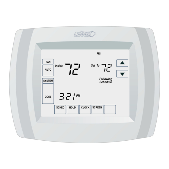
The Lennox Commercial Touchscreen Thermo-
stat provides electronic control of 24 Vac heating
and cooling systems. See Table 1 for a descrip-
.
tion
Table 1. Thermostat Description
Feature
Description
S Battery only
Powering
Methods
S Direction connection to a 24 Vac
transformer only.
S Direct connection to a 24 Vac
transformer with battery backup.
S Conventional (up to 2 heat, 2 cool
System
Types
stages)
S Heat Pump (up to 3 heat, 2 cool
stages)
Changeover
Manual or automatic changeover (se-
lectable)
System Set-
Heat−Off−Cool−Auto
tings
Auto−on
MERCURY NOTICE
If this control is replacing a control that contains
mercury in a sealed tube, do not place your old con-
trol in the trash. Dispose of properly.
Contact your local waste management authority for
instructions regarding recycling and the proper dis-
posal of an old control.
Installation
When Installing this Product...
1. Read these instructions carefully. Failure to
follow them could damage the product or
cause a hazardous condition.
2. Check ratings given in instructions and on the
product to ensure the product is suitable for
your application.
11/08
*2P1108*
COMMERCIAL
CONTROLS
505103M
11/08
Supersedes 01/2007
3. Installer must be a trained, experienced ser-
vice technician.
4. After installation is complete, check out prod-
uct operation as provided in these instruc-
tions.
Electrical Shock or Equipment Damage haz-
ard.
Can shock individuals or short equipment
circuitry.
Disconnect power supply before installation.
Select Thermostat Location
Select a location for the thermostat about 5 feet
(1.5m) above the floor in an area with good air cir-
culation at average temperature (see figure 1).
NO
Figure 1. Select Thermostat Location
Do not install the thermostat where it can be af-
fected by:
INSTALLATION
INSTRUCTIONS
Commercial Touch
Screen Thermostat
CAUTION
NO
D
Drafts or dead spots behind doors and in
corners.
D
Hot or cold air from ducts.
D
Radiant heat from sun or appliances.
D
Concealed pipes and chimneys.
D
Unheated (uncooled) areas such as an
outside wall behind the thermostat.
*P505103M*
NO
YES
5 FEET
(1.5 METERS)
505103M
Advertisement
Table of Contents
Troubleshooting

Related Manuals for Lennox Commercial TouchScreen Thermostat


Summary of Contents for Lennox Commercial TouchScreen Thermostat
- Page 1 3. Installer must be a trained, experienced ser- Application vice technician. 4. After installation is complete, check out prod- The Lennox Commercial Touchscreen Thermo- uct operation as provided in these instruc- stat provides electronic control of 24 Vac heating tions.
- Page 2 Figure 2. − Separate Wallplate from Thermostat (conventional or heat pump (see figure 4). Lennox commercial equipment does not use Install Wallplate the heat pump system terminals. Install the thermostat horizontally on the wall (see...
- Page 3 When using separate transformer for heating and cooling, the common must come from the cooling transformer. 3 Lennox commercial heat pumps do not use this terminal to energize the reversing valve. Thermostat will always be conventional type. 4 Reference economizer literature for wiring details.
-
Page 4: Power The Thermostat
SUBBASE SUBBASE UNIT TB1 THERMOSTAT 20K Ohm 10K Ohm 10K Ohm SUBBASE 10K Ohm 20K Ohm SUBBASE 20K Ohm 20K Ohm 20K Ohm 20K Ohm 20K Ohm Figure 8. Wire TG/TC/TH 090−300S Units SUBBASE UNIT TB1 THERMOSTAT 20K Ohm 20K Ohm 20K Ohm 10K Ohm 10K Ohm... - Page 5 See steps 1 through 4, in the Advanced Settings section to set year, month and day. SET CURRENT DAY SET MONTH OK TO PICK MUL TIPLE DAYS SCREEN LOCKED CHANGE FIL TER UV LAMP HUMIDIFIER P AD DONE BATTERIES (3) Figure 12.
- Page 6 3. The Setup Number displays to the lower−left Advance Settings area of the screen. It is a four−digit code begin- ning with zero. The current setting is dis- The thermostat has advanced settings to match the played to the right. HVAC system.
- Page 7 (and sends economizer to Duration 3−Three hours minimum position). Reversing 0−O (O/B On Cool) O or B setting not used with Lennox commer- 0190 Valve O/B 1−B (O/B On Heat) cial equipment. Cycles Per Only shown for system with cool stages.
- Page 8 Set for total equal resistance for 4−Remote 20K Indoor combination of sensors. 0− None 15(−9.5)−15°F(−9.5°C) Lennox commercial equipment does not use heat pump mode. Only shown for heat pump 20(− 6.5)−20°F(− 6.5°C) Heat Pump systems with more heat stages than cool 25(−...
- Page 9 Table 3. Installer Setup Menu Installer Installer Default All Settings Notes Setup No. Setup Name Setting 0− Off 2− 2 minutes Minimum Only shown if system has cool stages. Set to Compressor 0580 3− 3 minutes 0. Not needed for 3 phase systems. Off Time 4−...
-
Page 10: System Settings
Table 4. Installer Tests Table 5. Energy Star Default Program Settings Setpoints Schedule Schedule Time Time Period Setting 0−Off Heat Cool Test 1−Cool Stage 1 Test Cool 08:00 2−Cool Stage 2 Occ1 Auto Test 0−Off Test Fan 1−Fan On 10:00 Unocc1 Auto (29.5... - Page 11 Table 7. Troubleshooting Symptom Possible Cause Action Check for 24 Vac between C and Rc. Display does not come Thermostat is not being Check that AAA batteries are installed correctly and are powered. good. The upper or lower tem- Check temperature setpoints. perature limits were Check Installer Setup Numbers 0600 and 0610;...
-
Page 12: Specifications
Table 7. Troubleshooting Symptom Possible Cause Action Heating equipment is not a heat pump but System Heating equipment is run- Set System Type (Installer Setup Number 0170) to Type (Installer Setup ning in the cool mode. match the installed heating and/or cooling equipment. Number 0170) is set to Heat Pump.