Table of Contents
Advertisement
Quick Links
Technical Manual
Of
Intel Cedar Trail Series CPU
& NM10 Chipset
Based
Mini-ITX M/B
NO.G03-NF9C-F
Revision: 2.0
Release date: December, 2011
Trademark:
* Specifications and Information contained in this documentation are furnished for information use only, and are
subject to change at any time without notice, and should not be construed as a commitment by manufacturer.
Advertisement
Table of Contents

Related Manuals for JETWAY G03-NF9C-F


Summary of Contents for JETWAY G03-NF9C-F
- Page 1 Technical Manual Intel Cedar Trail Series CPU & NM10 Chipset Based Mini-ITX M/B NO.G03-NF9C-F Revision: 2.0 Release date: December, 2011 Trademark: * Specifications and Information contained in this documentation are furnished for information use only, and are subject to change at any time without notice, and should not be construed as a commitment by manufacturer.
- Page 2 Environmental Protection Announcement Do not dispose this electronic device into the trash while discarding. To minimize pollution and ensure environment protection of mother earth, please recycle.
-
Page 3: Table Of Contents
TABLE OF CONTENT ENVIRONMENTAL SAFETY INSTRUCTION................iv USER’S NOTICE ........................v MANUAL REVISION INFORMATION ..................v ITEM CHECKLIST ........................v CHAPTER 1 INTRODUCTION OF THE MOTHERBOARD FEATURE OF MOTHERBOARD................1 SPECIFICATION ......................2 LAYOUT DIAGRAM....................3 CHAPTER 2 HARDWARE INSTALLATION JUMPER SETTING ..................... -
Page 4: Environmental Safety Instruction
Environmental Safety Instruction Avoid the dusty, humidity and temperature extremes. Do not place the product in any area where it may become wet. 0 to 60 centigrade is the suitable temperature. (The figure comes from the request of the main chipset) Generally speaking, dramatic changes in temperature may lead to contact malfunction and crackles due to constant thermal expansion and contraction from the welding spots’... -
Page 5: User's Notice
USER’S NOTICE COPYRIGHT OF THIS MANUAL BELONGS TO THE MANUFACTURER. NO PART OF THIS MANUAL, INCLUDING THE PRODUCTS AND SOFTWARE DESCRIBED IN IT MAY BE REPRODUCED, TRANSMITTED OR TRANSLATED INTO ANY LANGUAGE IN ANY FORM OR BY ANY MEANS WITHOUT WRITTEN PERMISSION OF THE MANUFACTURER. -
Page 6: Chapter 1 Introduction Of The Motherboard
Chapter 1 Introduction of the Motherboard Feature of Motherboard ® Intel Cedar Trail series CPU and NM10 Chipset, with low power consumption never denies high performance Support DDRIII 800/1066 MHz SO-DIMM (N2600 series only support 800 MHz) Onboard Realtek RTL 8111E Gigabit Ethernet LAN Integrated ALC662 2-channel HD audio CODEC Support DirectX 9 Graphics Integrated LVDS... -
Page 7: Specification
Specification Spec Description Design Mini-ITX form factor 6 layers ; PCB size: 17.0 x17.0cm ® Intel NM10 Express chipset Chipset ® Intel Cedar Trail series CPU Embedded CPU 2 * SO-DIMM DDRIII slots supports DDRIII 800/1066 MHz SO-DIMM , total maximum to 4GB Note: Memory Slot –... -
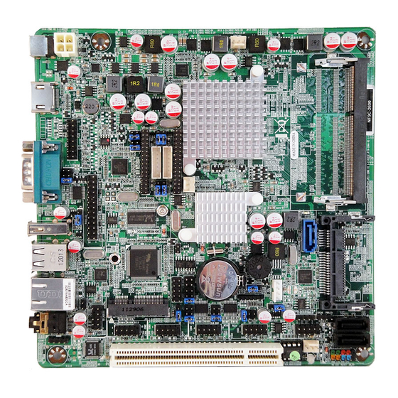
Page 8: Layout Diagram
CDIN header x1 HDMI_SPDIF header x1 Parallel port header x1 VGA port header x1 LVDS1 header x 1 and INVERTER1 x 1 (Optional) LVDS2 header x1 and INVERTER2 x 1 Serial port header x 3 RS422/RS485 header x1 GPIO header x1 Front panel header x1 3-pin Power LED header x1 Speaker header x1... - Page 9 Motherboard Internal Diagram CPU FAN Header DC12V Power Connector (J1) VGA Header Intel CPU LVDS Header HDMI (LVDS1) Connector SO-DIMM1 Slot (Optional) INVERTER1 INVERTER 2 SO-DIMM2 Slot Connector SYSFAN1 Header LVDS Header (LVDS2) Connectors Parallel Header SATAII Port Intel NM10 CFast Card Slot (SATA1) Chipset...
- Page 10 Motherboard Jumper Position (Optional) (Optional) JP13 JP14 JP12 (Optional) JBAT JP17 JP16 JP15 Note: The diagrams in the manual serve illustration purpose only. SODIMM1, LVDS1 header, INVERTER2 and Jumper JP2 ,JP3 & JP9 are only optional with specific modesl. Please refer to the product purchased for actual specification.
- Page 11 Jumper Jumper Name Description JBAT CMOS RAM Clear Function Setting 3-Pin Block USB 1/2 Power On Function Setting 3-Pin Block USB 3/4 Power On Function Setting 3-Pin Block JP2 (Optional) LVDS1 VCC 5V/3.3V Select 3-Pin Block JP3 (Optional) INVERTER1 VCC 12V/5V Select 3-Pin Block JP13 LVDS2 VCC 5V/3.3V Select...
- Page 12 Headers Header Name Description FP_AUDIO1 Front Panel Audio Header 9-Pin Block CDIN1 CD Audio-In Header 4-pin Block SPDIF SPDIF Out header 2-pin Block PARALLEL Parallel Header 25-Pin Block VGA1 Video Graphic Attach Header 15-Pin Block LVDS1(optional)/ LVDS Header 32-Pin Block LVDS2 INVERTER1(optional)/ LVDS Inverter...
-
Page 13: Hardware Installation
Chapter 2 Hardware Installation 2-1 Jumper Setting (1) JBAT (3-pin): Clear CMOS JBAT JBAT 1-2 closed: Normal 2-3 closed : Clear CMOS (2) JP1 (3-pin): USB 1/2 Power On Function Setting 1-2 closed : USB 1/2 Power on Disabled 2-3 closed: USB 1/2 Pow er on Enabled(default) - Page 14 (3) JP5 (3-pin): USB 3/4 Power On Function Setting 1-2 closed : USB 3/4 Power on Disabled 2-3 closed: USB 3/4 Power on Enabled(default) (4) JP2 (3-pin): LVDS1 VCC 5V/3.3V Function Setting 1-2 closed: LVDS1 VCC 5V(default) 2-3 closed : LVDS1 VCC 3.3V * Note: Jumper JP2 is only optional for model with LVDS1 header.
- Page 15 (5) JP3 (3-pin): INVERTER1 VCC 12V/5V Select 1-2 closed:Inverter1 VCC=12V (default) 2-3 closed:Inverter1 VCC= * Note: Jumper JP3 is only optional for model with INVERTER1 header. (6) JP13 (3-pin): LVDS2 VCC 5V/3.3V Function Setting JP13 JP13 1-2 closed: LVDS2 VCC 5V(default) 2-3 closed : LVDS2 VCC 3.3V...
- Page 16 (7) JP12 (3-pin): INVERTER2 VCC 12V/5V Select JP12 JP12 2-3 closed :Inverter2 VCC=5V 1-2 closed: Inverter2 VCC=12V (default) (8) JP14 (6-pin): COM1 Pin9 Function Select JP14 1-2 closed: RS232 3-4 closed : +12V 5-6 closed : +5V...
- Page 17 (9) JP7 (6-pin): COM2 Pin9 Function Select 1-2 closed: RS232 3-4 closed : +12V 5-6 closed : +5V (10) JP15 (6-pin): COM3 Pin9 Function Select JP15 1-2 closed: RS232 3-4 closed : +12V 5-6 closed : +5V...
- Page 18 (11) JP16 (6-pin): COM4 Pin9 Function Select JP16 1-2 closed: RS232 3-4 closed : +12V 5-6 closed : +5V (12) JP17 (6-pin): COM4 RS232/485/422 Function Select JP17 3-4 closed : RS485 5-6 closed : RS422 1-2 closed: RS232...
- Page 19 (13)COPEN (2-pin): Case Open Message Display function select COPEN 1-2 Open: Normal 1-2 Short: Case Open Case Open Display Function Pin 1-2 shorted: Case open display function enabled. In this case if you case is removed, next time when you restart your computer a message will be displayed onscreen to inform you of this.
- Page 20 (15) JP9 (8-pin): LVDS1 Panel Resolution Select Pin1 User can select Panel resolution by jumper settings. There are two basic setting modes: Short: in which user can close pin 1-pin2, pin3-pin4, pin5-pin6, pin7-pin8 respectively; Open: in which user leave jumper hat just in pin 2, pin4, pin6 or pin8. Jumper Setting Description Panel Resolution...
- Page 21 Pin 1-2: Short Pin 3-4: Short 1280 x 720 @ 60Hz 18-bit Pin 5-6: Open Pin 7-8: Short Pin 1-2: Open Pin 3-4: Short 800 x 480 @ 60Hz 18-bit Pin 5-6: Open Pin 7-8: Short Pin 1-2: Short Pin 3-4: Open 1366 x 768 @ 60Hz 18-bit...
-
Page 22: Connectors And Headers
Pin 1-2: Open Pin 3-4: Open 1920 x 1080 @ 60Hz 24-bit Pin 5-6: Open Pin 7-8: Open * Note: Jumper JP9 is only optional for model with LVDS1 header. Connectors and Headers 2-2-1 Connectors (1) Rear I/O Connectors RJ-45 LAN Port Connectors Connector HDMI... - Page 23 (2) Serial-ATA Port connector: SATA1, SATA3, SATA4 SATA1 connector is an SATAII connector that supports SATA 3Gb/s specification. SATA3 and SATA4 connectors are SATAIII connectors that support SATA 6Gb/s specification. Pin No. Definition (3) ATX12V Type Power Connector (4-pin block):J2 Pin1 Pin No.
-
Page 24: Headers
2-2-2 Headers (1) Front panel audio (9-pin): FP_AUDIO1 AUDIO1 Pin 1 Line-Out, MIC Headers (2) CD AUDIO-In Header (4-pin): CDIN1 Pin1... - Page 25 (3) HDMI-SPDIF Out header (2-pin): SPDIF HDMI_SPDIF_OUT HDMI_SPDIF Header (4) VGA Header (15-pin): VGA1 Pin2 Pin1...
- Page 26 (5) 24-bit LVDS Header (32-pin): LVDS1 (Optional) Pin 32 Pin31 Pin 2 Pin 1 LVDS1 Header Pin NO. Pin Define Pin NO. Pin Define Pin 1 LVDSB_DATAN3 Pin 2 LVDSB_DATAP3 Pin 3 LVDS_CLKBN Pin 4 LVDS_CLKBP Pin 5 LVDSB_DATAN2 Pin 6 LVDSB_DATAP2 Pin 7 LVDSB_DATAN1...
- Page 27 (6) 18-bit LVDS Header (32-pin): LVDS2 Pin 32 Pin31 Pin 2 Pin 1 LVDS2 Header Pin NO. Pin Define Pin NO. Pin Define Pin 1 Pin 2 Pin 3 Pin 4 Pin 5 Pin 6 Pin 7 Pin 8 Pin 9 Pin 10 Pin 11 LVDS_DDC_DATA...
- Page 28 (7) LVDS Inverter Header (7-pin): INVERTER1 (Optional) Pin No. Definition Backlight Pin 1 INVERTER1 Brightness (8) LVDS Inverter Header (7-pin): INVERTER2 Pin No. Definition Backlight Pin 1 INVERTER2 Brightness...
- Page 29 (9) Speaker Header (4-pin): SPEAK This 4-pin header connects to the case-mounted speaker. See the figure below. (10) Power LED Header (3-pin): PWR LED The Power LED is light on while the system power is on. Connect the Power LED from the system case to this pin header.
- Page 30 (12) PS/2 Keyboard & Mouse Header (6-pin): KBMS Pin1 (13) Serial Port Header (9-pin): COM2, COM3, COM4 Pin6 Pin5 Pin1 Serial COM Port 9-pin Block...
- Page 31 (14) RS422/485 Header (4-pin): TX-RX Pin 1 (15) USB Port Headers (9-pin): USB3, USB4 Pin 1 (16)FAN Speed Headers (3-pin): CPUFAN1, SYSFAN1, SYSFAN2 Pin1: GND Pin2: +12V fan power Pin3: Fan Speed...
- Page 32 CPUFAN1 SYSFAN1 SYSFAN2 (17) GPIO Header (10-pin): GPIO_CON GP37 GP36 GP34 GP35 GP32 GP33 GP30 GP31 Pin 1...
-
Page 33: Chapter 3 Introducing Bios
Chapter 3 Introducing BIOS Notice! The BIOS options in this manual are for reference only. Different configurations may lead to difference in BIOS screen and BIOS screens in manuals are usually the first BIOS version when the board is released and may be different from your purchased motherboard. Users are welcome to download the latest BIOS version form our official website. -
Page 34: Bios Menu Screen
BIOS Menu Screen The following diagram show a general BIOS menu screen: Menu Bar General Help Items Menu Items Current Setting Value Function Keys Instruction Function Key In the above BIOS Setup main menu, you can see several options. We will explain these options step by step in the following pages of this chapter, but let us first see a short description of the function keys you may use here:... -
Page 35: Getting Help
Press←→ (left, right) to select screen; Press ↑↓ (up, down) to choose the item you want to confirm or to modify in the main menu. Press <Enter> to select. Press <+>/<–> key when you want to modify the BIOS parameters for the active option. -
Page 36: Menu Bar
3-5 Menu Bar There are six menu bars on top of BIOS screen: Main To change system basic configuration Advanced To change system advanced configuration Chipset To change chipset configuration Boot To change boot settings Security Password settings Save & Exit Save setting, loading and exit options. - Page 37 System Date Set the date. Please use [TAB] to switch between data elements. System Time Set the time. Please use [TAB] to switch between time elements.
-
Page 38: Advanced Menu
3-7 Advanced Menu Scroll down to view more setting items…... - Page 39 Launch External PxE OpROM/Launch LAN1 PXE OpROM Use this item to enable or disable boot option for legacy network devices. Launch Storage OpROM Use this item to enable or disable boot option for legacy mass storage devices with option ROM. Onboard LAN 1 Controller Use this item to enable or disable PCI Express root port 1.
- Page 40 Use this item to enable or disable VGA palette register snooping. PERR# Generation Use this item to enable or disable PCI device to generate PERR#. SERR# Generation Use this item to enable or disable PCI device to generate SERR#. ► ACPI Settings ACPI Sleep State Use this item to select the highest ACPI sleep state the system will enter when the suspend button is pressed.
- Page 41 other OS (OS not optimized for Hyper-Threading Technology). Execute Disable Bit The optional settings are: [Disabled]; [Enabled]. Limit CPUID Maximum The optional settings are: [Disabled]; [Enabled]. This item should be set as [Disabled] for Windows XP. ► SATA Configuration SATA Controller(s) The optional settings are: [Disabled];...
- Page 42 [Manual].Select [Manual] you can set value for the following sub-item: Device Power-up delay in seconds, the delay range in from 1 to 40 seconds in one second increments. ► Super I/O Configuration ► COM1 Port Configuration/ COM2 Port Configuration Press [Enter] to make settings for the following items: Serial Port Use this item to enable or disable serial port (COM).
- Page 43 ► PC Health Status Press [Enter] to view hardware health status. ► Second Super I/O Configuration ► COM3 Port Configuration Press [Enter] to make settings for the following items: Serial Port Use this item to enable or disable serial port (COM). Change Settings Use this item to select an optimal setting for super IO device.
- Page 44 ► WatchDog Configuration WatchDog Timer Control Use this item to enable or disable WatchDog Timer Control. When set as [Enabled], the following sub-items shall appear: WatchDog Timer Value User can set a value in the range of 4 to 255. WatchDog Timer Unit The optional settings are: [Second];[Minute].
-
Page 45: Chipset Menu
CPUFAN / SYSFAN1/SYSFAN2 Idle Temp Use this item to set a degree for CPU/System fan1/ System fan2. FAN will idle speed when below this temperature. CPUFAN / SYSFAN1/SYSFAN2 Stop Temp Use this item to set a degree for CPU/System fan1/ System fan2. CPU FAN will stop when below this temperature. - Page 46 ► Host Bridge Press [Enter] to make settings for Intel IGD Configuration: Internal Graphics: Use this item to keep IGD enabled based on the setup options. The optional settings are: [Disabled]; [Auto]. IGFX-Boot Type Use this item to set the video device which will be activated during POST. This has no effect if external graphics presents.
- Page 47 USB 2.0 (EHCI) Support Use this item to enable or disable USB 2.0 (EHCI) support. The optional settings are: [Enabled]; [Disabled]. High Precision Event Timer Configuration: High Precision Timer The optional settings are: [Enabled]; [Disabled]. SLP_S4 Assertion Width Use this item to select a minimum assertion width of the SLP_S4# signal. Restore AC Power Loss Use this item to select AC power state when power is re-applied after a power failure (G3 State).
-
Page 48: Boot Menu
3-9 Boot Menu Setup Prompt Timeout Use this item to set number of seconds to wait for setup activation key. Bootup Numlock State Use this item to select keyboard numlock state. The optional settings are: [On]; [Off]. Quiet Boot The optional settings are: [Enabled]; [Disabled]. Gate A20 Active... -
Page 49: Security Menu
The optional settings are: [Upon Request]; [Always]. Option ROM Message Use this item to set display mode for option ROM. The optional settings are: [Force BIOS]; [Keep Current]. Interrupt 19 Capture The optional settings are: [Enabled]; [Disabled]. 3-10 Security Menu... -
Page 50: Save & Exit Menu
Security menu allow users to change administrator password and user password settings. 3-11 Save & Exit Menu Save Changes and Reset This item allows user to reset the system after saving the changes. Discard changes and Reset This item allows user to reset the system without saving any changes. - Page 51 Restore Defaults Use this item to restore /Load default values for all the setup options. Save as User Defaults Use this item to save the changes done so far as user defaults. Restore User Defaults Use this item to restore defaults to all the setup options.