Table of Contents
Advertisement
Quick Links
TECHNICAL MANUAL
Of
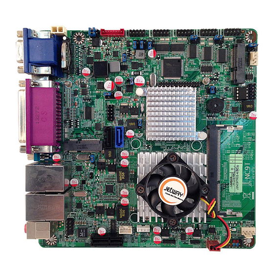
Intel 1037U CPU + Intel NM70 Chipset
Based Mini-ITX M/B
NO. G03-NC9T-F
Revision: 1.0
Release date: October 15, 2013
Trademark:
* Specifications and Information contained in this documentation are furnished for information use only, and are
subject to change at any time without notice, and should not be construed as a commitment by manufacturer.
Advertisement
Table of Contents

Related Manuals for JETWAY G03-NC9T-F


Summary of Contents for JETWAY G03-NC9T-F
- Page 1 TECHNICAL MANUAL Intel 1037U CPU + Intel NM70 Chipset Based Mini-ITX M/B NO. G03-NC9T-F Revision: 1.0 Release date: October 15, 2013 Trademark: * Specifications and Information contained in this documentation are furnished for information use only, and are subject to change at any time without notice, and should not be construed as a commitment by manufacturer.
- Page 2 Environmental Protection Announcement Do not dispose this electronic device into the trash while discarding. To minimize pollution and ensure environment protection of mother earth, please recycle.
-
Page 3: Table Of Contents
TABLE OF CONTENT ENVIRONMENTAL SAFETY INSTRUCTION................iii USER’S NOTICE ........................iv MANUAL REVISION INFORMATION ..................iv ITEM CHECKLIST ........................iv CHAPTER 1 INTRODUCTION OF THE MOTHERBOARD FEATURE OF MOTHERBOARD................1 SPECIFICATION ......................2 LAYOUT DIAGRAM....................3 CHAPTER 2 HARDWARE INSTALLATION JUMPER SETTING ..................... -
Page 4: Environmental Safety Instruction
Environmental Safety Instruction Avoid the dusty, humidity and temperature extremes. Do not place the product in any area where it may become wet. 0 to 60 centigrade is the suitable temperature. (The figure comes from the request of the main chipset) Generally speaking, dramatic changes in temperature may lead to contact malfunction and crackles due to constant thermal expansion and contraction from the welding spots’... -
Page 5: User's Notice
USER’S NOTICE COPYRIGHT OF THIS MANUAL BELONGS TO THE MANUFACTURER. NO PART OF THIS MANUAL, INCLUDING THE PRODUCTS AND SOFTWARE DESCRIBED IN IT MAY BE REPRODUCED, TRANSMITTED OR TRANSLATED INTO ANY LANGUAGE IN ANY FORM OR BY ANY MEANS WITHOUT WRITTEN PERMISSION OF THE MANUFACTURER. -
Page 6: Chapter 1 Introduction Of The Motherboard Feature Of Motherboard
Chapter 1 Introduction of the Motherboard Feature of Motherboard ® ® Intel 1037 dual-core CPU+ Intel NM70 express chipset Support 1 * DDRIII SO-DIMM 1066/1333/1600 MHz up to 8GB Support Mini-PCIE connector Support m-SATA connector Integrated with 24-bit dual channel LVDS header Support 1 * Serial ATAII (3Gb/s) &... -
Page 7: Specification
1-2 Specification Spec Description Design Mini-ITX form factor; PCB size: 17.0 x 17.0 cm ® Intel 1037U Dual Core CPU (1.8GHz) Embedded CPU ® Intel NM70 Express Chipset Chipset 1* DDRIII SO-DIMM slot Support DDRIII 1333/1600 MHz DDRIII SO-DIMM Memory Slot expandable to 8GB 1 * PCI Express x1 slot Expansion Slot... -
Page 8: Layout Diagram
1* Line-out connector 1* MIC connector Internal I/O Connectors& Headers: 1 *2-pin ATX12V internal power connector 1 *4-pin SATA power connector 3* fan connector 1* speaker connector 1* LVDS inverter connector 1 * Front panel audio header 1* speaker header 1* PWRLED connector 1 * Front panel header 1 * 9-Pin USB 2.0/1.1 header for two USB 2.0/1.1 ports... - Page 9 Motherboard Internal Diagram Serial Port Headers ATX12V (COM6/5/4/3/2) Power connector LVDS Inverter SYSFAN1 Header Half-size Mini-PCIE slot (MPE2) LVDS Header GPIO Header BUZZ USB 2.0 Header Full-size Mini-PCIE /M-SATA Selectable slot *Rear IO (MPE1) Intel NM70 Chipset SATAII Port Intel CPU (SATA2) SATAIII Port (SATA1)
- Page 10 Motherboard Jumper Position JP10 COPEN AT_MODE JP11 JP12 SYSFAN_DET JBAT...
- Page 11 Jumper Jumper Name Description JBAT CMOS RAM Clear Function Setting 3-pin Block SYSFAN_DET SYSFAN1/ SYSFAN2 R.P.M. Select 3-pin Block INVERTER Backlight VCC 5V/12V Select 3-pin Block INVERTER Backlight Mode Select 3-pin Block LCD VCC 3.3V/5V/12V Select 4-pin Block Mini-PCIE & MSATA Slot ( MPE1 ) 3-pin Block VCC 3.3V/3VSB Select JP12...
- Page 12 AUDIO(Top) Audio Line Out Connector AUDIO(Bottom) Audio MIC Connector ATXPWR 12V Power-in Connector SATAPW SATA Power out Connector SATA1 SATAIII Connector SATA2 SATAII Connector MPE1 Full-size MSATA/Mini-PCIE Connector MPE2 Half-size Mini-PCIE Connector SYSFAN1,SYSFAN2,CPUFAN FAN Connector X3 SPEAK Speaker Connector INVERTER LVDS Inverter Connector Headers Header...
-
Page 13: Hardware Installation
Chapter 2 Hardware Installation 2-1 Jumper Setting (1) JBAT (3-pin): CMOS RAM Clear Function Setting JBAT 1-2 Closed: Normal; 2-3 Closed:Clear CMOS. CMOS Clear Setting (2) SYSFAN_DET (3-pin): SYSFAN1/SYSFAN2 R.P.M. Select SYSFAN_DET 1-2 Closed: 2-3 Closed: SYSFAN1 R.P.M. Selected; SYSFAN2 R.P.M. Selected. - Page 14 (3) JP1 (3-pin): INVERTER Back Light VCC 5V /12V Select JP1→INVERTER Back Light VCC 1-2 Closed: Back Light VCC=5V; 2-3 Closed: Back Light VCC=12V. (4) JP7 (3-pin): INVERTER Back Light Mode Select JP7→INVERTER Back Light Mode 1-2 Closed: Back Light PWM Mode Selected; 2-3 Closed: Back Light DC Mode Selected.
- Page 15 (5) JP8 (4-pin): LCD Back Light VCC 3.3V/5V/12V Select JP8→LCD Back Light VCC 2 4 6 2 4 6 1 3 5 1 3 5 2-4 Closed: LVDS 3-4 Closed: LVDS 4-6 Closed: LVDS VCC= 3.3V; VCC= 5V; VCC= 12V. (6) JP2 (3-pin): MINI-PCIE &...
- Page 16 (7) JP12 (3-pin): RJ-11 VCC 12V/24V Select JP12→RJ-11 VCC 1-2 Closed: RJ11 VCC= 12V; 2-3 Closed: RJ11 VCC= 24V. (8) JP9 (4-pin): COM1 Port Pin9 Function Select JP9→COM1 Port 2 4 6 2 4 6 1 3 5 1 3 5 2-4 Closed: 3-4 Closed: 4-6 Closed:...
- Page 17 (9) JP4 (4-pin): COM2 Header Pin9 Function Select JP4→COM2 Header 2 4 6 2 4 6 1 3 5 1 3 5 2-4 Closed: 3-4 Closed: 4-6 Closed: RI=RS232; RI= 5V; RI= 12V. (10) JP3 (4-pin): COM3 Header Pin9 Function Select JP3→COM3 Header 2 4 6 2 4 6...
- Page 18 (11) JP5 (4-pin): COM4 Header Pin9 Function Select JP5→COM4 Header 2 4 6 2 4 6 1 3 5 1 3 5 2-4 Closed: 3-4 Closed: 4-6 Closed: RI=RS232; RI= 5V; RI= 12V. (12) JP10 (4-pin): COM5 Header Pin9 Function Select JP10→COM5 Header 2-4 Closed: 3-4 Closed:...
- Page 19 (13) JP11 (4-pin): COM6 Header Pin9 Function Select JP11→COM6 Header 2-4 Closed: 3-4 Closed: 4-6 Closed: RI=RS232; RI= 5V; RI= 12V. (14)JP6 (2-pin): ME Unlock Select 1-2 Open: Normal ; 1-2 Closed: ME Unlocked.
- Page 20 (15)AT_MODE (2-pin): AT Mode Function Select AT_MODE 1-2 Open: ATX Mode Selected; 1-2 Closed: AT Mode Selected. Pin 1-2 closed: AT_MODE function is enabled. User needs to restart the system for the settings to take effect. In this case your computer will automatically turns on when power supply resumes.
-
Page 21: Connectors And Headers
Pin 1-2 Closed: Case open display function enabled. Use needs to enter BIOS and enable ‘Case Open Detect’ function. In this case if you case is removed, next time when you restart your computer a message will be displayed onscreen to inform you of this. - Page 22 (3) ATXPWR (2-pin block): DC12V Power-in Connector Pin1 Pin No. Definition +12V DC_IN (4) SATAPW (4-pin):SATA Hard Disk Power-out Connector Pin 1...
- Page 23 (5) SATA1: SATAIII Port connector This connector is a high-speed SATAIII port that supports 6 GB/s transfer rate. Pin No. Defnition (6) SATA2:SATAII Port connector This connector is a high-speed SATAII port that supports 3 GB/s transfer rate. Pin No. Defnition...
- Page 24 (7) CPUFAN (4-pin)/SYSFAN1 (4-pin) /SYSFAN2 (4-pin): FAN Connectors Pin1 +12V Fan Power Fan Speed Control SYSFAN1 Pin1 CPUFAN/SYSFAN2 (8) SPEAK (4-pin): Speaker Connector Pin1 SPEAK...
-
Page 25: Headers
(9) INVERTER (8-Pin): LVDS Inverter Connector Pin No. Definition Backlight Enable Backlight Duty Backlight Power Backlight Power Pin 1 Backlight+ SW Backlight- SW INVERTER 2-2-2 Headers (1) FP_AUDIO (9-pin): Line-Out, MIC-In Header This header connects to Front Panel Line-out, MIC-In connector with cable. Pin 1 MIC2-L MIC2-R... - Page 26 (2) SPEAK1 (4-pin): Speaker Header This 4-pin header connects to the case-mounted speaker. See the figure above. SPEAK1 Pin 1 (3) PWR LED (3-pin): Power LED Header The Power LED is light on while the system power is on. Connect the Power LED from the system case to this pin header.
- Page 27 (4) FP (9-pin): Front Panel Header Pin 1 (5) F_USB (9-pin): USB 2.0 Port Header Pin 1 DATA- DATA- DATA+ DATA+...
- Page 28 (6) COM2/3/4/5/6 (9-Pin): Serial Port Headers Pin6 Pin1 Pin5 Serial Port Header (7) LVDS (30-Pin): 24-bit dual channel LVDS Header Pin 2 Pin 1 LVDS Header...
- Page 29 Pin NO. Pin Define Pin NO. Pin Define Pin 1 LVDSB_DATAN3 Pin 2 LVDSB_DATAP3 Pin 3 LVDS_CLKBN Pin 4 LVDS_CLKBP Pin 5 LVDSB_DATAN2 Pin 6 LVDSB_DATAP2 Pin 7 LVDSB_DATAN1 Pin 8 LVDSB_DATAP1 Pin 9 LVDSB_DATAN0 Pin 10 LVDSB_DATAP0 Pin 11 LVDS_DDC_DATA Pin 12 LVDS_DDC_CLK...
- Page 30 (9) LAN1_LED/LAN2_LED (2-pin): LAN Activity LED Header Pin1 LED+ LED- LAN2_LED Pin1 LAN1_LED...
-
Page 31: Chapter 3 Introducing Bios
Chapter 3 Introducing BIOS Notice! The BIOS options in this manual are for reference only. Different configurations may lead to difference in BIOS screen and BIOS screens in manuals are usually the first BIOS version when the board is released and may be different from your purchased motherboard. Users are welcome to download the latest BIOS version form our official website. -
Page 32: Bios Menu Screen
BIOS Menu Screen The following diagram show a general BIOS menu screen: Menu Bar General Help Items Current Setting Value Menu Items Function Keys BIOS Menu Screen Function Keys In the above BIOS Setup main menu of, you can see several options. We will explain these options step by step in the following pages of this chapter, but let us first see a short description of the function keys you may use here: Press←→... -
Page 33: Getting Help
Press <Enter> to select. Press <+>/<–> keys when you want to modify the BIOS parameters for the active option. [F1]: General help. [F2]: Previous value. [F3]: Optimized defaults. [F4]: Save & Reset. Press <Esc> to quit the BIOS Setup. Getting Help Main Menu The on-line description of the highlighted setup function is displayed at the top right corner the screen. -
Page 34: Main Menu
Main Menu Main menu screen includes some basic system information. Highlight the item and then use the <+> or <-> and numerical keyboard keys to select the value you want in each item. System Date Set the date. Please use [Tab] to switch between data elements. System Time Set the time. -
Page 35: Advanced Menu
3-7 Advanced Menu ERP Support The optional settings: [Enabled]; [Disabled]. Use this item to enable or disable Energy-Related Products function for this board. This item should be set as [Disabled] to activate all wake-up functions. ► ACPI Settings Press [Enter] to make settings for the following sub-items: ACPI Settings ACPI Sleep State Use this item to select the highest ACPI sleep state the system will enter when the... - Page 36 ► Wakeup function Settings Press [Enter] to make settings for the following sub-items: Wake System with Fixed Time Use this item to enable or disable system wake on alarm event. When set as [Enabled], system will wake on the hour/min/sec specified. PS2 KB/MS Wakeup The optional settings: [Enabled];...
- Page 37 ► SATA Configuration Press [Enter] to make settings for the following sub-items: SATA Controller(s) Use this item to enable or disable SATA device. The optional settings: [Enabled]; [Disabled]. SATA Mode Selection Use this item to determine how SATA controller(s) operate. The optional settings are: [IDE];...
- Page 38 [Auto]: To disable legacy support if no USB devices are connected. [Disabled]: to keep USB devices available only for EFI specification, EHCI Hand-off This is workaround for OSes without EHCI hand-off support. The EHCI ownership change should be claimed by EHCI driver. The optional settings are: [Disabled];...
- Page 39 Use this item to enable or disable serial port (COM). Change Settings Use this item to select an optimal setting for super IO device. Transmission Mode Select The optional settings are: [RS422]; [RS232]; [RS485]. Serial Port FIFO Mode The optional settings are: [16-Byte FIFO]; [32-Byte FIFO]; [64-Byte FIFO]; [128-Byte FIFO].
- Page 40 WatchDog Timer Value User can set a value in the range of 4 ~255. WatchDog Timer Unit The optional settings are: [Min.]; [Sec.]. ATX Power Emulate AT Power This item will show current AT Mode is enabled or disabled. *Note: User needs to reset the system for the settings to take effect after setting Pin 1-2 of AT_MODE jumper as closed.
- Page 41 CPUFAN / SYSFAN1/SYSFAN2 Full-Speed Duty Use this item to set CPUFAN/SYSFAN1/SYSFAN2 full speed duty. Fan will run at full speed when above the pre-set duty. CPUFAN / SYSFAN11/SYSFAN2 Idle-Speed Temperature Use this item to set CPUFAN/SYSFAN1/SYSFAN2 idle speed temperature. Fan will run at idle speed when below this temperature.
-
Page 42: Chipset Menu
3-8 Chipset Menu ► PCH-IO Configuration Press [Enter] to make settings for the following sub-items: ► USB Devices Configuration Press [Enter] to further setting USB device configuration. EHCI1/EHCI2 Use this item to control the USB EHCI (USB 2.0) functions. One EHCI controller must always be enabled. Onboard LAN1 Device/ Onboard LAN2 Device Use this item to enable or disable onboard LAN device. - Page 43 The optional settings are: [Disabled]; [Enabled];[Auto]. [Disabled]: Azalia will be unconditionally disabled; [Enabled]: Azalia will be unconditionally enabled; [Auto]: Azalia will be enabled if present, disabled otherwise. Azalia Internal HDMI Codec Use this item to enable or disable internal HDMI codec for Azalia. The optional settings are: [Enabled];...
- Page 44 The optional settings are: [128M]; [256M]; [MAX]. LCD Control Primary IGFX Boot Display Use this item to select the video device which will be activated during POST. This has no effect if external graphics present. 'Secondary boot display selection will appear based on your selection.
- Page 45 Memory Frequency Limiter Use this item to set maximum memory frequency selection in Mhz. The optional settings are: [Auto]; [1067]; [1333]. *Note: This option is only available for settings when ‘DIMM Profile’ is set as [Default DIMM profile]. ► Custom Profile Control User can press [Enter] to make customized settings for ‘DIMM Profile’.
-
Page 46: Boot Menu
3-9 Boot Menu Setup Prompt Timeout Use this item to set number of seconds to wait for setup activation key. Bootup Numlock State Use this item to select keyboard numlock state. The optional settings are: [On]; [Off]. Quiet Boot The optional settings are: [Enabled]; [Disabled]. Fast Boot The optional settings are: [Enabled];... - Page 47 *When set as [Enabled], it will only install Legacy OpROM with Legacy OS and logo will not be shown during POST. EFI driver will still be installed with EFI OS. USB Support The optional settings are: [Disabled]; [Full Initial]; [Partial Initial]. PS2 Device Support The optional settings are: [Disabled];...
-
Page 48: Security Menu
which OpROM to launch. The optional settings are: [UEFI OpROM]; [Legacy OpROM]. 3-10 Security Menu Administrator Password This item allows user to set administrator password. User Password This item allows user to set user password. -
Page 49: Save & Exit Menu
3-11 Save & Exit Menu Save Changes and Exit This item allows user to exit the system after saving the changes. Discard Changes and Exit This item allows user to exit the system without saving any changes. Restore Defaults Use this item to restore /load default values for all the setup options. Save as User Defaults Use this item to save the changes done so far as user defaults.