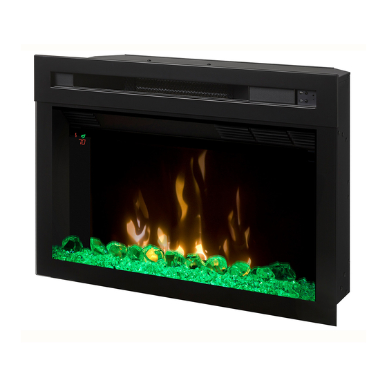
Dimplex PF2325 Service Manual
Hide thumbs
Also See for PF2325:
- Owner's manual (54 pages) ,
- Service manual (19 pages) ,
- Owner's manual (18 pages)
Table of Contents
Advertisement
Quick Links
IMPORTANT SAFETY INFORMATION: Always read this manual first before attempting to service this fireplace. For your
safety, always comply with all warnings and safety instructions contained in this manual to prevent personal injury or prop-
erty damage.
Dimplex North America Limited
1367 Industrial Road Cambridge ON Canada N1R 7G8
1-888-346-7539 www.dimplex.com
In keeping with our policy of continuous product development, we reserve the right to make changes without notice.
© 2014 Dimplex North America Limited
Service Manual
Model Number:
PF2325
PF3033
UL Part Number
690932XXXX
REV
PCN
DATE
00
-
2-OCT-14
7400790100R00
Advertisement
Table of Contents

Related Manuals for Dimplex PF2325


Summary of Contents for Dimplex PF2325
- Page 1 Dimplex North America Limited 2-OCT-14 1367 Industrial Road Cambridge ON Canada N1R 7G8 1-888-346-7539 www.dimplex.com In keeping with our policy of continuous product development, we reserve the right to make changes without notice. © 2014 Dimplex North America Limited 7400790100R00...
-
Page 2: Table Of Contents
NOTE: Procedures and techniques that are considered important enough to emphasize. CAUTION: Procedures and techniques which, if not carefully followed, will result in damage to the equipment. WARNING: Procedures and techniques which, if not carefully followed, will expose the user to the risk of fire, serious injury, or death. www.dimplex.com... -
Page 3: Operation
OPERATION It is recommended that a straightened paperclip be used to press the button through the small hole. When the gWave controls are turned off, the green light will flash 4 times WARNING: This electric firebox must be properly in- before turning off and it will remain solid green when the stalled before it is used. - Page 4 The Boost can be set for a maximum of 20 minutes, Checking Software Level in 5 minute increments. The revision can be checked by press at the Multi-Fire XD™: Scrolls through the different same time. media theme color presets for the media, flame base and top lights. www.dimplex.com...
-
Page 5: Maintenance
CAUTION: If you need to continuously reset the heater, optimal performance is maintained. The grille can be disconnect power and call Dimplex customer service at cleaned by vacuuming off all dust and dirt. 1-888-DIMPLEX (1-888-346-7539). -
Page 6: Exploded Parts Diagram - Pf2325
EXPLODED PARTS DIAGRAM - PF2325 Replacement Parts: 10. Media Tray - Flat ..... . 0441580100RP Flicker Motor ......2000480100RP Curved . -
Page 7: Exploded Parts Diagram - Pf3033
EXPLODED PARTS DIAGRAM - PF3033 Replacement Parts: Flicker Motor ......2000480100RP 10. Media Tray ......0441580200RP Heater Assembly (with cutouts) . -
Page 8: Wiring Diagram
TOP LIGHT ASSY MOTOR T2 HEATER ASSEMBLY J7 GESTURE GESTURE ASSY FLICKER MOTOR NEUTRAL T7 MAIN TO GESTURE HARNESS J5 FLAME 1W DISPLAY J8 FLAME LED ASSY TYPE OF CONNECTIONS IS BASED ON TYPE OF FIREBOX DISPLAY BOARD ASSY www.dimplex.com... -
Page 9: Main Control Board Replacement
MAIN CONTROL BOARD REPLACEMENT 4. Remove the 14 screws around the back panel of the firebox and the 3 along the middle of the panel (Figure Tools Required: Phillips Head Screwdriver Flat Head Screwdriver 5. Locate the main control board and transfer the wir- Needle Nose Pliers ing connections from the old board to the new board. -
Page 10: Floating Display Assembly Replacement
3. Remove the loose media from the unit (if applicable). 4. Remove the 14 screws around the back panel of the firebox and the 3 along the middle of the panel (Figure Bottom Mounting Screws www.dimplex.com... -
Page 11: Power Cord Replacement
POWER CORD REPLACEMENT ing bracket to the unit. 7. Locate and disconnect the 2 motor assembly wires go- Tools Required: Phillips Head Screwdriver ing to the main control board. Needle Nose Pliers 8. Remove the 2 motor mounting screws. CAUTION: If unit was operating prior to servicing allow at least 10 minutes for heating elements and top panel to 9. -
Page 12: Electronics Junction Board Replacement
4. Gently place the unit its back to expose the bottom at least 10 minutes for heating elements and top panel to of the unit. Remove the 4 screws from bottom and 2 cool off to avoid accidental burning of skin. www.dimplex.com... - Page 13 WARNING: Disconnect power before attempting any maintenance to reduce the risk of electric shock or damage to persons. 1. Unplug the unit from power outlet. 2. Remove the firebox from the front of the mantel and remove front glass assembly (glass lifts off). CAUTION: Even though the glass is safety glass it may break if bumped, struck of dropped.
-
Page 14: Troubleshooting Guide
Media LED light assembly or Replace media LED light assembly or Media logset is not working logset 23” - 3001330300RP 30” - 3001330500RP Defective electronics junction Replace electronics junction board 3001460100RP board Defective main control board Replace the main control board 3001260100RP www.dimplex.com... - Page 15 PROBLEM CAUSE SOLUTION PART NUMBER Heater Heater is not turning on, but Improper operation Refer to Operation Section flame effect is still function- Loose wiring Trace wiring in unit Defective main control board Replace the main control board 3001260100RP Defective heater assembly Replace heater assembly 2203650100RP Heater is turning off after a...