
Related Manuals for Toro TimeCutter MX 3450 74750


Summary of Contents for Toro TimeCutter MX 3450 74750
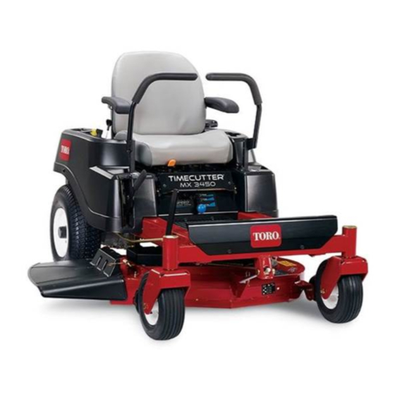
- Page 1 Form No. 3393-843 Rev A TimeCutter ® MX 3450 Riding Mower Model No. 74750—Serial No. 315000001 and Up *3393-843* A Register at www.Toro.com. Original Instructions (EN)
-
Page 2: Figure 1
California to cause cancer, birth defects, product properly and safely. or other reproductive harm. You may contact Toro directly at www.Toro.com for product Important: This engine is not equipped with a spark safety and operation training materials, accessory information, arrester muffler. It is a violation of California Public help finding a dealer, or to register your product. -
Page 3: Table Of Contents
Contents Cleaning and Storage ..........44 Troubleshooting ............46 Safety ................4 Schematics ..............48 Safe Operating Practices........... 4 Toro Riding Mower Safety ........6 Slope Indicator ............7 Safety and Instructional Decals ......... 8 Product Overview ............12 Controls ...............12 Operation ..............14 Adding Fuel............14 Using Stabilizer/Conditioner ........14... -
Page 4: Safety
In these instances, others from serious injury. Toro has refined the statement to convey the meaning of the standard while better matching the product this Operator's •... - Page 5 Service • Always avoid sudden starting or stopping on a slope. If tires lose traction, stop the machine, disengage the blades Safe Handling of Gasoline and proceed slowly off the slope. To avoid personal injury or property damage, use extra care •...
-
Page 6: Toro Riding Mower Safety
Removing standard original equipment parts and accessories may alter the warranty, traction, and safety of the machine. Failure to use original Toro parts could cause serious injury or death. Making unauthorized changes to the engine, fuel or venting system, may violate regulations. -
Page 7: Slope Indicator
Slope Indicator G011841 Figure 3 This page may be copied for personal use. 1. The maximum slope you can safely operate the machine on is 15 degrees. Use the slope chart to determine the degree of slope of hills before operating. Do not operate this machine on a slope greater than 15 degrees. Fold along the appropriate line to match the recommended slope. -
Page 8: Safety And Instructional Decals
Safety and Instructional Decals Safety decals and instructions are easily visible to the operator and are located near any area of potential danger. Replace any decal that is damaged or lost. 93-7009 1. Warning—don't operate the mower with the deflector up or removed;... - Page 9 119-8814 1. Parking position 4. Neutral 2. Fast 5. Reverse 3. Slow 121-2989 1. Bypass lever position for 2. Bypass lever position for pushing the machine operating the machine 119-8815 1. Parking position 4. Neutral 2. Fast 5. Reverse Manufacturer's Mark 3.
- Page 10 121-0771 1. Choke 4. Slow 2. Fast 5. Power take-off (PTO), Blade control switch 3. Continuous variable setting Battery Symbols Some or all of these symbols are on your battery 1. Explosion hazard 6. Keep bystanders a safe distance from the battery. 2.
- Page 11 131–3947 1. Trim—slow 3. Mow—fast 2. Tow—medium 132-0869 1. Warning—read the 3. Cutting hazard of hand, 5. Ramp tipping 7. Tipping hazard on Operator's Manual. mower blade; pinching hazard—when loading slopes—do not use on hazard of hand, belt—keep onto a trailer, do not use slopes near open water;...
-
Page 12: Product Overview
Product Overview 10 9 g027889 Figure 4 1. Deflector 4. Operator seat 7. Footrest 10. Height of cut lever 2. Rear drive wheel 5. Motion control levers 8. Front caster wheel 3. Control panel 6. Smart Speed™ lever 9. Lift-assist lever Controls Ignition Switch Become familiar with all of the controls in... -
Page 13: Hour Meter
Motion Control Levers and Parking Height-of-Cut Lever Brake Position The height of cut lever allows the operator to lower and raise the deck from the seated position. When the lever is The motion control levers are speed sensitive controls of moved up, toward the operator the deck is raised from the independent wheel motors. -
Page 14: Operation
Operation DANGER In certain conditions during fueling, static Note: Determine the left and right sides of the machine electricity can be released causing a spark which from the normal operating position. can ignite the gasoline vapors. A fire or explosion from gasoline can burn you and others and can Adding Fuel damage property. -
Page 15: Filling The Fuel Tank
Filling the Fuel Tank Think Safety First Note: Ensure that the engine is shut off and the motion Operating Safety controls are in the parked position. Please carefully read all of the safety instructions and decals Note: You can use the fuel window to verify the presence of in the safety section. - Page 16 5. Try starting the engine; the engine should not crank. CAUTION 6. Repeat with the other motion-control lever. This machine produces sound levels in excess of 85 dBA at the operators ear and can cause hearing loss 7. While sitting on the seat, move the blade-control through extended periods of exposure.
-
Page 17: Starting The Engine
Starting the Engine Operating the Blades Important: Do not engage the starter for more than The blade control switch, represented by a power take-off (PTO) symbol, engages and disengages power to the mower 5 seconds at a time. If the engine fails to start, allow a blades. -
Page 18: Driving The Machine
Using the Smart Speed Control 3. Turn the ignition key to Off (Figure 5) and remove the key. System The Smart Speed Control-System lever, located below the Driving the Machine operating position (Figure 16), gives the operator a choice to drive the machine at 3 ground speed ranges—trim, tow, Driving the machine benefits from an understanding of and mow. -
Page 19: Stopping The Machine
Driving Backward Note: Always use caution when backing up and turning. This is the medium speed. The suggested uses for this speed are as follows: 1. Move the levers to the center, unlocked position. • Bagging 2. To go backward, look behind you and down, as you •... -
Page 20: Adjusting The Height-Of-Cut
Adjusting the Height-of-Cut Note: The transport position is the highest height-of-cut position or cutting height (115 mm (4.5 inches)) as shown Figure Height-of-cut is controlled by the lever located to the right of the operating position (Figure 19). Figure 20 Adjusting the Anti-Scalp Rollers Whenever you change the height-of-cut, adjust the height... -
Page 21: Adjusting The Motion Control Levers
Adjusting the Motion Control 5. Move the motion control levers inward to the neutral position and turn the ignition key to the run position. Levers Do not start the machine. The machine is now able to be pushed by hand. Adjusting the Height The motion control levers can be adjusted higher or lower for maximum operator comfort... -
Page 22: Grass Deflector
Grass Deflector The mower has a hinged grass deflector that disperses clippings to the side and down toward the turf. DANGER Without the grass deflector, discharge cover, or complete grass catcher assembly mounted in place, you and others are exposed to blade contact Figure 24 and thrown debris. - Page 23 WARNING Loading a machine onto a trailer or truck increases the possibility of tip-over and could cause serious injury or death. • Use extreme caution when operating a machine on a ramp. • Use only a full-width ramp; do not use individual ramps for each side of the machine.
-
Page 24: Operating Tips
If a blade is damaged or worn, replace it six inches tall, you may want to cut the lawn twice to ensure immediately with a genuine Toro replacement blade. an acceptable quality of cut. Cut 1/3 of the Grass Blade It is best to cut only about 1/3 of the grass blade. -
Page 25: Maintenance
Maintenance Note: Determine the left and right sides of the machine from the normal operating position. Recommended Maintenance Schedule(s) Maintenance Service Maintenance Procedure Interval • Change the engine oil. After the first 5 hours • Check the safety-interlock system. • Clean and check the air cleaner foam element. •... -
Page 26: Premaintenance Procedures
Premaintenance Lubrication Procedures Greasing the Bearings Raising the Seat Service Interval: Every 25 hours—Grease all lubrication points. Make sure the motion control levers are locked in the park Grease Type: No. 2 general purpose, lithium-based grease position. Lift the seat forward. 1. -
Page 27: Engine Maintenance
Engine Maintenance 4. Connect a grease gun to each fitting (Figure 27 Figure 28). Pump grease into the fittings until grease begins to ooze out of the bearings. Servicing the Air Cleaner 5. Wipe up any excess grease. Service Interval: Before each use or daily—Clean and check the air cleaner foam element. -
Page 28: Servicing The Engine Oil
Servicing the Engine Oil Oil Type: Detergent oil (API service SF, SG, SH, SJ, or higher) Crankcase Capacity: 1.0 L (34 oz) when you do not change the filter; 1.05 L (36 oz) when you change the filter. Viscosity: See the table below. Figure 30 1. - Page 29 Changing the Engine Oil Service Interval: After the first 5 hours Every 100 hours (change it more often under a heavy load or in high temperatures). 1. Park the machine, so that the right side is slightly lower than the left side, to ensure that the oil drains completely.
- Page 30 Changing the Engine-Oil Filter Service Interval: Every 100 hours Note: Change the engine-oil filter more frequently when the operating conditions are extremely dusty or sandy. 1. Drain the oil from the engine; refer to Changing the Engine Oil (page 29). g027484 Figure 34 5.
-
Page 31: Servicing The Spark Plug
Servicing the Spark Plug Installing the Spark Plug Tighten the spark plug to 20 N-m (15 ft-lb). Service Interval: Every 50 hours—Check the spark plug. Every 100 hours—Replace the spark plug. Ensure that the air gap between the center and side electrodes is correct before installing the spark plug. -
Page 32: Fuel System Maintenance
Fuel System Maintenance DANGER In certain conditions, gasoline is extremely g027506 flammable and highly explosive. A fire or explosion from gasoline can burn you and others and can damage property. • Perform any fuel related maintenance when the engine is cold. Do this outdoors in an open area. Wipe up any gasoline that spills. -
Page 33: Electrical System Maintenance
Electrical System 5. Slide the rubber cover up the positive (red) cable. Disconnect the positive (red) cable from the battery Maintenance post (Figure 40). Retain all fasteners. 6. Remove the battery hold-down (Figure 40) and lift the battery from the battery tray. WARNING CALIFORNIA Proposition 65 Warning... -
Page 34: Servicing The Fuses
Figure 41 1. Positive battery post 3. Red (+) charger lead G014921 2. Negative battery post 4. Black (-) charger lead Figure 42 1. Main—30 amp 2. Charge circuit—25 amp Installing the Battery 4. Return the control panel to its original position. Use 1. -
Page 35: Drive System Maintenance
Drive System 2. Locate the shaft on the electric brake where the brake-link arms are connected. Maintenance 3. Rotate the shaft forward to release the brake. Checking the Tire Pressure Service Interval: Every 25 hours—Check tire pressure. Maintain the air pressure in the front and rear tires as specified. -
Page 36: Mower Maintenance
If a blade is damaged or worn, replace 2. Curved area 4. Damage it immediately with a genuine Toro replacement blade. For convenient sharpening and replacement, you may want to keep extra blades on hand. Checking for Bent Blades... - Page 37 (1/8 inch), the blade spindle could be bent. 3. Opposing side of blade being moved into measurement position Contact an Authorized Toro Dealer for service. B. If the variance is within constraints, move to the next blade.. 5. Measure from the tip of the blade to the flat surface here.
-
Page 38: Leveling The Mower Deck
To ensure optimum performance and continued safety conformance Figure 52 of the machine, use genuine Toro replacement blades. Replacement blades made by other manufacturers may result 1. Blade 2. Balancer in non-conformance with safety standards. -
Page 39: Adjusting The Front-To-Rear Blade Slope
10. Continue leveling the deck by checking the front-to-rear blade slope; refer to Releasing the Electric Brake (page 35). G009682 Adjusting the Front-to-Rear Blade Slope Check the front-to-rear blade level any time you install the mower. If the front of the mower is more than 7.9 mm (5/16 inch) lower than the rear of the mower, adjust the blade level using the following instructions: 1. -
Page 40: Removing The Mower
G014634 Figure 56 1. Adjusting rod 3. Lock nut 2. Adjusting block G014635 Figure 57 7. To raise the front of the mower, tighten the adjustment nut. To lower the front of the mower, loosen the 1. Front support rod 3. -
Page 41: Mower Belt Maintenance
Figure 59 [1-1/2 inch (38 mm)]. 1. Idler pulley 5. Engine pulley 4. Using a spring removal tool, (Toro part no. 92-5771), 2. Mower belt 6. Spring removal tool remove the idler spring from the deck hook to remove 3. Outside pulley 7. -
Page 42: Replacing The Grass Deflector
Replacing the Grass Deflector Service Interval: Before each use or daily—Inspect the grass deflector for damage WARNING An uncovered discharge opening could allow the lawn mower to throw objects in the operator’s or bystander’s direction and result in serious injury. Also, contact with the blade could occur. -
Page 43: Cleaning
Cleaning Washing the Underside of the Mower Service Interval: After each use—Clean the mower housing. Important: You can wash the machine with mild detergent and water. Do not pressure wash the machine. Avoid excessive use of water, especially near the control panel, under the seat, around the engine, hydraulic pumps, and motors. -
Page 44: Storage
Storage Note: If the mower is not clean after one washing, soak it and let it stand for 30 minutes. Then repeat the process. Cleaning and Storage 8. Run the machine and mower blades again for one to 1. Disengage the blade control switch, move the motion three minutes to remove excess water. - Page 45 14. Check the condition of the drive and mower belts. 15. Check and tighten all bolts, nuts, and screws. Repair or replace any part that is worn or damaged. 16. Paint all scratched or bare metal surfaces. Paint is available from your Authorized Service Dealer. 17.
-
Page 46: Troubleshooting
Troubleshooting Problem Possible Cause Corrective Action The engine overheats. 1. The engine load is excessive. 1. Reduce ground speed. 2. The oil level in the crankcase is low. 2. Add oil to the crankcase. 3. The cooling fins and air passages 3. - Page 47 Problem Possible Cause Corrective Action There is abnormal vibration. 1. The engine mounting bolts are loose. 1. Tighten the engine mounting bolts. 2. The engine pulley, idler pulley, or blade 2. Tighten the appropriate pulley. pulley is loose. 3. The engine pulley is damaged. 3.
-
Page 48: Schematics
Schematics Electrical Diagram (Rev. A) - Page 49 Notes:...
- Page 50 Notes:...
- Page 51 Notes:...
- Page 52 Toro importer. If all other remedies fail, you may contact us at Toro Warranty Company. Australian Consumer Law: Australian customers will find details relating to the Australian Consumer Law either inside the box or at your local Toro Dealer.