Toro 04520 Operator's Manual
Traction unit
Hide thumbs
Also See for 04520:
- Operator's manual (52 pages) ,
- Service manual (332 pages) ,
- Operator's manual (48 pages)

Related Manuals for Toro 04520


Summary of Contents for Toro 04520
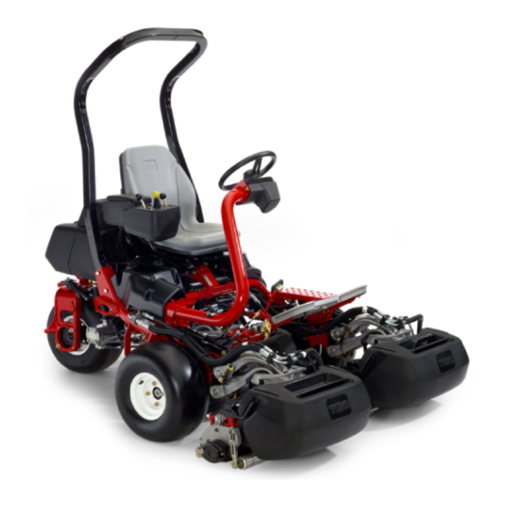
- Page 1 Form No. 3380-291 Rev A Greensmaster ® 3400 TriFlex ™ Traction Unit Model No. 04520—Serial No. 314000001 and Up g014597 *3380-291* A Register at www.Toro.com. Original Instructions (EN)
-
Page 2: Introduction
You are responsible for operating the product properly and safely. You may contact Toro directly at www.Toro.com for product and accessory information, help finding a dealer, or to register your product. Whenever you need service, genuine Toro parts, or additional... -
Page 3: Table Of Contents
Adjusting the Mowing Speed........40 Safety ................4 Cooling System Maintenance ........41 Safe Operating Practices........... 4 Cleaning the Radiator Screen........41 Toro Mower Safety ..........6 Brake Maintenance ............42 Sound Power Level ..........8 Adjusting the Brakes ..........42 Sound Pressure Level..........8 Belt Maintenance ............42... -
Page 4: Safety
Safety ◊ The owner/user can prevent and is responsible for accidents or injuries occurring to himself or herself, other people, or property This machine meets or exceeds CEN standard EN 836:1997, ISO standard 5395:1990, and ANSI B71.4-2004 Preparation specifications in effect at the time of production when 16.8 kg (37 lb) of weight is added to the rear wheel. - Page 5 • interlocks are attached, adjusted properly, and functioning Be certain that the seat belt can be released quickly in properly. the event of an emergency. • Do not change the engine governor settings or overspeed • Check the area to be mowed and never fold down a the engine.
-
Page 6: Toro Mower Safety
Set the parking brake. Stop the engine and remove the key from the ignition switch. The following list contains safety information specific to Toro • products or other safety information that you must know that Traverse slopes carefully. - Page 7 Keep everyone away. • To ensure safety and accuracy, have an Authorized Toro Distributor check the maximum engine speed with a tachometer. Maximum governed engine speed should be 2900 rpm.
-
Page 8: Sound Power Level
Sound Power Level Hand-Arm Vibration Level This unit has a guaranteed sound power level of 98 dBA, Measured vibration level for right hand = 0.22 m/s which includes an Uncertainty Value (K) of 1 dBA. Measured vibration level for left hand = 0.24 m/s Sound power level was determined according to the Uncertainty Value (K) = 0.24 m/s procedures outlined in ISO 11094. - Page 9 115-8156 1. Reel height 3. 8 Blade cutting unit 5. 14 Blade cutting unit 7. Fast 2. 5 Blade cutting unit 4. 11 Blade cutting unit 6. Reel speed 8. Slow 117–2718 115-8155 1. Warning—read the Operator's Manual, do not prime or use starting fluid.
- Page 10 Battery Symbols Some or all of these symbols are on your battery. 1. Explosion hazard 6. Keep bystanders a safe distance from the battery. 2. No fire, open flames, or 7. Wear eye protection; 121–5172 smoking. explosive gases can cause blindness and other 1.
- Page 11 121–2640 1. Warning—read the 4. Tipping hazard—do not Operator’s Manual, do drive across slopes greater not operate this machine than 15 degrees or down unless you are trained. slopes greater than 15 degrees. 2. Thrown object 5. Warning—lock the parking hazard—keep bystanders brake, stop the engine a safe distance from the...
-
Page 12: Setup
Setup Loose Parts Use the chart below to verify that all parts have been shipped. Procedure Description Qty. Roll bar Bolt (1/2 x 3-3/4 inches) Install the roll bar. Flange-nut (1/2 inch) Seat completion kit Install the seat to the base. Steering wheel Locknut (1-1/2 inches) Install the steering wheel. -
Page 13: Installing The Roll Bar
Installing the Roll Bar Installing the Seat Parts needed for this procedure: Parts needed for this procedure: Seat completion kit Roll bar Bolt (1/2 x 3-3/4 inches) Procedure Flange-nut (1/2 inch) Acquire your desired seat kit from your distributor and install it as directed in the instruction included with the kit. -
Page 14: Activating And Charging The Battery
Activating and Charging the Battery No Parts Required Procedure Use only electrolyte (1.265 specific gravity) to fill battery Figure 6 initially. 1. Electrolyte 1. Remove the fasteners and battery clamp and lift out the battery. 4. Allow approximately 20 to 30 minutes for the Important: Do not add electrolyte while the electrolyte to soak into the plates. -
Page 15: Installing The Oil Cooler (Optional)
WARNING Battery terminals or metal tools could short against metal tractor components causing sparks. Sparks can cause the battery gasses to Installing the Oil Cooler explode, resulting in personal injury. (optional) • When removing or installing the battery, do not allow the battery terminals to touch any metal parts of the tractor. -
Page 16: Installing The Cutting Units
2. The cutting unit is shipped without a front roller. Obtain a roller (Model No. 04625, 04626 or 04627) from your local Toro Distributor. Install the roller using the loose parts supplied with the cutting unit and installation instructions included with the roller. - Page 17 g01461 1 Figure 12 1. Suspension-arm bar 2. Cutting-unit bar 6. Close the latches down and around the cutting-unit bar and lock them in place (Figure 11). Note: A “click” can be heard and felt when the latches are properly locked in place. 7.
-
Page 18: Adding Rear Weight
Product Overview Adding Rear Weight Parts needed for this procedure: Weight kit, 121–6665 (purchase separately) Note: This kit is not required for units with the 3 wheel drive kit installed. Procedure This unit complies with the ANSI B71.4-2004 and EN 836 Standards when equipped with weight kit 121–6665. -
Page 19: Throttle Control
g014603 g014599 Figure 15 Figure 17 1. Traction pedal—forward 3. Steering arm locking pedal 1. Throttle control 6. Battery warning light 2. Taction pedal—reverse 2. Raise/Lower Mow Control 7. Service indicator light 3. Functional control lever 8. Glow plug indicator light 4. -
Page 20: Engine Oil Pressure Light
Engine Oil Pressure Light Parking Brake Lever The light (Figure 17) glows if the engine oil pressure drops Pull up on the brake lever (Figure 15) to set the parking below a safe level. brake. Disengage it by pushing it forward and down. Lock the parking brake any time you leave the machine. -
Page 21: Fuel Shutoff Valve
Fuel Shutoff Valve Close the fuel shutoff valve (Figure 23), behind the seat and under the fuel tank, when storing or transporting the machine on a truck or trailer. g014623 Figure 21 1. Reel speed control Seat Adjusting Lever The seat adjusting lever is located on the front, right corner g01462 6 of the seat (Figure 22), allowing you to adjust the seat fore Figure 23... -
Page 22: Specifications
Contact your Authorized Service Dealer or Distributor or go to www.Toro.com for a list of all approved Use high-quality engine oil that meets the following attachments and accessories. -
Page 23: Filling The Fuel Tank
Filling the Fuel Tank is necessary to permit venting when filling, which prevents oil from overrunning into breather. Use only clean, fresh diesel fuel or biodiesel fuels with low (<500 ppm) or ultra low (<15 ppm) sulfur content. The minimum cetane rating should be 40. Purchase fuel in quantities that can be used within 180 days to ensure fuel freshness. -
Page 24: Using Biodiesel Fuel
1. Clean around the fuel tank cap (Figure 26). DANGER In certain conditions, fuel is extremely flammable and highly explosive. A fire or explosion from fuel can burn you and others and can damage property. • Fill the fuel tank outdoors, in an open area, when the engine is cold. -
Page 25: Checking The Cooling System
Toro Premium All Season Hydraulic Fluid (Available in 5 1. Park the machine on a level surface. gallon pails or 55 gallon drums. See parts catalog or Toro distributor for part numbers.) 2. Check the coolant level (Figure 28). It should be... - Page 26 EnviroSyn 46H Important: Mobil EAL EnviroSyn 46H is the only synthetic biodegradable fluid approved by Toro. This fluid is compatible with the elastomers used in Toro hydraulic systems and is suitable for a wide-range of temperature conditions. This fluid is compatible...
-
Page 27: Draining Water From The Fuel Filter
Filling the Hydraulic Tank 1. Position the machine on a level surface. Make sure the machine has cooled down so the oil is cold. 2. Remove the cap from the reservoir (Figure 29). g014720 Figure 30 1. Fuel filter 2. Drain plug g014719 Figure 29 Checking the Tire Pressure... -
Page 28: Break-In Period
Break-in Period two minutes. Turn the steering wheel to the left and right to check the steering response. Then Refer to the Engine Manual supplied with the machine for oil shut the engine off (see Stopping in Starting and change and maintenance procedures recommended during Stopping the Engine) and wait for all moving parts the break-in period. -
Page 29: Installing And Removing The Cutting Units
Installing and Removing the 2. Sit on the seat, move the traction pedal to Neutral, move the functional control lever to Neutral, and Cutting Units engage the parking brake. Move the functional control lever to mow or transport and try to start the engine. The engine should not crank, which means that the Installing the Cutting Units interlock system is operating correctly. - Page 30 g01461 1 Figure 33 1. Suspension-arm bar 2. Cutting-unit bar 4. Close the latches down and around the cutting-unit bar and lock them in place (Figure 32). Note: A “click” can be heard and felt when the latches are properly locked in place. 5.
-
Page 31: Setting The Reel Speed
Removing the Cutting Units 5. Disconnect the latches from the cutting-unit bar. 1. Park the machine on a clean level surface, lower 6. Roll the cutting unit out from under the suspension the cutting units to the ground until the suspension arm. -
Page 32: Mowing With The Machine
an imaginary sight line approximately 1.8 to 3 m (6 to 10 ft) ahead of the machine to the edge of the uncut portion of the green (Figure 39). Some find it useful to include the outer edge of the steering wheel as part of the sight line;... -
Page 33: Transporting The Machine
Towing the Machine In case of an emergency the machine can be towed for a short distance (less than 0.4 km (1/4 mile)). However, Toro does not recommend this as standard procedure. Important: Do not tow the machine faster than 3-5... -
Page 34: Maintenance
Note: Looking for an Electrical Schematic or Hydraulic Schematic for your machine? Download a free copy of the schematic by visiting www.Toro.com and searching for your machine from the Manuals link on the home page. Note: Determine the left and right sides of the machine from the normal operating position. -
Page 35: Daily Maintenance Checklist
Daily Maintenance Checklist Duplicate this page for routine use. Maintenance Check Item For the week of: Mon. Tues. Wed. Thurs. Fri. Sat. Sun. Check the safety interlock operation. Check the instrument operation Check the brake operation. Check the fuel filter/water separator. -
Page 36: Engine Maintenance
Engine Maintenance 4. Clean the dirt ejection port located in the removable cover. Remove the rubber outlet valve from the cover, clean the cavity and replace the outlet valve. Servicing the Air Cleaner 5. Install the cover orienting the rubber outlet valve in a downward position—between approximately 5:00 to Service Interval: Every 200 hours 7:00 when viewed from the end. -
Page 37: Fuel System Maintenance
Fuel System 3. Screw the filter on by hand until the gasket contacts the filter adapter, then tighten 1/2 to 3/4 turn further. Maintenance Do not overtighten. 4. Add oil to the crankcase; refer to Checking the Engine Oil (page 22). Servicing the Fuel Filter/Water 5. -
Page 38: Inspecting The Fuel Lines And Connections
Electrical System Maintenance Servicing the Battery WARNING CALIFORNIA Proposition 65 Warning g014720 Battery posts, terminals, and related Figure 45 accessories contain lead and lead compounds, 1. Fuel filter /water separator 2. Filter drain plug chemicals known to the State of California canister to cause cancer and reproductive harm. -
Page 39: Storing The Battery
Locating the Fuses WARNING Battery terminals or metal tools could short against The fuses in the machine’s electrical system are located under metal tractor components causing sparks. Sparks the seat (Figure 46). can cause the battery gasses to explode, resulting in personal injury. -
Page 40: Drive System Maintenance
Adjusting the Transport Speed Drive System Maintenance The traction pedal is adjusted for maximum transport speed at the factory, but an adjustment may be required if the pedal reaches full stroke before it contacts the pedal stop, or if a decrease in transport speed is desired. -
Page 41: Cooling System Maintenance
Cooling System Maintenance Cleaning the Radiator Screen To prevent the system from overheating, the radiator screen and radiator must be kept clean. Check and clean the screen and radiator daily or, if necessary, hourly. Clean these components more frequently in dusty, dirty conditions. 1. -
Page 42: Brake Maintenance
Brake Maintenance Belt Maintenance Adjusting the Brakes Adjusting the Alternator Belt If the brake fails to hold the machine while parked, you can Service Interval: After the first 8 hours adjust the brakes using the bulkhead fitting near the brake Make sure the belt is properly tensioned to ensure proper drum;... -
Page 43: Hydraulic System Maintenance
Every 800 hours and fittings are tight before applying pressure to the hydraulic system. If the oil becomes contaminated, contact your local Toro distributor because the system must be flushed. Contaminated • Keep your body and hands away from pin oil looks milky or black when compared to clean oil. -
Page 44: Cutting Unit Maintenance
Cutting Unit Maintenance Backlapping the Reels WARNING Contact with the reels or other moving parts can result in personal injury. • Keep fingers, hands, and clothing away from the reels or other moving parts. • Never attempt to turn the reels by hand or foot while the engine is running. -
Page 45: Diagnostics System
Diagnostics System Storage If you wish to store the machine for a long period of time, the Diagnosing the Service following steps should be performed prior to storage: Indicator Light 1. Remove accumulations of dirt and old grass clippings. Sharpen the reels and bedknives, if necessary; refer to The service indicator light illuminates in the event of a the Cutting Unit Operator's Manual. - Page 46 Notes:...
- Page 47 Notes:...
-
Page 48: The Toro Total Coverage Guarantee
Countries Other than the United States or Canada Customers who have purchased Toro products exported from the United States or Canada should contact their Toro Distributor (Dealer) to obtain guarantee policies for your country, province, or state. If for any reason you are dissatisfied with your Distributor's service or have difficulty obtaining guarantee information, contact the Toro importer.