AMX MVP-9000i Operation And Reference Manual
9" modero viewpoint touch panel with intercom
Hide thumbs
Also See for MVP-9000i:
- Quick start manual (2 pages) ,
- Quick start manual (2 pages) ,
- Installation manual (2 pages)

Related Manuals for AMX MVP-9000i


Summary of Contents for AMX MVP-9000i
- Page 1 Operation/Reference Guide MVP-9000i ® ® 9" Modero ViewPoint Touch Panel with Intercom Touch Panels L a s t R e v i s e d : 3 / 2 6 / 2 0 1 3...
- Page 2 AMX is not responsible for products returned without a valid RMA number. AMX is not liable for any damages caused by its products or for the failure of its products to perform. This includes any lost profits, lost savings, incidental damages, or consequential damages.
- Page 3 LICENSE GRANT. AMX grants to Licensee the non-exclusive right to use the AMX Software in the manner described in this License. The AMX Software is licensed, not sold. This license does not grant Licensee the right to create derivative works of the AMX Software.
- Page 4 (1) this device may not cause harmful interference, and (2) this device must accept any interference received; including interference that may cause undesired operation. Modifications to this product, unless expressly approved by AMX, could void the user’s authority to operate the equipment.
-
Page 5: Table Of Contents
Installing the Optional Metal Rough-In Box ............20 Pre-Wall Installation of the CB-MVP-WDS9 ..............20 Other MVP-WDS-9 installations ..................21 Undocking from the MVP-TDS-9 or MVP-WDS-9 ............ 22 Configuring Communication ................25 Overview ........................ 25 MVP-9000i 9" Modero® ViewPoint® Touch Panel with Intercom... - Page 6 Testing the Battery......................50 Date/Time Page ...................... 52 Panel Information Page................... 54 Panel Information Page - Info ..................54 Panel Information Page - Config..................55 Panel Information Page - File ..................56 MVP-9000i 9" Modero® ViewPoint® Touch Panel with Intercom...
- Page 7 Upgrading Firmware via USB stick or MicroSD card ..........93 Upgrading from Previous Firmware................ 95 Upgrading Firmware Via NetLinx Studio ..............95 Step 3: Confirm and Upgrade the firmware via the USB port ........97 MVP-9000i 9" Modero® ViewPoint® Touch Panel with Intercom...
- Page 8 A Special Note for Network Interface Connections ..........99 Reverting the MVP-9000i to Factory Default Firmware ........101 Programming ....................103 Overview ......................103 Animated Transitions .................... 103 ^AFP ............................ 104 Touch Gesture Recognition................... 104 Gesture Velocity......................105 Gesture Prioritization ....................105 Gesture VNC/Mouse Support..................
- Page 9 ^JSB ............................. 131 ^JSI............................131 ^JST............................132 ^MBT ............................ 132 ^MDC ........................... 132 ^PIC............................132 ^SHO ............................ 132 ^TEC............................. 133 ^TEF ............................. 133 ^TOP ............................ 133 ^TXT ............................. 133 ^UNI ............................. 134 MVP-9000i 9" Modero® ViewPoint® Touch Panel with Intercom...
- Page 10 @EKP............................ 147 PKEYP ..........................148 @PKP............................ 148 SETUP ..........................148 SHUTDOWN......................... 148 SLEEP ........................... 148 @SOU ........................... 148 @TKP ............................ 149 TPAGEON ..........................149 TPAGEOFF ........................... 149 @VKB ........................... 149 WAKE........................... 149 MVP-9000i 9" Modero® ViewPoint® Touch Panel with Intercom...
- Page 11 ^ICM-TALK ........................... 157 ^ICM-LISTEN ........................157 ^ICM-MICLEVEL ........................157 ^ICM-MUTEMIC........................157 ^ICM-SPEAKERLEVEL......................157 SIP Commands ...................... 158 ^PHN-AUTOANSWER......................158 ^PHN-CALL........................... 158 ^PHN-DECLINE ........................158 ^PHN-INCOMING......................... 158 ^PHN-LINESTATE ......................... 158 ^PHN-ANSWER ........................159 MVP-9000i 9" Modero® ViewPoint® Touch Panel with Intercom...
- Page 12 Input Mask Ranges ...................... 171 Input mask next field characters.................. 171 Input mask operations....................171 Input mask literals ....................... 171 Input mask output examples ..................172 URL Resources ...................... 172 Special Escape Sequences ................... 173 MVP-9000i 9" Modero® ViewPoint® Touch Panel with Intercom...
- Page 13 Panel Doesn’t Respond To Touches ................183 Battery Will Not Hold Or Take A Charge ..............183 MVP-9000i Isn’t Appearing In The Online Tree Tab ............ 183 MVP Can’t Obtain a DHCP Address ................184 My AP Doesn’t Seem To Be Working ................184 NetLinx Studio Only Detects One Of My Connected Masters ........
- Page 14 MVP-9000i 9" Modero® ViewPoint® Touch Panel with Intercom...
-
Page 15: Introduction
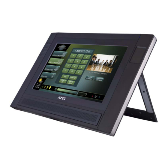
Available in black (FG5967-01) and white (FG5967-02), the MVP-9000i also features a capacitive touch directional pad, 4 programmable buttons, and over 3 GB of usable flash memory. The MVP-9000i also supports 5 hours of continuous use to three days of standby time. The MVP-9000i is certified compatible with Cisco Compatible Extensions (CCX), Version 4. - Page 16 Introduction The MVP-9000i comes with an integrated rear “kickstand”, allowing it to be used and displayed away from a Docking Station (FIG. 2). It also comes with a pre-installed 802.11a/b/g wireless card. Stylus Capacitive touch Capacitive touch directional pad buttons (4)
-
Page 17: Mvp-9000I 9" Modero® Viewpoint® Touch Panel With Intercom
Transmit IR (transmit only) over 20 feet (6.10 m) from the panel. • IR emitters on G4 panels share the device address number of the panel. • Transmits AMX fixed frequencies at 38KHz and 455KHz and third-party user-programmable frequencies from 20KHz to 1.5MHz Certifications: •... -
Page 18: Memory
In addition to its speaker, the MVP-9000i also utilizes its mini-USB port as a connector for standard headphones or headsets. These headphones must use a mini-USB plug or adaptor in order to utilize this feature. -
Page 19: Basic Operation
On Mode as soon as it is placed in the Docking Station. Powering on the MVP-9000i The MVP-9000i may be powered on by touching and holding the touchscreen. If the device was in Sleep Mode, it will automatically turn on when put into a Table or Wall Docking Station. -
Page 20: Cleaning The Touch Overlay And Case
Do not directly spray the device: instead, spray the cloth to clean the touch screen overlay. Do NOT use an abrasive of any type to clean the MVP-9000i, as this may permanently damage or remove the device’s finish. MVP-9000i 9" Modero® ViewPoint® Touch Panel with Intercom... -
Page 21: Picture View
With Picture View, inserting a microSD memory card into the slot on the left side of the device, or connecting a USB drive via the mini-USB port (FIG. 2), allows the MVP-9000i to access JPEG images on that card and display them on the touchscreen (FIG. -
Page 22: Preview Mode And Normal Mode
Picture View goes into its Normal Mode when the MVP-9000i goes into idle timeout while connected to a USB drive or memory card. -
Page 23: Seamless Wireless To Wired Swap
Station or Wall Docking Station. To prevent offline events when transitioning between wired and wireless connectivity, the MVP-9000i allows for seamless swapping. For swapping to work correctly, the Wired (page 65) and WiFi (page 66) network settings must be configured properly. The current connection mode to the master is indicated by the connection icon in the upper right hand corner of the setup pages as well as in the Current Connection field in the System Settings page under the Master tab. - Page 24 Introduction FIG. 6 Confirmation Dialog popup window for undocking MVP-9000i 9" Modero® ViewPoint® Touch Panel with Intercom...
-
Page 25: Accessories
Ethernet connection when the panel is docked. The MVP-TDS-9's sleek design allows the panel to slide into perfect placement in the docking station and includes password protection support for panel removal. When the MVP-9000i is placed into the PoE docking station, it automatically switches from wireless to wired Ethernet communication. The Docking Station is available in either black (MVP-TDS-9-GB, FG5967-10) or white (MVP-TDS-9-GW, FG5967-11). -
Page 26: Powering The Mvp-Tds-9
If necessary, the cable may be spliced and shortened for special installations. For both Ethernet connection and for power for the MVP-9000i, the MVP-TDS-9 uses a special Ethernet cable (FIG. 8) in order to connect to the PS-POE-AT. -
Page 27: Recharging
Recharging To recharge the MVP-9000i, slide the device into the Table Docking Station cradle bottom-first and make sure the device is fully seated in the Docking Station. The charger pins in the bottom of the cradle (FIG. 9) must be in contact with the connector on the bottom of the MVP-9000i for it to start recharging. -
Page 28: Wall Docking Station
Accessories Wall Docking Station While charging the MVP-9000i, the Power-over-Ethernet MVP-WDS-9 Wall/Flush Mount Docking Station provides fast, reliable wired Ethernet communication to the touch panel. In addition, the MVP-WDS-9 employs a unique, anti- theft locking mechanism to keep the touch panel safe and secure. With a push of a button, the panel glides forward for simple removal and transport. -
Page 29: Unlocking The Touch Panel
Security Release button on the front of the device in emergencies. The station ejects the device top first. The device uses two neodymium rare-earth magnets to keep the MVP-9000i from falling out of its cradle when the touch panel is angled forward. -
Page 30: Recharging
Inserting the MVP-9000i into the MVP-WDS-9 Press the top of the MVP-9000i back until it clicks. The touch panel is now locked into the Docking Station, and the station will automatically charge the device’s battery. (Please refer to the Power Management Page section on page 47 to check on the battery charge status.) -
Page 31: A Note About Wall And Rack Installation
FIG. 13 shows an AMX device installed in a wall with a filled volume (such as with insulation or concrete), as well as with a closed volume (such as between studs in an otherwise finished wall). The diagram shows how heat generated by the device or other devices may have no way to escape, and may build up to levels that may affect device operation. -
Page 32: Installing The Mvp-Wds-9
Since the Wall Docking Station is intended to be affixed to a wall or other permanent structure, care must be taken to ensure its proper installation to prevent potential damage to the MVP-9000i placed within. Other than wall installation tools, the only tool required for this installation is a #2 Phillips screwdriver. - Page 33 Ethernet Port (FIG. 16). Recommended Ethernet installation Recommended USB installation Knockout placement in back box Ethernet port Ferrite installation position Recommended Ethernet cable path FIG. 16 MVP-WDS-9 - Ethernet cable path MVP-9000i 9" Modero® ViewPoint® Touch Panel with Intercom...
-
Page 34: Installing The Optional Metal Rough-In Box
Wall Docking Station. The neodymium magnets will hold it in place. To remove the MVP-9000i, unlock the touch panel (see the Unlocking the Touch Panel section on page 15 for more information) and wait for the touch panel to pull away from the Wall Docking Station. Once it has been released, grip it by the top of the device, and pull it free from the Docking Station. -
Page 35: Other Mvp-Wds-9 Installations
To avoid this, the box may be installed with adhesive. Test an unobtrusive spot on the back of the box with a sample of the adhesive to check for any adverse reactions before installing the device. MVP-9000i 9" Modero® ViewPoint® Touch Panel with Intercom... -
Page 36: Undocking From The Mvp-Tds-9 Or Mvp-Wds-9
Press the Release button (see FIG. 7 for the Table Docking Station or FIG. 11 for the Wall Docking Station). A password keypad will pop up on the MVP-9000i screen. Enter a password in the password keypad and press Enter. - Page 37 FIG. 20 Ejected position for the MVP-9000i Remove the device. The device will remain in the ejected position in the MVP-WDS-9 until the MVP-9000i is removed. Wait until the MVP-WDS-9’s ejection door has completely withdrawn before re-installing the MVP- 9000i.
- Page 38 Accessories MVP-9000i 9" Modero® ViewPoint® Touch Panel with Intercom...
-
Page 39: Configuring Communication
Studio and TPDesign4 programs. In the example below (FIG. 21), three MVP-9000i devices are shown at varying distances from an AP gateway. As with any other AP network, the gateway is spaced so as to allow a maximum wireless coverage for the three devices. -
Page 40: Ir Communication
In certain situations, the MVP-9000i may be used as an infrared remote device for other AMX controllers. The device can transmit IR over 20 feet (6.10 m) from the panel at AMX frequencies of 38KHz and 455KHz, and third-party device frequencies between 20KHz and 120KHz. -
Page 41: Setting The Panel's Device Number
Because this can result in connection loss while the network is moving to the new frequency, AMX has restricted the 5GHz operation at this time to only those channels that are allowed without supporting DFS. - Page 42 2.472 GHz 2.472 GHz 2.472 GHz 2.472 GHz Channel 14: 2.484 GHz Europe includes those countries adhering to ETSI standard EN 301 893 V1.5.1, the European Union's harmonized radio standard for unlicensed devices. MVP-9000i 9" Modero® ViewPoint® Touch Panel with Intercom...
-
Page 43: Configuring Wireless Network Access
Configuring Wireless Network Access The first step in connecting the MVP-9000i to a wireless network is to configure the wireless communication parameters within the device’s System Settings page. This is done via the System Settings page, which allows configuration of the IP Address, System Number and Username/Password information assigned to the target Master. -
Page 44: Wireless Communication Using A Static Ip Address
Signal - Displays the signal strength MAC Address - Unique identification of the transmitting Access Point FIG. 27 Wireless Site Survey page While running a site survey, wireless connectivity will be unavailable. MVP-9000i 9" Modero® ViewPoint® Touch Panel with Intercom... - Page 45 Simple Mode popup window (FIG. 28). For any other security mode, clicking Connect will open the Enterprise Mode popup window (FIG. 29). Different EAP methods are selectable from the Security Type button. FIG. 28 Wireless Security: Simple Mode popup window FIG. 29 Wireless Security: Enterprise Mode popup window MVP-9000i 9" Modero® ViewPoint® Touch Panel with Intercom...
-
Page 46: Step 2: Configure The Card's Wireless Security Settings
Step 3: Choose a Master Connection Mode The MVP-9000i requires a decision on the type of connection to be made between it and the Master. To establish a Master connection: From the System Settings page, select the Master tab if it is not already selected. -
Page 47: Ethernet Over Usb
Ethernet Over USB The MVP-9000i device supports an Ethernet over USB driver for panel downloads and firmware updates. This means that the device can connect to a host computer for updates through its Mini USB port instead of through a standard Ethernet port (FIG. - Page 48 USB interface on the PC must be 172.16.0.xx. Ensure that it is in the same subnet as the IP address given to the usb0 interface on the MVP-9000i, but make sure that it has a different node number. The IP address cannot be the same as the panel`s USB IP address.
-
Page 49: Configure A Virtual Netlinx Master Using Netlinx Studio
Windows side. Usually, this IP address is a random value and in a totally different subnet. The user may set the Windows network properties for the Ethernet over USB interface to have a specific address whenever the Windows XP system detects an MVP-9000i with an assigned IP address. In Windows XP: From the Windows XP desktop, click on Start >... - Page 50 The System Connection status button turns green after a few seconds to indicate an active USB connection to the PC via the Virtual Master. If the System Connection icon does not turn green, check the USB connection and communication settings and refresh the system. MVP-9000i 9" Modero® ViewPoint® Touch Panel with Intercom...
-
Page 51: Ethernet
Click the Communications Settings button to open the Communications Settings dialog (FIG. 41). Click on the Virtual NetLinx Master radio button (from the Platform Selection section) to indicate that you are working as a NetLinx Master. MVP-9000i 9" Modero® ViewPoint® Touch Panel with Intercom... - Page 52 Enter the IP Address information of the PC used as a Virtual Master. FIG. 43 Sample System Settings page (for Virtual Master communication) MVP-9000i 9" Modero® ViewPoint® Touch Panel with Intercom...
-
Page 53: Using G4 Web Control To Interact With A G4 Panel
Verify your NetLinx Master (ME260/64 or NI-Series) has been installed with the latest firmware KIT file from www.amx.com. Refer to the NetLinx Master instruction manual for more detailed information on the use of the new Web-based NetLinx Security. -
Page 54: Using The Netlinx Master To Control The G4 Panel
Both HTTP and HTTPS Ports are enabled by default via the Manage System > Server page. If the Master has been previously configured for secured communication, click OK to accept the AMX SSL certificate, if SSL is enabled, and then enter a valid username and password into the fields within the Login dialog. - Page 55 A small circle appears within the on-screen G4 panel page and corresponds to the location of the mouse cursor. A left-mouse click on the computer-displayed panel page equates to an actual touch on the target G4 panel page. MVP-9000i 9" Modero® ViewPoint® Touch Panel with Intercom...
- Page 56 Configuring Communication MVP-9000i 9" Modero® ViewPoint® Touch Panel with Intercom...
-
Page 57: Setup Pages
Setup Pages Setup Pages Overview The MVP-9000i features on-board Setup pages. Use the options in the Setup pages to access panel information and make various configuration changes. Accessing the Setup pages To access the Setup pages, hold the bottom left capacitive touch button and the bottom of the directional pad (FIG. 1) for 3 seconds. -
Page 58: Navigation Buttons
Time: this button opens the Date/Time page (page 52) Panel Info: this button opens the Panel Information page (page 54) Protected: this button opens the Protected Setup page (page 59) MVP-9000i 9" Modero® ViewPoint® Touch Panel with Intercom... -
Page 59: Display Page
This switch controls the flyout menus on the capacitive touch buttons on the left of the screen. “On” allows use of any flyout menus connected to the buttons, and “OFF” disables them. MVP-9000i 9" Modero® ViewPoint® Touch Panel with Intercom... -
Page 60: Audio Page
Down buttons to adjust the volume level in one-percent increments (range = 0 - 100%). • The Mute On button toggles the Mute feature. Press it again to switch it to Mute Off. MVP-9000i 9" Modero® ViewPoint® Touch Panel with Intercom... -
Page 61: Wav Files - Supported Sample Rates
Setup Pages WAV files - Supported Sample Rates The following sample rates for WAV files are supported by MVP-9000i panels: Supported WAV Sample Rates • 48000 Hz • 16000 Hz • 44100 Hz • 12000 Hz • 32000 Hz • 11025 Hz •... -
Page 62: Battery Conditioning
Test button on the Power Management page.If any fault exists in the battery, a confirmation dialog box appears (FIG. 54) that warns of the fault. For more information on the fault, please contact AMX Customer Support, and give the fault code from the confirmation dialog. -
Page 63: Automatic Battery Conditioning
Max Lifetime: The battery conditioning cycle favors the maximum total operational lifetime of the battery. Favoring the maximum battery lifetime may affect the battery’s maximum run time between chargings. For more information on the MVP-9000i’s battery lifetime and battery replacement procedures, please refer to the Battery Life and Replacement section on page 163. -
Page 64: Testing The Battery
Setup Pages Testing the Battery The Test button on the Power Management page allows you to verify that the MVP-9000i’s battery is functioning properly and does not require reconditioning. If the battery requires reconditioning, the Test function will walk you through the procedures necessary to start it. - Page 65 The Display Brightness should set to 90% or higher so the battery will discharge as fast as possible. If you undock the MVP-9000i from its Docking Station while the panel is in the reconditioning process, a popup window appears reading "Battery maintenance is paused." (page 51). This popup window will close when the touch panel is redocked within the Docking Station.
-
Page 66: Date/Time Page
If the panel is not connected to a Master, the Get Time function will not work. To set the date and time manually on an MVP-9000i: From the Date/Time page, press the Set Time button to open the Set Date/Time popup window (FIG. 61). - Page 67 Set Date/Time popup window Set Date/Time Popup Window Set Date/Time: Use the Up/Down arrow buttons to adjust the MVP-9000i’s calendar date and time. A white outline around the field indicates which field is currently selected. • Year range = 2000 - 2199 •...
-
Page 68: Panel Information Page
Panel Start Time: Displays the time taken by the panel to wake up from sleep mode. Screen Width: Displays the screen width (in pixels). MVP-9000i = 800 pixels. Screen Height: Displays the screen height (in pixels). MVP-9000i = 480 pixels. -
Page 69: Panel Information Page - Config
Displays the battery level (level count) value for the panel. Battery Port: Displays the battery port (port count) value for the panel. Power Up Page: Displays the page assigned to display after the panel is powered-up. MVP-9000i 9" Modero® ViewPoint® Touch Panel with Intercom... -
Page 70: Panel Information Page - File
Displays the last revision date for the project. Build Number Displays the build number information of the TPD4 software used to create the project file. Blink Rate: Displays the feedback blink rate, in 5-second increments. MVP-9000i 9" Modero® ViewPoint® Touch Panel with Intercom... -
Page 71: Panel Information Page - Project
Receivers tab). • For example, if you set the AMX IR 38K Port to 7 and then put a button on the panel with a channel code of 5 and a port of 7, it will trigger the IR code in slot 5 of the AMX IR 38K Port. - Page 72 Setup Pages MVP-9000i 9" Modero® ViewPoint® Touch Panel with Intercom...
-
Page 73: Protected Setup Pages
Opens a keypad used to view or change the device number of the panel. Device Name Opens a keypad used to view or change the device name used for the panel. Options: Opens the System & Panel Options page (page 60). MVP-9000i 9" Modero® ViewPoint® Touch Panel with Intercom... -
Page 74: System & Panel Options Page
Table Dock Latch: • Enables and disables the docking latch on the Table Docking Station (page 11). If User Access is Enabled in the Passwords page (page 84), this switch will be greyed out. MVP-9000i 9" Modero® ViewPoint® Touch Panel with Intercom... -
Page 75: Function Show Example
Remove Pages: • Removes all TPD4 touch panel pages currently on the panel, including the pre-installed AMX Demo pages. This option invokes a Confirmation dialog, prompting you to confirm your selection before removing the panel pages. • Note that the YES button on the Confirmation dialog is disabled for 5 seconds as additional protection against accidentally resetting the panel or removing the panel pages. -
Page 76: Security Settings
For more information on configuring AMX devices for a secure environment, please refer to the guide Security Profiles: Configuring AMX Devices For Installation Into a Secure Environment, available at www.amx.com. -
Page 77: Installing Firmware
Firmware Installation popup window If the MVP-9000i needs to be returned to its factory default firmware, press the Factory button. If you have already installed the latest available firmware version and wish to reinstall a previous version, press the Previous button. If you wish to install new firmware from a connected microSD card or external USB stick, press the New button. -
Page 78: System Settings Page
(into each field) assigned to a pre-configured user profile on the Master. This profile should have the pre-defined level of access/configuration rights. NDP Name: Displays the name of the device connecting to the Master. MVP-9000i 9" Modero® ViewPoint® Touch Panel with Intercom... -
Page 79: System Settings - Wired
DHCP setting for the wired interface is highly recommended. Configuring a static IP address on the Wired Settings page without network connectivity may lead to a loss of connection. MVP-9000i 9" Modero® ViewPoint® Touch Panel with Intercom... -
Page 80: System Settings - Wifi
This is a domain name to the panel for DNS look-up. MAC Address: This unique address identifies the wireless Ethernet card in the panel (read- only). Next: Touch this button to move to the second page of the WiFi tab (page 67) MVP-9000i 9" Modero® ViewPoint® Touch Panel with Intercom... - Page 81 This indicator displays a description of the signal strength of the Access Point signal. Signal Level: Provides a graphical representation of the Signal Level Value. Prev. Touch this button to return to the first page of the WiFi tab. MVP-9000i 9" Modero® ViewPoint® Touch Panel with Intercom...
-
Page 82: Security Modes
(FIG. 77) offers EAP-LEAP (page 72), EAP-FAST (page 74), EAP-PEAP (page 76), EAP-TTLS (page 77), and EAP-TLS (page 79). FIG. 76 Wireless Security: Simple Mode popup window FIG. 77 Wireless Security: Enterprise Mode popup window MVP-9000i 9" Modero® ViewPoint® Touch Panel with Intercom... -
Page 83: Open
WEP security requires that both a target AP be identified and an encryption method be implemented prior to establishing communication. In addition to providing Open Authentication capabilities, this page also supports Hexadecimal and ASCII keys. MVP-9000i 9" Modero® ViewPoint® Touch Panel with Intercom... - Page 84 Refer to the Configuring Wireless Network Access section on page 29 and the Using the Wireless Site Survey Tool section on page 30 for further details on these security options. MVP-9000i 9" Modero® ViewPoint® Touch Panel with Intercom...
-
Page 85: Wpa-Psk
Refer to the Configuring Wireless Network Access section on page 29 for details on these security options. Refer to the Using the Wireless Site Survey Tool section on page 30 for more information on using this tool. MVP-9000i 9" Modero® ViewPoint® Touch Panel with Intercom... -
Page 86: Eap Security & Server Certificates - Overview
The configuration fields described below take variable length strings as inputs. An on-screen keyboard is opened when these fields are selected. LEAP (Lightweight Extensible Authentication Protocol) was developed to transmit authentication information securely in a wireless network environment. MVP-9000i 9" Modero® ViewPoint® Touch Panel with Intercom... - Page 87 This works in tandem with the Password string which is similar to the password entered to gain access to a secured workstation. Typically, this is in the form of a username such as jdoe@amx.com. Password: Opens an on-screen keyboard. Enter the network password string specified...
-
Page 88: Eap-Fast
This works in tandem with the Password string which is similar to the password entered to gain access to a secured workstation. Typically, this is in the form of a username such as: jdoe@amx.com. MVP-9000i 9" Modero® ViewPoint® Touch Panel with Intercom... - Page 89 • Save - store the new security information, apply changes, and return to the previous page. Refer to the EAP Authentication section on page 178 and the Using the Wireless Site Survey Tool section on page 30 for further details on these security options. MVP-9000i 9" Modero® ViewPoint® Touch Panel with Intercom...
-
Page 90: Eap-Peap
This works in tandem with the Password string, which is similar to the password entered to gain access to a secured workstation. Typically, this is in the form of a username such as jdoe@amx.com. Password: Opens an on-screen keyboard to enter the network password string specified... -
Page 91: Eap-Ttls
Setup is similar to PEAP, but differs in the following areas: An anonymous identity must be specified until the secure tunnel between the panel and the Radius server is setup to transfer the real identity of the user. MVP-9000i 9" Modero® ViewPoint® Touch Panel with Intercom... - Page 92 This works in tandem with the Password string which is similar to the password entered to gain access to a secured workstation. Typically, this is in the form of a username such as: jdoe@amx.com. Anonymous Identity: Opens an on-screen keyboard. Enter an IT provided alpha-numeric string which (similar to the username) used as the identity, but that does not represent a real user.
-
Page 93: Eap-Tls
EAP-TLS security is designed for wireless environments where it is necessary to securely transmit data over a wireless network by adding an additional level of security protocol via the use of a private key. MVP-9000i 9" Modero® ViewPoint® Touch Panel with Intercom... - Page 94 This works in tandem with the Password string, which is similar to the password entered to gain access to a secured workstation. Typically, this is in the form of a username such as: jdoe@amx.com. Certificate Authority: When pressed, the panel displays an on-screen Certificate Authority (CA) File Location keyboard, for entering the name of the certificate authority file which is used to validate the server certificate.
-
Page 95: Client Certificate Configuration
Certificate Types Supported by the Modero Firmware Configuration Field Name Certificate File Type Supported Certificate Authority field PEM and DER Client Certificate field PEM and DER Private Key field .PEM, DER, and PKCS12 MVP-9000i 9" Modero® ViewPoint® Touch Panel with Intercom... -
Page 96: System Settings - Usb
Protected Setup Pages System Settings - USB The USB tab (FIG. 88) controls the ability for the MVP-9000i to connect to a network via a USB connection. FIG. 88 System Settings page - USB tab The features on the USB tab include:... -
Page 97: G4 Web Control Settings Page
NetLinx Security browser window. Control Password: Use this field to enter the G4 Authentication session password required for VNC access to the panel. This password is limited to between 1 and 8 characters. MVP-9000i 9" Modero® ViewPoint® Touch Panel with Intercom... -
Page 98: Passwords
• The PASSWORD 1, 2, 3, 4 and 5 (protected) buttons open a keyboard to enter alphanumeric values associated to the selected password group. Note: Clearing Password #5 removes the need to enter a password before accessing the Protected Setup page. MVP-9000i 9" Modero® ViewPoint® Touch Panel with Intercom... - Page 99 Enter the new password into the Password keyboard and press Done. To send undocking reports to the Master: From the Password Settings page, press the Report button to enable it. The MVP-9000i will send a report to the Master of undockings in the form of an “undock-<user>” string.
-
Page 100: Panel Logs Page
Protected Setup Pages For more information on removing an MVP-9000i from a MVP-WDS-9 Docking Station, please refer to the Unlocking the Touch Panel on page 15. Panel Logs Page The Panel Logs page (FIG. 92) chronicles all previous connections between the device and the network FIG. - Page 101 2 days, 5 days, and "NEVER". Clear Cache: Clears the contents of both the RAM and Flash caches. On/Off: Saves any changes made to the Flash Cache Size or Cache Expires fields. MVP-9000i 9" Modero® ViewPoint® Touch Panel with Intercom...
-
Page 102: Panel Statistics Page
Lists the number of ICSP messages processed within the previous 15 minutes. Dropped: Lists the number of ICSP messages dropped within the previous 15 minutes. Clear: Clears all fields on the ICSP tab. Refresh: Refreshes all data on the ICSP tab. MVP-9000i 9" Modero® ViewPoint® Touch Panel with Intercom... -
Page 103: Panel Statistics - Blinks Tab
Panel Statistics - IP Tab The IP tab (FIG. 96) displays received and transmitted IP packets. Touch the Refresh button to refresh the page with its current values. FIG. 96 Panel Statistics - IP Tab MVP-9000i 9" Modero® ViewPoint® Touch Panel with Intercom... -
Page 104: Panel Statistics - Wireless Tab
Panel Statistics - Wireless Tab The Wireless tab (FIG. 96) displays the MVP-9000i’s wireless access statistics, including the wireless mode, the frequency used, and the latest used access point. Touch the Refresh button to return the counters to their placement before the latest update. -
Page 105: Sip Settings Page
Port Number: The option displays the port you use to connect to the proxy server. The standard SIP port is 5060, but some providers use different ports. MVP-9000i 9" Modero® ViewPoint® Touch Panel with Intercom... - Page 106 Touch the Cancel button to return to the Protected Setup page without saving any changes made on the SIP Settings page. Touch the Save button to save the changes and return to the Protected Setup page. MVP-9000i 9" Modero® ViewPoint® Touch Panel with Intercom...
-
Page 107: Upgrading Firmware
MVP-9000i, and then connect the USB stick to the female USB port. If using a microSD card, insert the card into the slot on the left of the device. Turn on the MVP-9000i and allow it to boot up. For best results, connect the panel to its power source or place it in a Table or Wall Docking Station. - Page 108 Upgrading Firmware If the panel boots up and detects a KIT file in the “MVP-9000i” directory on the microSD card or USB stick, the panel will request that you press the screen to upgrade or wait to continue booting (FIG. 101). Touch the screen to start the firmware update process.
-
Page 109: Upgrading From Previous Firmware
Upgrading Firmware Upgrading from Previous Firmware The MVP-9000i allows the option to revert the device to the previous firmware run before an upgrade. To upgrade the device from previously loaded firmware: From the Protected Setup page, press the Options button to open the System & Panel Options page. - Page 110 Virtual NetLinx Master Settings Within this dialog, enter the Master System number. The default is 1. In the Available Connections section, click on the IP address for the touch panel to select it. MVP-9000i 9" Modero® ViewPoint® Touch Panel with Intercom...
-
Page 111: Step 3: Confirm And Upgrade The Firmware Via The Usb Port
OnLine Tree tab of the Workspace window. Virtual Master firmware version and device number MVP panel firmware version and device number FIG. 109 NetLinx Workspace window (showing panel connection via a Virtual NetLinx Master) MVP-9000i 9" Modero® ViewPoint® Touch Panel with Intercom... - Page 112 In some cases, several Kit files may be included in a .zip file; extract the .zip file to access the required Kit file. If the panel firmware version is not the latest available; locate the latest firmware file from the www.amx.com > Tech Center > Firmware Files > Modero Panels section of the website.
-
Page 113: A Special Note For Network Interface Connections
PC’s network switches as the PC’s source address. In some cases, network administrators will notice the NIC connection and reconfigure any PC that has connected to the MVP-9000i. Business, college, and government installations are the type of installations that would be most affected, and most home installations would not be affected. - Page 114 (FIG. 115). FIG. 115 Bindings for Local area list detail When finished, click OK to close the Advanced Settings window and save all changes. MVP-9000i 9" Modero® ViewPoint® Touch Panel with Intercom...
-
Page 115: Reverting The Mvp-9000I To Factory Default Firmware
Reverting the MVP-9000i to Factory Default Firmware In certain circumstances, it may be necessary to return the MVP-9000i to its original factory firmware and settings. To do so, the procedure may be started either from the touch screen during rebooting, or by accessing the Protected Setup pages. - Page 116 Firmware Installation popup window. FIG. 118 Factory Firmware reset confirmation dialog box If you choose Yes, the device will retrieve the files and then reboot (FIG. 119). FIG. 119 Factory Firmware Reset system message MVP-9000i 9" Modero® ViewPoint® Touch Panel with Intercom...
-
Page 117: Programming
Programming Overview You can program the MVP-9000i, using the commands in this section, to perform a wide variety of operations using Send Commands and variable text commands. A device must first be defined in the NetLinx programming language with values for the Device: Port: System (in all programming examples - Panel is used in place of these values and represents all Modero panels). -
Page 118: Afp
The custom event, however, is always transmitted. The following seven gesture types are supported: Swipe up Swipe down Swipe right Swipe left MVP-9000i 9" Modero® ViewPoint® Touch Panel with Intercom... -
Page 119: Gesture Velocity
Whenever a gesture is recognized and processed a custom event is also sent to the master. The following values describe this event: CUSTOM_EVENT ADDRESS is 1 CUSTOM_EVENT EVENTID is 600 Custom.Value1 is the gesture number Custom.Value2 is the simplified gesture velocity Custom.Value3 is the precise gesture velocity Gesture numbers are: MVP-9000i 9" Modero® ViewPoint® Touch Panel with Intercom... -
Page 120: Enabling Or Disabling The Gesture Custom Event
NOTE: This setting is not retained and the default is to always send the events. To enable master whenever sending the event, the value after the dash can be "on", "ON", or “1”. Anything else will a gesture is disable sending custom events. detected. MVP-9000i 9" Modero® ViewPoint® Touch Panel with Intercom... -
Page 121: Page Commands
= 1 - 50 ASCII characters. Name of the page the popup is displayed named hide effect. hide effect name = Refers to the popup effect names being used. Example: SEND_COMMAND Panel,"'@PHE-Popup1;Slide to Left'" Sets the Popup1 hide effect name to ’Slide to Left’. MVP-9000i 9" Modero® ViewPoint® Touch Panel with Intercom... -
Page 122: Php
= 1 - 50 ASCII characters. Name of the page the popup is displayed On. Example: SEND_COMMAND Panel,"'@PPF-Popup1;Main'" Example 2: SEND_COMMAND Panel,"'@PPF-Popup1'" Deactivates the popup page ’Popup1’ on the current page. MVP-9000i 9" Modero® ViewPoint® Touch Panel with Intercom... -
Page 123: Ppg
= 1 - 50 ASCII characters. Name of the page the popup is displayed On. Example: SEND_COMMAND Panel,"'@PPN-Popup1;Main'" Activates ’Popup1’ on the ’Main’ page. Example 2: SEND_COMMAND Panel,"'@PPN-Popup1'" Activates the popup page ’Popup1’ on the current page. MVP-9000i 9" Modero® ViewPoint® Touch Panel with Intercom... -
Page 124: Ppt
Flip to a specified Syntax: page. "'PAGE-<page name>'" Variable: page name = 1 - 50 ASCII characters. Name of the page the popup is displayed On. Example: SEND_COMMAND Panel,"'PAGE-Page1'" Flips to page1. MVP-9000i 9" Modero® ViewPoint® Touch Panel with Intercom... -
Page 125: Ppof
= 1 - 50 ASCII characters. Name of the page the popup is displayed On. Example: SEND_COMMAND Panel,"'PPON-Popup1; Main'" Activates the popup page ’Popup1’ on the Main page. Example 2: SEND_COMMAND Panel,"'PPON-Popup1'" Activates the popup page ’Popup1’ on the current page. MVP-9000i 9" Modero® ViewPoint® Touch Panel with Intercom... -
Page 126: Programming Numbers
Light Mint Mint Medium Mint Dark Mint Very Dark Mint Very Light Cyan Light Cyan Cyan Medium Cyan Dark Cyan Very Dark Cyan Very Light Aqua Light Aqua Aqua Medium Aqua Dark Aqua MVP-9000i 9" Modero® ViewPoint® Touch Panel with Intercom... - Page 127 Very Dark Magenta Very Light Pink Light Pink Pink Medium Pink Dark Pink Very Dark Pink White Grey1 Grey3 Grey5 Grey7 Grey9 Grey4 Grey6 Grey8 Grey10 Grey12 Grey13 Grey2 Grey11 Grey14 Black TRANSPARENT MVP-9000i 9" Modero® ViewPoint® Touch Panel with Intercom...
-
Page 128: Font Styles And Id Numbers
Bevel -L Cursor Left Bevel -M Cursor Left with Hole Bevel -S Cursor Right Circle 15 Cursor Right with Hole Circle 25 Custom Frame Circle 35 Diamond 15 Circle 45 Diamond 25 MVP-9000i 9" Modero® ViewPoint® Touch Panel with Intercom... - Page 129 Menu Bottom Rounded 105 Menu Right Rounded 165 Menu Bottom Rounded 115 Menu Right Rounded 175 Menu Bottom Rounded 125 Menu Right Rounded 185 Menu Bottom Rounded 135 Menu Right Rounded 195 MVP-9000i 9" Modero® ViewPoint® Touch Panel with Intercom...
-
Page 130: Button Commands
ClearA[ll] - Clear all popup pages from all pages page name = 1 - 50 ASCII characters. Example: SEND COMMAND Panel,"'^APF-400,Stan,Main Page'" Assigns a button to a standard page flip with page name 'Main Page'. MVP-9000i 9" Modero® ViewPoint® Touch Panel with Intercom... -
Page 131: Bat
Sets the Off state border color to 12 (Yellow). Colors can be set by Color Numbers, Color name, R,G,B,alpha colors (RRGGBBAA) and R, G & B colors values (RRGGBB). Refer to the RGB Values for all 88 Basic Colors table on page 112. MVP-9000i 9" Modero® ViewPoint® Touch Panel with Intercom... -
Page 132: Bcf
Sets the button’s variable text 530 ON/OFF state draw order (from bottom to top) to Border, Fill, Text, Icon, and Image. Example 2: SEND_COMMAND Panel,"'^BDO-1,0,12345'" Sets all states of a button back to its default drawing order. MVP-9000i 9" Modero® ViewPoint® Touch Panel with Intercom... -
Page 133: Bfb
1 = Off state and 2 = On state). number of lines = 0 - 240. Example: SEND_COMMAND Panel,"'^BLN-500,55'" Equally removes 55 lines from the top and 55 lines from the bottom of the video button. MVP-9000i 9" Modero® ViewPoint® Touch Panel with Intercom... -
Page 134: Bmc
Copies the OFF state border, font, Text, bitmap, icon, fill color and text color of the button with a variable text address of 315 onto the OFF state border, font, Text, bitmap, icon, fill color and text color of the button with a variable text address of 150. MVP-9000i 9" Modero® ViewPoint® Touch Panel with Intercom... -
Page 135: Bmf
’%GH<bargraph hi>’ = Set the bargraph upper limit. ’%GL<bargraph low>’ = Set the bargraph lower limit. ’%GN<bargraph slider name>’ = Set the bargraph slider name/Joystick cursor name. ’%GC<bargraph slider color>’ = Set the bargraph slider color/Joystick cursor color. MVP-9000i 9" Modero® ViewPoint® Touch Panel with Intercom... - Page 136 ’%VN<network name>’ = Set network connection name. ’%VP<password>’ = Set the network connection password. Example: SEND_COMMAND Panel,"'^BMF-500,1,%B10%CFRed%CB Blue %CTBlack%Ptest.png'" Sets the button OFF state as well as the Border, Fill Color, Border Color, Text Color, and Bitmap. MVP-9000i 9" Modero® ViewPoint® Touch Panel with Intercom...
-
Page 137: Bmi
1 = Off state and 2 = On state). name of bitmap/picture = 1 - 50 ASCII characters. Example: SEND_COMMAND Panel,"'^BMP-500.504&510.515,1,bitmap.png'" Sets the OFF state picture for the buttons with variable text ranges of 500-504 & 510-515. MVP-9000i 9" Modero® ViewPoint® Touch Panel with Intercom... -
Page 138: Bnc
= 0 (invisible) - 255 (opaque). Example: SEND_COMMAND Panel,"'^BOP-500.504&510.515,1,200'" Example 2: SEND_COMMAND Panel,"'^BOP-500.504&510.515,1,#C8'" Both examples set the opacity of the buttons with the variable text range of 500-504 and 510-515 to 200. MVP-9000i 9" Modero® ViewPoint® Touch Panel with Intercom... -
Page 139: Bor
Sets the border by number (#10) to those buttons with the variable text range of 500-504 & 510-515. SEND_COMMAND Panel,"'^BOR-500.504&510,AMX Elite -M'" Sets the border by name (AMX Elite) to those buttons with the variable text range of 500-504 & 510-515. The border style is available through the TPDesign4 border-style drop-down list. Refer to theTPD4 Border Styles by Name table on page 114 for more information. -
Page 140: Bsf
Variable: control variable text address range = 1 - 4000. connection. connection = 0 (Log-Off connection) and 1 (Log-On connection). Example: SEND_COMMAND Panel,"'^BVL-500,0'" Logs-off the computer control connection of the button. MVP-9000i 9" Modero® ViewPoint® Touch Panel with Intercom... -
Page 141: Bvn
^DLD Syntax: Set the disable "'^DLD-<status>'" cradle LED flag. Variable: status = (0= cradle operates normally, 1= forces the cradle LEDs to always be dim). Example: SEND_COMMAND Panel,"'^DLD-1'" Disables the cradle LEDs. MVP-9000i 9" Modero® ViewPoint® Touch Panel with Intercom... -
Page 142: Dpf
Sets the font size to font ID #4 for the On and Off states of buttons with the variable text range of 500-504 & 510-515. The Font ID is generated by TPD4 and is located in TPD4 through the Main menu. Panel > Generate Programmer's Report >Text Only Format >Readme.txt. MVP-9000i 9" Modero® ViewPoint® Touch Panel with Intercom... -
Page 143: Gdi
= 1 - 4000. in 1/10th of a bargraph ramp down time = In 1/10th of a second intervals. second. Example: SEND_COMMAND Panel,"'^GRD-500,200'" Changes the bargraph ramp down time to 20 seconds. MVP-9000i 9" Modero® ViewPoint® Touch Panel with Intercom... -
Page 144: Gru
= 0 - 9900 ( a value of 0 is clear ). Example: SEND_COMMAND Panel,"'^ICO-500.504&510.515,1&2,1'" Sets the icon for On and Off states for buttons with variable text ranges of 500-504 & 510-515. MVP-9000i 9" Modero® ViewPoint® Touch Panel with Intercom... -
Page 145: Irm
Zero can be used for an absolute position Example: SEND_COMMAND Panel,"'^JSI-500.504&510.515,1&2,1'" Sets the Off/On state icon alignment to upper left corner for those buttons with variable text range of 500-504 & 510-515. MVP-9000i 9" Modero® ViewPoint® Touch Panel with Intercom... -
Page 146: Jst
Variable: variable text variable text address range = 1 - 4000. range. command value = (0= hide, 1= show). Example: SEND_COMMAND Panel,"'^SHO-500.504&510.515,0'" Hides buttons with variable text address range 500-504 & 510-515. MVP-9000i 9" Modero® ViewPoint® Touch Panel with Intercom... -
Page 147: Tec
1 = Off state and 2 = On state). new text = 1 - 50 ASCII characters. Example: SEND_COMMAND Panel,"'^TXT-500.504&510.515,1&2,Test Only'" Sets the On and Off state text for buttons with the variable text ranges of 500-504 & 510-515. MVP-9000i 9" Modero® ViewPoint® Touch Panel with Intercom... -
Page 148: Uni
5 - En/Disable Blink Enable LED blinking 6 - En/Disable Fade Transitions from high/low are smooth 7 - Set Color Set the tri-color (MVP9000i) LED to one of the supported NetLinx colors (Yellow, Orange, VeryLightCyan, etc…) MVP-9000i 9" Modero® ViewPoint® Touch Panel with Intercom... -
Page 149: Miscellaneous Mvp Strings
MVP Panel Lock Passcode Commands These commands are used to maintain a passcode list. With the MVP-9000i, a password must be entered to remove the panel from the Wall Docking Station. Only the passcode is entered. The user entry is just for identifying the passcodes. -
Page 150: Text Effects Names
• Soft Drop Shadow 4 with outline • Soft Drop Shadow 5 with outline • Soft Drop Shadow 6 with outline • Soft Drop Shadow 7 with outline • Soft Drop Shadow 8 with outline MVP-9000i 9" Modero® ViewPoint® Touch Panel with Intercom... -
Page 151: Button Query Commands
(string encode) button text length These fields are populated differently for each query command. The text length (String Encode) field is not used in any command. MVP-9000i 9" Modero® ViewPoint® Touch Panel with Intercom... -
Page 152: Bcb
The result sent to the Master would be: ButtonGet Id = 529 Type = 1012 Flag VALUE1 = 1 VALUE2 = 9 VALUE3 = 0 TEXT = #FF8000FF TEXT LENGTH = 9 MVP-9000i 9" Modero® ViewPoint® Touch Panel with Intercom... -
Page 153: Bct
The result sent to the Master would be: ButtonGet Id = 529 Type = 1002 Flag VALUE1 = 1 VALUE2 = 9 VALUE3 = 0 TEXT = Buggs.png TEXT LENGTH = 9 MVP-9000i 9" Modero® ViewPoint® Touch Panel with Intercom... -
Page 154: Bop
The result sent to the Master would be: ButtonGet Id = 529 Type = 1014 Flag VALUE1 = 1 VALUE2 = 22 VALUE3 = 0 TEXT = Double Bevel Raised -L TEXT LENGTH = 22 MVP-9000i 9" Modero® ViewPoint® Touch Panel with Intercom... -
Page 155: Bww
Gets the button 'OFF state' font type index information. The result sent to the Master would be: ButtonGet Id = 529 Type = 1007 Flag VALUE1 = 1 VALUE2 = 72 VALUE3 = 0 TEXT TEXT LENGTH = 0 MVP-9000i 9" Modero® ViewPoint® Touch Panel with Intercom... -
Page 156: Ico
Gets the button 'OFF state' bitmap justification information. The result sent to the Master would be: ButtonGet Id = 529 Type = 1005 Flag VALUE1 = 1 VALUE2 = 5 VALUE3 = 0 TEXT TEXT LENGTH = 0 MVP-9000i 9" Modero® ViewPoint® Touch Panel with Intercom... -
Page 157: Jsi
Gets the button 'OFF state' text justification information. The result sent to the Master would be: ButtonGet Id = 529 Type = 1004 Flag VALUE1 = 1 VALUE2 = 1 VALUE3 = 0 TEXT TEXT LENGTH = 0 MVP-9000i 9" Modero® ViewPoint® Touch Panel with Intercom... -
Page 158: Tec
The result sent to the Master would be: ButtonGet Id = 529 Type = 1008 Flag VALUE1 = 1 VALUE2 = 18 VALUE3 = 0 TEXT = Hard Drop Shadow 3 TEXT LENGTH = 18 MVP-9000i 9" Modero® ViewPoint® Touch Panel with Intercom... -
Page 159: Txt
The result sent to the Master would be: ButtonGet Id = 529 Type = 1001 Flag VALUE1 = 1 VALUE2 = 14 VALUE3 = 1 TEXT = This is a test TEXT LENGTH = 14 MVP-9000i 9" Modero® ViewPoint® Touch Panel with Intercom... -
Page 160: Panel Runtime Operations
AKEYR Remove keyboard or keypad that was displayed using 'AKEYB', 'AKEYP', 'PKEYP', @AKB, @AKP, @PKP, @EKP, or @TKP commands. Remove the Syntax: Keyboard/ Keypad. "'AKEYR'" Example: SEND COMMAND Panel,"'AKEYR'" Removes the Keyboard/Keypad. MVP-9000i 9" Modero® ViewPoint® Touch Panel with Intercom... -
Page 161: Akp
= 1 - 50 ASCII characters. prompt text = 1 - 50 ASCII characters. Example: SEND COMMAND Panel,"'@EKP-33333333;Enter Password'" Pops up the Keypad and initializes the text string '33333333' with prompt text 'Enter Password'. MVP-9000i 9" Modero® ViewPoint® Touch Panel with Intercom... -
Page 162: Pkeyp
Syntax: Play a sound file. "'@SOU-<sound name>'" Variables: sound name = Name of the sound file. Supported sound file formats are: WAV & MP3. Example: SEND COMMAND Panel,"'@SOU-Music.wav'" Plays the 'Music.wav' file. MVP-9000i 9" Modero® ViewPoint® Touch Panel with Intercom... -
Page 163: Tkp
SEND COMMAND Panel,"'@VKB'" Pops-up the virtual keyboard. WAKE Syntax: Force the panel "'WAKE'" out of screen Example: saver mode. SEND COMMAND Panel,"'WAKE'" Forces the panel out of the screen saver mode. MVP-9000i 9" Modero® ViewPoint® Touch Panel with Intercom... -
Page 164: Input Commands
ASCII character set. to the G4 application. Syntax: "'^VKS-<string>'" Variable: string = Only 1 string per command/only one stroke per command. Example: SEND COMMAND Panel,"'^VKS-'8" Sends out the keystroke 'backspace' to the G4 application. MVP-9000i 9" Modero® ViewPoint® Touch Panel with Intercom... -
Page 165: Embedded Codes
Print Screen ($9B) SYSRQ ($9C) ($9D) Windows ($9E) Menu ($9F) Up Arrow ($A0) Down Arrow ($A1) Left Arrow ($A2) Right Arrow ($C0) CTRL key up ($C1) ALT key up ($C2) Shift key up MVP-9000i 9" Modero® ViewPoint® Touch Panel with Intercom... -
Page 166: Panel Setup Commands
"'^PWD-<password level>,<page flip password>'" Variables: password level = 1 - 4. page flip password = 1 - 50 ASCII characters. Example: SEND COMMAND Panel,"'^PWD-1,Main'" Sets the page flip password on Password Level 1 to 'Main'. MVP-9000i 9" Modero® ViewPoint® Touch Panel with Intercom... -
Page 167: Dynamic Image Commands
Note that the %%5F in the file path is actually encoded as %5F . ^RFR Syntax: Force a refresh for "'^RFR-<resource name>'" a given resource. Variable: resource name = 1 - 50 ASCII characters. Example: SEND_COMMAND Panel,"'^RFR-Sports_Image'" Forces a refresh on ’Sports_Image’. MVP-9000i 9" Modero® ViewPoint® Touch Panel with Intercom... -
Page 168: Raf, ^Rmf - Embedded Codes
The number of seconds between refreshes in which the ’%R <refresh 1-65535>’ resource is downloaded again. Refreshing a resource causes the button displaying that resource to refresh also. The default value is 0 (only download the resource once). MVP-9000i 9" Modero® ViewPoint® Touch Panel with Intercom... -
Page 169: Escape Sequences
Current state Address code Address port Channel code Channel port Level code Level port X Resolution of Current button Y Resolution of Current button Name of Button For instance, http://www.amx.com/img.asp?device=$DV would become http://www.amx.com/img.asp?device=10001. MVP-9000i 9" Modero® ViewPoint® Touch Panel with Intercom... -
Page 170: Intercom Commands
SEND_COMMAND TP1, "^ICS-192.168.0.3,9000,9002,0" SEND_COMMAND TP2, "^ICS-192.168.0.4,9002,9000,1" ^ICE' Intercom end. This terminates an intercom call/connection. Syntax: Intercom end. SEND_COMMAND <DEV>,"'^ICE'" Variables: None. Example: SEND_COMMAND TP1,"'^ICE'" SEND_COMMAND TP2,"'^ICE'" Terminates an intercom call between two panels. MVP-9000i 9" Modero® ViewPoint® Touch Panel with Intercom... -
Page 171: Icm-Talk
SEND_COMMAND TP1, "^ICM-MUTEMIC,1" ^ICM- Used to set the speaker level during an intercom call. SPEAKERLEVEL Syntax: Intercom modify SEND_COMMAND <DEV>, "^ICM-SPEAKERLEVEL,55" command. Variables: Valid levels are from 0 to 100. Example: SEND_COMMAND TP1, "^ICM-SPEAKERLEVEL,55" MVP-9000i 9" Modero® ViewPoint® Touch Panel with Intercom... -
Page 172: Sip Commands
= The identifying number of the connection. available state = IDLE, HOLD, or CONNECTED connections used extn = The local extension of this panel (see Example) to manage calls. Example: SEND_COMMAND Panel,"'^PHN-LINESTATE, 1, IDLE, 2, CONNECTED, SIP, <extn>'" MVP-9000i 9" Modero® ViewPoint® Touch Panel with Intercom... -
Page 173: Phn-Answer
Enables (1) or disables (0) the auto-answer feature on the phone. AUTOANSWER Syntax: Enables or "’^PHN-AUTOANSWER, <state>’" disables the Variable: auto-answer state = 0 (Disable) or 1 (Enable) feature of the Example: phone. SEND_COMMAND Panel,"'^PHN-AUTOANSWER, 1'" Enables the auto-answer feature. MVP-9000i 9" Modero® ViewPoint® Touch Panel with Intercom... -
Page 174: Phn-Autoanswer
Enables the privacy feature. ?PHN-PRIVACY The panel responds with the ^PHN-PRIVACY, <state> message. Syntax: Queries the state of the privacy "’?PHN-PRIVACY’" feature. Example: SEND_COMMAND Panel,"'?PHN-PRIVACY'" ^PHN-REDIAL Syntax: Redials the last "’^PHN-REDIAL’" number. Example: SEND_COMMAND Panel,"'^PHN-REDIAL'" MVP-9000i 9" Modero® ViewPoint® Touch Panel with Intercom... -
Page 175: Phn-Setup-Dtmfduration
IP = The IP address for the proxy server proxy server. Example: SEND_COMMAND Panel,"’^PHN-SETUP-PROXYADDR,192.168.223.111’" ^PHN-SETUP- Syntax: STUNADDR "’^PHN-SETUP-STUNADDR,<IP>’" Sets the IP Variable: address for the IP = The IP address for the STUN server STUN server. Example: SEND_COMMAND Panel,"’^PHN-SETUP-STUNADDR,192.168.223.111’" MVP-9000i 9" Modero® ViewPoint® Touch Panel with Intercom... -
Page 176: Phn-Setup-Username
Programming SIP Setup Commands (Cont.) ^PHN-SETUP- Syntax: USERNAME "’^PHN-SETUP-USERNAME,<username>’" Sets the user Variable: name for username = The user name (usually the phone extension) authentication Example: with the proxy SEND_COMMAND Panel,"’^PHN-SETUP-USERNAME,6003’" server. MVP-9000i 9" Modero® ViewPoint® Touch Panel with Intercom... -
Page 177: Battery Life And Replacement
Battery Life and Replacement Overview The battery powering the MVP-9000i is designed for upwards of 300 deep discharge rechargings. Regular shallow rechargings will extensively increase expected battery life, and the device should be stored in either the Table Docking Station or the Wall Docking Station when not in use to keep it at an optimum charge. The battery has reached its effective end of life after it can no longer hold more than a 70 percent charge. -
Page 178: Important Notes
Lithium-Polymer battery can last for as long as five days. However, to maximize usability and minimize the chances of the device becoming completely discharged at a critical moment, the MVP-9000i should be kept in its charging cradle or wall station when not in use. -
Page 179: Proper Battery Maintenance
Proper Battery Maintenance To insure maximum performance and reliability of the MVP-9000i, please insure that a full charge is performed every 3 months if not used regularly. If a battery is left uncharged beyond this time frame, it may result in premature battery lifespan degradation and will require replacement. -
Page 180: Replacing The Battery
Battery Life and Replacement Replacing the Battery Before replacing the battery, download and install the latest firmware for the MVP-9000i. This firmware is available at www.amx.com. IMPORTANT: Prior to battery removal, run the device until the battery is completely discharged. Do NOT discharge the battery before installing the latest MVP-9000i firmware, available at www.amx.com. -
Page 181: Remove The Old Battery
3 screws under label (beneath kickstand) FIG. 123 Placement of screws on the back of the MVP-9000i Two of the screws are at the upper corners of the device, underneath rubber feet that also act as screw covers. Remove the rubber feet to access the screws. - Page 182 Slide the IR emitter cover back into place over the emitter until it clicks. Restart the device to confirm that the new battery is functioning correctly. Please dispose of the old battery in a proper fashion as required by municipal or federal regulations. MVP-9000i 9" Modero® ViewPoint® Touch Panel with Intercom...
-
Page 183: Appendix A: Text Formatting
Example Format Display $A out of $R 32 out of 100 $A of 0 - $R 32 of 0 - 100 $V of $L - $H 532 of 500 - 600 MVP-9000i 9" Modero® ViewPoint® Touch Panel with Intercom... -
Page 184: Text Area Input Masking
- Sets the input mask for the specified addresses. (see the ^BIM section on page 119). • ^BMF subcommand - sets the input mask of a text area (see the ^BMF section on page 121). MVP-9000i 9" Modero® ViewPoint® Touch Panel with Intercom... -
Page 185: Input Mask Ranges
"12" in the previous logical field. If the overflow field already contains a value, the new value will be inserted to the right of the current characters and the overflow field will be MVP-9000i 9" Modero® ViewPoint® Touch Panel with Intercom... -
Page 186: Input Mask Output Examples
URL indicates that the protocol in use is http (HyperText Transport Protocol) and that the information resides on a host machine named www.amx.com. The image on that host machine is given an assignment (by the program) name of company-info-home.asp (Active Server Page). -
Page 187: Special Escape Sequences
Y Resolution of current panel mode/file X Resolution of current button Y Resolution of current button Name of button Current state Address Code Address Port Channel Code Channel Port Level Code Level Port MVP-9000i 9" Modero® ViewPoint® Touch Panel with Intercom... -
Page 188: Complex Script Support
Arabic, Hebrew, Thai and Devangari (FIG. 126). Both the MVP-9000i and TPDesign4 (v3.1 or higher) support complex script languages, to the extent that the True Type font currently selected for that state supports the language in question. TPDesign4 allows the user to type the desired text into a project, view it in G4Panel Preview, and download it to the panel. -
Page 189: Appendix B: Wireless Technology
Although the calculations required to encrypt data with WEP can impact the performance of your wireless network, this impact is generally only seen when running benchmarks, and is not large enough to be noticeable in the course of normal network usage. MVP-9000i 9" Modero® ViewPoint® Touch Panel with Intercom... -
Page 190: Terminology
The certificate authority (CA) is a trusted external third party which "signs" or validates the certificate. When a certificate has been signed, it gains some cryptographic properties. AMX supports the following security certificates within three different formats: ... -
Page 191: Wpa2
With the RC4 released to the general public, the IEEE implemented the Advanced Encryption Standard (AES) as the cipher engine for 802.11i, which the WiFi Alliance has branded as WPA2 (FIG. 129). FIG. 129 WPA2 Overview MVP-9000i 9" Modero® ViewPoint® Touch Panel with Intercom... -
Page 192: Eap Authentication
MS-CHAP and deployment to dictionary • Fixed Passwords MS-CHAPv2 attacks • One-time passwords (tokens) authentication protocols EAP-FAST • Certificates • N/A • N/A • N/A • Fixed Passwords • One-time passwords (tokens) MVP-9000i 9" Modero® ViewPoint® Touch Panel with Intercom... -
Page 193: Eap Communication Overview
Access to the panel (possibly a restricted access based on attributes that came back from the RADIUS server). As an example, the AP might switch the panel to a particular VLAN or install a set of farewell rules. MVP-9000i 9" Modero® ViewPoint® Touch Panel with Intercom... -
Page 194: Configuring Modero Firmware Via The Usb Port
Appendix B: Wireless Technology Configuring Modero Firmware via the USB Port The MVP-9000i needs to be configured to connect with a PC to transfer firmware via the mini-USB port. To configure the touch panel: Step 1: Configure The Panel For a USB Connection Type After the panel powers up, hold the Reset button to display the Setup page (for more information, refer to the Accessing the Setup pages section on page 43) and open the Protected Setup page. -
Page 195: Amx Certificate Upload Utility
PVK (Private Key file) Uploading a Certificate File Install the latest AMX USB LAN LINK driver onto your computer by installing the latest versions of either TPDesign4 or NetLinx Studio. This USB driver prepares your computer for proper communication with the MVP- 9000i. -
Page 196: Erasing All Certificates From The Touch Panel
Once the Status field for each entry reads Done, the upload was successfully completed. The AMX Certificate Upload Utility is intended to be used for only one certificate at a time on the touch panel, and has no indicator that a certification has been loaded onto a touch panel. After a certification has been loaded onto a panel using the Certificate Upload Utility, you should immediately enter the certificate name (including file extension) into the Client Certificate field for the specified SSID. -
Page 197: Appendix C: Troubleshooting
To keep the battery from being damaged from operating at too low a level, the firmware places it into a protected state. The panel must have the latest firmware. If it doesn’t, the firmware can be found at www.amx.com. Load the firmware into the panel, using NetLinx Studio. -
Page 198: Mvp Can't Obtain A Dhcp Address
If the panel already contains a large enough file, subsequent downloads will take up more space than is available and could often corrupt the Compact Flash. The demo file that typically ships with G4 panels is one such file. Symptoms include: MVP-9000i 9" Modero® ViewPoint® Touch Panel with Intercom... - Page 199 Compact Flash. Panel will not boot, or gets stuck on "AMX" splash screen. Other problems also started after downloading to a new panel or a panel with a TPD4 file that takes up a considerable amount of the available Compact Flash.
- Page 200 Appendix C: Troubleshooting MVP-9000i 9" Modero® ViewPoint® Touch Panel with Intercom...
- Page 201 Appendix C: Troubleshooting Enter the Document Name Here...
- Page 202 It’s Your World - Take Control™ 3000 RESEARCH DRIVE, RICHARDSON, TX 75082 USA • 800.222.0193 • 469.624.8000 • 469-624-7153 fax • 800.932.6993 technical support • www.amx.com...