
Related Manuals for ZyXEL Communications U-336E


Summary of Contents for ZyXEL Communications U-336E
- Page 1 U-336E User’s Manual Version 1.0 (Mar. 1997) ZyXEL & I CCESSING NTERNET NTRANET...
-
Page 2: Zyxel Limited Warranty
ZyXEL Limited Warranty ZyXEL warrants to the original end user (purchaser) that this product is free from any defects in materials or workmanship for a period of up to two (2) years from the date of purchase. During the warranty period, and upon proof of purchase, should the product have indications of failure due to faulty workmanship and/or materials, ZyXEL will, at its discretion, repair or replace the defective products or components without charge for either parts or... -
Page 3: Fcc Part 15 Information
The contents of this book may not be reproduced (in any part or as a whole) or transmitted in any form or by any means without the written permission of the publisher. Published by ZyXEL Communications Corporation. All rights reserved. Note: ZyXEL does not assume any liability arising out of the application or use of any products, or software described herein. -
Page 4: Information For Canadian Users
and if not installed and used in accordance with the instructions, may cause harmful interference to radio communications. If this equipment does cause harmful interference to radio/television reception, which can be determined by turning the equipment off and on, the user is encouraged to try to correct the interference by one or more of the following measures: Reorient or relocate the receiving antenna. - Page 5 company’s inside wiring associated with a single line individual service may be extended by means of a certified connector assembly. The customer should be aware that the compliance with the above conditions may not prevent degradation of service in some situations. Repairs to certified equipment should be made by an authorized Canadian maintenance facility designated by the supplier.
-
Page 6: Contacting Zyxel
EletoMagnetic Compatibility. Contacting ZyXEL If you have questions about your ZyXEL product or desire assistance, contact ZyXEL Communications Corporation in one of the following ways: Phone: In North America call between 8:00 AM and 5:00 PM PST at (714) 693-0808 Outside North America, you can dial +886-3-5783942 EXT 252 between 8:00AM and 5:00PM Taiwan time (GMT +8:00). - Page 7 For European versions and related files, use the address: ftp.zyxel.co.at Postal Service: You can send written communications at the following address: ZyXEL Communications Corporation 6, Innovation Road II, Science-Based Industrial Park Hsinchu, Taiwan 300, R.O.C. ZyXEL Communications Inc. 4920 E. La Palma Avenue...
-
Page 8: Table Of Contents
Contents ZyXEL Limited Warranty ii FCC Part 15 Information iii Information for Canadian Users iv Contacting ZyXEL vi 1 Introduction 1 Unpacking Your Modem 1 Enclosed Equipment 1 Required Equipment 2 Becoming a Registered Owner 2 Modem Features 3 Standard Features 3 Intelligent Features 3 Fax Compatibility 4 Technical Specifications 5... - Page 9 Dialing and Answering Techniques 15 Dialing using the ATD Command 15 Auto-Answer and Hook Controls 16 Making Your First Connection 16 Quick Tips when issuing AT Commands 17 Modem Result Codes 19 Viewing S Register Values 20 Changing S Register Values 20 Non-Volatile Memory 21 Storing Phone Numbers 21 Dialing Stored Phone Numbers 21...
- Page 10 5 Special Functions 31 Security Functions 31 Levels of Security 31 User Passwords 32 Remote Configuration 34 Caller Number Delivery (Caller ID) 35 Distinctive Ring 38 Extended Distinctive Ring (EDR) 40 Setting Up EDR 41 EDR Application Example 42 6 Fax Operation 45 Fax Basics 45 Modem as Fax Machine 46 ITU-T T.30 Fax Protocol 46...
- Page 11 S-Register Descriptions 84 Basic S-Registers "ATSn=x" 84 Extended S-Registers "ATSn=x" 85 Result Code Options 102 "ATXn" Result Code Option Table 102 Result Code Field Descriptions 105 Connect Strings for Error Corrected Connections 105 9 Diagnostics & Troubleshooting 107 Diagnostics 107 Power-On Self Test 107 Resetting The Modem 108 Loopback Tests 109...
- Page 12 12 Index 124...
-
Page 13: Introduction
Introduction Congratulations on the purchase of your U-336E modem - one of ZyXEL's premier high-performance products. The U-336E modem is world renown for its ability to maintain ultra high speeds and clear, quality connections while communicating around the globe. If you do not find information on a specific topic, or if you would like more information about a topic covered in your User's Manual, please call ZyXEL Technical Support at 714-693-0808. -
Page 14: Required Equipment
Contact your dealer or the store where you bought the modem if anything is missing. Check the modem for shipping damages. If you find any damage, contact the shipping agency immediately. Retain shipping and cushioning materials for future storage or shipping needs. -
Page 15: Modem Features
not necessary for product repair/or replacement. Save your dated invoice as proof of purchase. Modem Features No other 33.6 Kbps modem gives you so much for so little. Your modem is equipped with an array of standard and ZyXEL-famous Intelligent features designed to make your data communications faster, easier, and more convenient. -
Page 16: Fax Compatibility
Asynchronous and synchronous modes for reliable serial data communication. Fast retrain with automatic fall-forward and fall-back. Your modem will automatically fall back to lower speeds when communicating with slower modems and when encountering unstable or variable line conditions. Call-back security and password protection restricts access to authorized callers only. -
Page 17: Technical Specifications
ITU-T V.29 G3: up to 9,600bps. ITU-T V.27ter G3: up to 4,800bps. ZyXEL Fax AT commands. Technical Specifications Operating mode: auto-dial/answer. Flow control: software XON/XOFF or hardware CTS/RTS. Data/Voice toggle switch. Configuration settings: software programmable with non- volatile memory for phone number/profile storage. Diagnostics: self test, analog loopback (with self test), digital loopback, and remote digital loopback (with self test). - Page 18 6 Introduction...
-
Page 19: Installation
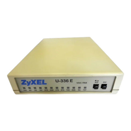
Front Panel Figure 2-1 shows the front panel of the U-336E. There are 10 LED indicators, a 20 x 2 LCD display, and four key switches. Figure 2-1 Front Panel Front Panel LEDs V.34 mode indicator, lights up when your modem is... - Page 20 Auto-Answer indicator, lights up when your modem is in the Auto Answer Mode; flashes when modem rings. In error control mode, it flashes when retransmitting. Carrier Detect indicator; lights up when a valid carrier is detected present on the line. Off-Hook indicator, lights up when your modem is in data mode or off-hook.
-
Page 21: Front Panel Switches
Toggles the modem on-line (off-hook, DATA mode) or off- line (on-hook, VOICE mode, the telephone set is connected to the line). Rear Panel Markings The U-336E rear panel is shown below: Figure 2-2 Rear Panel The following explains the connectors and switch on the rear panel. POWER Power switch, turns the modem ON or OFF. -
Page 22: Modem Connection
EIA-232D Serial port DB25S connector, for connection to the serial port of a DTE (computer/terminal). Pin assignments are listed in Chapter 11 Connector Pinouts for your reference. The signal- pin assignments for RJ-11 phone jacks are also listed in Chapter 11 Connector Pinouts. -
Page 23: Powering Up
Powering Up Once your modem’s power switch is turned ON, a series of diagnostic tests will be performed. For a more detailed description of these diagnostic tests, please refer to Chapter 9 Diagnostics & Troubleshooting. After performing the diagnostic tests, your modem is ready for use. Installation 11... - Page 24 12 Installation...
-
Page 25: Basic Modem Operation
Understanding AT Commands The U-336E communicates asynchronously with computers using AT commands. AT commands are used to configure and control your modem. Commands are usually sent to the modem by way of communication software, but can also be entered manually by the user with the computer keyboard. - Page 26 Terminal” program. This program provides a simple method to manually enter AT commands so you can do such things as “customize” the settings of your modem, or store commonly used phone numbers. Once your modem is connected to your computer’s serial port and telephone line, open the Windows 95 “Accessories”...
-
Page 27: Dialing And Answering Techniques
Your modem responds This confirms that the modem and your computer are communicating correctly. To test the telephone line connection issue the manual answer command. Type: ATA<Enter> Your modem will pick up the phone line, and try to communicate. Normally, this command is only used to answer an incoming call made from another modem, thus the high pitched tone you will hear from the speaker. -
Page 28: Auto-Answer And Hook Controls
Pausing During Dialing: ATDT 9,,555 1212 O O N S8. D HE PAUSE TIME FOR EACH COMMA IS DEFINED BY EGISTER EFAULT IS SECONDS PER COMMA Dialing Without Waiting for Dial Tone: ATX0D, 555 1212 Originating a call using an Answer Tone: ATDT 555 1212,,,,,,R Redialing the Last Number Called: ATDL Waiting for Five Seconds of Silence:... -
Page 29: Quick Tips When Issuing At Commands
Start the terminal program by double-clicking the Test Connection icon. When the terminal window appears, enter the dial command with ZyXEL’s BBS as the phone number. Type: ATDT17146930762 <enter> (Omit the ‘1714’ if you are in this area code) The modem will go off-hook, dial the number, and after a few seconds of negotiation tones, you should be connected to our BBS. - Page 30 Terminates the current connection attempt, if pressed while modem is handshaking. Escape code sequence. Entered while the modem is in Data Mode. Returns modem to Command Mode. The U-336E supports several groups of AT commands: AT Command Set/Type Example Basic AT (Hayes compatible) ATB0 Basic AT$ (on line help) Extended AT&...
-
Page 31: Modem Result Codes
An OK result code means the AT command you sent was executed. If you receive an ERROR code, it means the command was invalid. The U-336E also provides result codes that show: Whether or not a Dial Tone was detected when the modem originated a call. -
Page 32: Viewing S Register Values
modem uses. By default, your modem uses result codes equivalent to the ATX5 command. The result code options will be covered more thoroughly in later chapters. Viewing S Register Values Status registers (or "S-registers") contain values that determine the modem’s operating characteristics. Whenever you send an AT command to your modem, you are actually changing the value of an S-register. -
Page 33: Non-Volatile Memory
Non-Volatile Memory The U-336E has an amount of memory set aside for storing user information such as frequently used phone numbers and default command settings. The latter is particularly useful when using your modem to call a variety of different locations that require different settings. -
Page 34: Saving Settings And User Profiles
Saving Settings and User Profiles There are some cases where you may wish to save the settings you have made as the default settings that are recalled when your modem is powered up. The AT&WZ command selects the current settings as the power-on profile. There are four profiles that can be changed by the user, and one factory default profile. -
Page 35: Default Modem Settings For Pc's
SMARTDRV execution in your AUTOEXEC batch file. Default Modem Settings for PC’s The U-336E factory settings are configured for operation with PC type computers and communication software. In most cases, no additional settings will be required. The following are some of the... -
Page 36: Zyxel Serial/Parallel I/O Card
ZyXEL Serial/Parallel I/O Card For high-speed PC to modem communication, ZyXEL produces a special I/O adapter card. This card includes a serial port and a parallel port, each with special features, particularly when working with a ZyXEL modem, for example: The serial port is 16550-compatible for most communication software usage. -
Page 37: Mac Software Tips
Mac Software Tips All terminal programs which make use of the hardware handshaking feature can be used on the Apple Macintosh. Such programs are readily available as PD, shareware or commercial software. One of the most powerful shareware programs available is ZTerm. Fewer programs are available to make use of the ZyXEL's fax features. -
Page 38: Basic Modem Settings For Unix
Basic Modem Settings for UNIX Unix environments usually don’t like modem responses or echoing of commands. Therefore you should set ATE0Q1. Depending on your Unix setup, the cable and software used, you may have to disable carrier detection using AT&C0. Unix Software Tips In order to use your ZyXEL modem from a terminal or an X- Windows application, you need a program such as Minicom or... -
Page 39: Leased Line Operation
Your modem supports 2 -wire leased lines only. Connecting to a Leased Line The U-336E default line is a dial-up type. The leased line must be connected to the jack labeled Line. Set your modem for leased-line operation by typing commands from the terminal. The leased-line phone jack pin assignments are shown in Chapter 11 Connector Pinouts. -
Page 40: Manual Connect
answering modem can be commanded to either answer the call immediately, or after a specified number of rings. In a leased-line connection, the communication circuit between two modems is always present. Dialing and waiting for rings does not occur in this situation. If these two modems want to establish a data link, one must be designated as the originator and the other as the answerer. -
Page 41: Terminating A Leased Line Connection
Terminating a Leased Line Connection A leased line can be terminated two ways: Going on-line manually. Turning the power OFF and ON. If you have set the leased line as the power-on default, the modem will try the leased line again. - Page 42 30 Leased Line Operation...
-
Page 43: Special Functions
Special Functions This chapter describes special features of the U-336E, and offers instructions on how each is used. Security Functions Your modem provides a security function that prevents unauthorized users from making connections. Two types of security functions are provided. -
Page 44: User Passwords
With level 1 security, the local modem will maintain the connection if the password is OK, otherwise the line disconnected. With level 2 security, dial back the phone number corresponding to the dial-in password. The line simply disconnects if the password does not match. User Passwords Fifty user passwords may be defined. - Page 45 The following commands will enable different types and Verify: (Enter the new supervisor password again) ******** The command AT*Hn will modify the nth user password. You will be prompted to enter the supervisor password first and then be prompted to enter the nth user password. Levels of security: Command Function...
-
Page 46: Remote Configuration
Remote Configuration Remote configuration on the U-336E is provided as a profile by profile batch mode. When on-line, the remote modem’s current configuration or one of its profiles can be read into one of the local modem’s user profiles. This profile is modified locally and the line can be disconnected during this time. -
Page 47: Caller Number Delivery (Caller Id)
The remote profile read and write commands - *Rab and *Wab - only work in the on-line condition. The connection speed and mode do not matter. The remote modem must be set to accept remote configuration by executing the AT*F1 command. The AT*F0 command will set the modem up to deny remote configuration requests. - Page 48 There are two kinds of caller information message formats sent by the phone company. One is the single message format which includes date, time, and caller ID The other is the multiple message format which also includes the caller name as registered with the phone company. The command ATS40.2=n is used to enable (n=1) or disable (n=0) the Caller ID detection function.
- Page 49 CALLER NUMBER: 7135551414 or CALLER NAME: Brent Harper RING In the multiple message format, if the caller’s number and name are available, the ring message will display both: RING TIME: MM-DD hh:mm CALLER NUMBER: <Caller_ID> CALLER NAME: <Caller_Name> RING Here is an example: RING TIME: 04-28 12:30 CALLER NUMBER: 7135551414...
-
Page 50: Distinctive Ring
Setting S48.0=1 will cause the modem to report CND information in its ASCII coded hexadecimal raw data format. The DTE software is responsible for explaining the data. O O N TR-NWT- LEASE REFER TO THE ELLCORE ECHNICAL DVISORY DOCUMENT 000030 FOR THE EXACT DATA FORMAT HE ABOVE ALLER... - Page 51 commanded to answer or not answer any one of these four types of ring signals. Following is a list of these four types of ring signals. These are the ring types used in the USA. The difference among the ring types is the two-second ON part of the ring signal. It comprises a long, double short, or triple short ring.
-
Page 52: Extended Distinctive Ring (Edr)
Extended Distinctive Ring (EDR) Extended Distinctive Ring (EDR) is a special feature designed for single telephone line home use to receive fax or data calls without interfering with regular voice calls. When most users install a fax/modem at home, they won’t subscribe to an extra telephone line for occasional fax or data calls;... -
Page 53: Setting Up Edr
tone and report RING to the software immediately. The software application can then issue commands to answer the call and receive the fax. If the remote caller is using a fax phone which does not send out a CNG tone and is waiting for a fax answer tone in order to press the START button, the caller can press a designated DTMF tone, which will activate the modem to report and subsequently be ordered to answer the fax call. -
Page 54: Edr Application Example
EDR detection (either CNG or DTMF tones) will be disabled once detection occurs. However, a customer’s program might not answer because the setting of the software may require multiple rings to answer. S51 bits 0-1 control the number of rings that the modem will report once the CNG or DTMF tone is detected. - Page 55 3. Set S51.4=1 to enable fax CNG tone detection. It is reported as RING. 4. Set S51.2=1 to enable DTMF tone detection. It is reported as RING. If the remote fax machine does not generate the CNG tone, ask a fax caller through your answering machine message to press “*”...
- Page 56 44 Special Functions...
-
Page 57: Fax Operation
Fax Operation The U-336E can be used as a fax machine. In the sections below, we will describe how the modem works as a fax machine, the ITU- T T.30 fax protocol, the Class 1,2, and 2.0 fax commands and ZyXEL extended fax AT commands. -
Page 58: Modem As Fax Machine
entity, or individual. In order to program this information into the fax function of your modem, please refer to the documentation of the fax software you will be using. Modem as Fax Machine Modems can also be designed to include a fax transmitting and receiving function similar to a fax card. -
Page 59: Fax Command Sets
9600 bps and will automatically fall back to 7200, 4800, and 2400 bps if the line quality is poor. Fax Command sets The U-336E supports four command sets for fax operation: Class 1 command set TIA PN-2388 Class 2 command set TIA 592 Class 2.0 command set... -
Page 60: Class 1 Command Set
formally approved version is the Class 2.0 command set, also called the TIA-592 standard. Class 1 Command Set Command Value Description +FCLASS=n Service class selection Set to Data mode Set to Class 1 mode Set to Class 2 mode n=2.0 Set to Class 2.0 mode Set to ZFAX mode Set to Voice mode O O N... -
Page 61: Class 2 Command Set
Value Modulation Speed Requirements V.27ter 4800 required for FTM & FRM V.29 7200 required for FTM & FRM V.17 7200 required for FTM & FRM V.17 w/st 7200 required for FTM & FRM V.29 9600 required for FTM & FRM V.17 9600 required for FTM &... - Page 62 Command Value Description Determine if Copy Quality OK on the T.30 flow chart . <value>=0 to 255; a value of 0 implies that error checking is disabled. +FBOR=n Phase C data bit order: Select direct bit order. Select reversed bit order in receiving mode for phase C data.
- Page 63 Command Value Description br=1 Bit rate: 4800 bit/s; V.27ter. br=2 Bit rate: 7200 bit/s; V.29 or V.17. br=3 Bit rate: 9600 bit/s; V.29 or V.17. br=4 Bit rate: 12000 bit/s; V.17. br=5 Bit rate: 14400 bit/s; V.17. wd=0 Page width: 1728 pixels in 215mm. wd=1 Page width: 2048 pixels in 255mm.
- Page 64 Command Value Description +FDR Receive phase C data command; initiates document reception. +FDT=df,vr,wd, Transmit phase C data command: release the DCE to proceed with negotiation. +FET=n End of page or document command: More pages; same document. End of document; another document follows.
- Page 65 Command Value Description 9600 bps. 12000 bps. 14400 bps. +FPHCTO= 0-255 DTE Phase C response time-out: <value> Determine how long the DCE will wait for a command after reaching the end of data when transmitting in Phase C. <value>=0 to 255; 100 ms units. +FPTS=n Page transfer status Received page good.
- Page 66 Response Value Function and Description +FCFR Confirmation . +FCIG:"string" Report remote ID response CIG. +FCON Facsimile connection response. +FCSI:"string" Report remote ID response CSI. +FDCS:vr,br,wd,l Report session parameters response; n,df,ec,bf,st refer to +FDCC=..command. +FDIS:vr,br,wd,l Report session negotiation parameters n,df,ec,bf,st response;...
-
Page 67: Class 2.0 Command Set
Response Value Function and Description response. +FNSS:"HEX string" Report the non-standard setup frame response. +FPOLL Remote polling indication. +FPTS:n Receive page transfer status response; refer to +FPTS=n command. +FTSI:"string" Report remote ID response TSI. +FVOICE Transition to Voice response. Class 2 Flow Control Flow control is necessary to match the DTE-DCE data rate to the line signaling rate while transmitting or receiving Group 3 (T.4) data. - Page 68 Command Value Description ln,df,ec,bf,st +FDCC command in Class 2 for parameter settings. +FCLASS=n Service class selection. Refer to +FCLASS Class 1 command in previous section. +FCO DCE response fax connection made. +FCQ=<rq>,<t Copy quality check capability parameter q> rq=0 DCE Receive Copy Quality Checking disabled.
- Page 69 Command Value Description parameter Determine that T.4 EOL patterns are bit aligned (as received). Determine that the last received bits of T.4 EOL patterns are byte aligned by the DCE, with necessary zero fill bits inserted. +FIE=n Procedure interrupt parameter Procedure interrupt requests from the remote station are ignored, and not reported to the DTE.
- Page 70 Command Value Description +FMR? Request DCE revision identification. +FMS=n Minimum phase C speed parameter. refer to +FMINSP Class 2 command in previos section for parameter settings. +FNR=rpr,tpr, Negotiation message reporting control idr, nsr parameters: rpr=0 Receiver parameters are not reported. +FIS: and +FTC: response reports are suppressed.
- Page 71 Command Value Description +FPI="string" Local fax station ID string, for polling +FPR=n Serial port rate control parameter: Automatic DTE rate detection by the DCE. n>0 Serial rate is fixed at the value multiplied by 2400 bps. For example, when n=8, the DTE rate is equal to 19200 bps (8x2400).
- Page 72 Command Value Description Enable polling. Class 2.0 Command Responses Response Value Function and Description +FCI:"CSI ID Report remote ID response, Called string" Station ID +FCO Fax connection established response. +FCS:vr,br,wd,ln negotiated session parameters (DCS ,df,ec,bf,st frame information) response. Refer to +FIS= comnd.
- Page 73 Response Value Function and Description 90-9F Refer to TIA-592 for details. hsc= Receive phase D hang up codes. A0-BF Refer to TIA-592 for details. +FIS:vr,br,wd,ln, Remote fax station capabilities (DIS df,ec,bf,st frame information) response refer to +FIS=... command for a description of sub-parameters.
-
Page 74: Extended Fax At Command Set
Response Value Function and Description lbc: lost byte count +FTC:vr,br,wd,ln Remote fax station capabilities (DCT ,df,ec,bf,st frame information) response refer to +FIS=... command for the description of sub-parameters. +FTI: Remote ID response-Transmit "TSI ID string" Station ID (TSI). +FVO Report transition to voice. Extended Fax AT Command Set Extended Fax AT Commands are unique to ZyXEL modems. - Page 75 Command Function Set fax receiving mode. The messages are separated from the received fax data. The modem sends CONNECT FAX and ZyXEL first, then it waits for the DC2 character (hex18) to send the fax data. When the modem receives a DC2 from the DTE, it starts to send the fax connection parameters/SnnnnVnTnRnLnCnP<string><CR><LF >...
- Page 76 Status Report Result Codes When the U-336E is in fax mode, each ATD or ATA command will make the modem try to establish a fax connection. Your modem will send a status report result code back to the DTE (computer).
- Page 77 TONE NO CARRIER Handshake fails or no carrier is detected or time-out. BUSY Other party's phone line is busy. NO ANSWER Quiet answer is not detected before time-out. CONNECT FAX See below. When a fax connection is successfully established, the modem returns this message: CONNECT FAX/SnnnnVnTnRnLnCnP<string>...
-
Page 78: Flow Control
CONNECT and DISCONNECT status report result codes. The modem will always return the same status format as above. Flow Control In extended fax AT command mode, the U-336E always uses hardware (CTS/RTS) flow control. The flow control signaling used sending a fax is: CTS is used by your modem for DTE flow control. -
Page 79: Fax Reception From A Bbs
CD then send a status report result code to the DTE. Fax Reception from a BBS The U-336E can automatically detect data and fax calls and allow BBS software to receive faxes on the same phone line. To allow your BBS to receive incoming faxes, make the following set-up changes in your BBS: 1. - Page 80 2400 CONNECT 2400 38400 CONNECT 14400 Set external mail as: String Error Level 1 ZyXEL The following is a sample setting in the BINKLEY.CFG file for a Binkley system. Init AT&FX7S0=1#B1+FCLASS=6 ExtrnMail ZyXEL errorlevel 68 Fax Operation...
-
Page 81: At Command Set Summaries
AT Command Set Summaries Basic AT Command Set Command Options Function & Description Ref. Re-execute the last command once. A> Re-execute the last command once or repeat the last call up to 9 times. (See also S8) <any key> Terminate current connection attempt when enter in handshaking state. - Page 82 Command Options Function & Description Ref. 0-9, #, * Digits for dialing Pulse dialing S23.1 Ton dialing S23.1 Pause for a time specified in S8. Remaining digits will be dialed as in-band DTMF. Return to command state after dialing Hook flash Wait for a 5 second silence before proceeding Reverse handshake (go on-line in...
- Page 83 Command Options Function & Description Ref. Display product information and ROM checksum Display modem link status report Display physical layer status n=0-7 Speaker volume control. The higher S24.5-7 the value, the higher the volume Speaker control S21.1-2 Speaker always OFF M1 * Speaker ON until call is answered Speaker always ON...
-
Page 84: Description Of Ati2 Output
Command Options Function & Description Ref. Download firmware to the Flash EPROM by using Xmodem protocol Sets display type for Result Codes S23.6 Display result code in numeric form. (See also S35.7 and the result code table of 'ATXn') V1 * Display result code in verbose form. - Page 85 Max Block Size 0 Retrains Requested 0 Link Duration 0 Retrains Granted FRN Requested 0 FRN Granted FCS Errors 0 Round Trip Delay Xmitter Underrun 0 Receiver Overrun Last Speed/Protocol 33600 Disconnect Reason Local hang up Data Type Description Chars Data received from or sent to DTE (PC).
- Page 86 Output Output Value Description Parameter or protocol incompatibility.) Maximum blocks received without Outstanding acknowledgment by remote modem. Max Block Size Maximum octets contain in a block Retrains The number of times local modem requested Requested retrain. Link Duration Total link duration time (in minutes). Retrains The number of times remote modem requested Granted...
-
Page 87: Extended At& Command Set
Output Output Value Description Parameter Security check Inactivity ATH command D/V hang up Extended AT& Command Set Command Options Function & Description Ref. &Bn Data rate, terminal-to-modem. S28.6 (DTE/DCE) &B0 DTE rate follows connection rate. (See also S44.6) &B1 * DTE/DCE rate fixed at DTE setting (See also S18, S20, and S44.6) &Cn Carrier Detect (CD) options... - Page 88 Command Options Function & Description Ref. &G0 * No guard tone (within USA, Canada). &G2 1800 Hz guard tone. &Hn Data flow control, DTE/DCE. S27.3-5 &H0 Flow control disabled. &H3 * Hardware (CTS/RTS) flow control &H4 Software (XON/XOFF) flow control. &Jn Type of Phone line S28.0...
- Page 89 Command Options Function & Description Ref. &M3 Synchronous mode &Nn Modem link mode options (DCE/DCE). (See also S43.7, S48.1) &N0 * Multi-Auto, auto negotiate highest possible link rate: V.34, ZyX 19200, ZyX16800, V.32bis, V.32, V.22bis, V.22 and Bell 212A, G3 Fax V.17/V.29/V.27ter and cellular modes.
- Page 90 Command Options Function & Description Ref. &N13 V.23 600/75 (See also S52b7) &N14 V.22bis 2400/1200 &N15 V.22 1200 &N16 V.21 300 &N17 V.32bis 14400/12000/9600/7200/4800 &N18 V.32bis 12000/9600/7200/4800 &N19 V.32bis 7200/4800 &N24 BELL 212A 1200 &N25 BELL 103 300 &N32 G3 Fax V.17/V.29/V.27ter 14400/12000/9600/7200/4800/240 (See also S42.4).
- Page 91 Command Options Function & Description Ref. &N67 V.34 16800 &N68 V.34 14400 &N69 V.34 12000 &N70 V.34 9600 &N71 V.34 7200 &N72 V.34 4800 &N73 V.34 2400 &Pn Pulse dial make/break ratio S23.2 &P0 * make / break, 39% / 61% &P1 make / break, 33% / 67% &Rn...
- Page 92 Command Options Function & Description Ref. (RDL) test &T7 Initiate Remote Digital Loop-back with self test (RDL+ST) &T8 Initiate Analog Loop-back with self test. (ALB+ST) &Vn View profile settings. &V0 View current active settings. &Vn View the (n-1) user profile settings (n=1-4) &V5 View factory default settings.
-
Page 93: Extended At* Command Set
Command Options Function & Description Ref. &Z? Display all the phone numbers stored in non-volatile RAM. &Zn=s n=0-49 Write phone number/s to NVRAM at location n (n=0-49) use AT*Dn or ATS29=n to set the default dial pointer. Extended AT* Command Set Command Options Function &... - Page 94 Command Options Function & Description Ref. Enable type 1 security, with password check (ZyXEL to ZyXEL only) Enable type 1 security, with password check and call back (ZyXEL to ZyXEL only) Enable type 2 security, with password check Enable type 2 security, with password check and call back Enable type 2 security, with password check and call back,...
- Page 95 Command Options Function & Description Ref. No action to poor signal quality. Retrain action taken if signal quality is poor. (See also S41.2) *Q2 * Adaptive rate, automatic fall-back or forward. Disconnect if signal quality is poor. *Rab Read remote profile “b” to local S36.1 a=0-3 Local user profile number “a”...
-
Page 96: Status Registers & Result Codes
Status Registers & Result Codes S-Register Descriptions In most bit-mapped S-registers, the default bit value is 0. Non-0 default values are followed by an asterisk. In some cases, default values are shown in the reference column preceded by +. Some bits are reserved for factory use and should not be changed. -
Page 97: Extended S-Registers "Atsn=X
Command Function & Description +Ref. modem will dial as soon as it detects a dial tone. This register also sets the time-out interval for the “W” dial modifier to wait for the dial tone. (See also S41b4) Set duration, in number of seconds modem +060 waits for a carrier Set duration, in seconds, for pause (,) option... - Page 98 Command bit dec hex Function and description Ref. Answer mode Grant Remote Digital Loop- &T4 back test request Deny Remote Digital Loop- &T5 back test 3,2 0 Dial-up line (Default) &L0 2-wire leased line &L1 4-wire leased line &L2 5,4 0 Internal clock (Default) &X0 External clock...
- Page 99 Command bit dec hex Function and description Ref. Profile 2 as active settings after power on Profile 3 as active settings after power on 128 80 * Factory default as active settings after power on S16= dec hex Test status register +000 No test in progress &T0...
- Page 100 Command bit dec hex Function and description Ref. 0 * 0 Disable fixed baud function 1-46 1-2E Enable baud rate to be fixed when answering. Baud rate value settings (n) the same as S19= dec hex Modem connection mode, +000/ same &Nn 0-73 0-49 setting value as 'AT&Nn'...
- Page 101 Command bit dec hex Function and description Ref. 624000 bps 124800 bps 62400 bps 1A 41600 bps 31200 bps 24960 bps 1D 20800 bps 921600 bps Note: Only the speeds up to S20=15 are supported by auto speed detection. S21= bit dec hex Bit mapped register Maintain non-error control connection when modem error...
- Page 102 Command bit dec hex Function and description Ref. in synchronous mode. (Default) 6-7 0 Assume DTR always On &D0 108.1, DTR OFF-ON &D1 transition causes dial of the default number 128 80 108.2 Data Terminal Ready, &D2 DTR OFF causes the modem to hang up and return to command state 192 C0...
- Page 103 Command bit dec hex Function and description Ref. ATX7, error control result code enabled Display result code in numeric format (see S35.7) Display result code in verbose format Modem returns result code 128 80 Modem does not return result code (see also S40.1) S24= bit dec hex Bit mapped register 2-0 0-7 0-7 Ring Volume control,...
- Page 104 Command bit dec hex Function and description Ref. S38.5, S41.0) V.42+MNP4 &K3 V.42 + V.42bis (compatible &K4 with &K2) 3-5 0 Flow control disabled &H0 Hardware (RTS/CTS) flow &H3 control Software (XON/XOFF) flow &H4 control Reserved &H5 Signal quality No response to poor signal quality Retrain action taken if signal quality *Q1 is poor...
- Page 105 Command bit dec hex Function and description Ref. 4-5 0 No guard tone &G0 Reserved &G1 1800 Hz guard tone &G2 DTE/DCE rate follows link rate (See also S18, S44b6) DTE/DCE rate is fixed at the DTE setting, range from 300- 460.8 Kbps (default, also see S18, S44b6) 0 * Select V.22 for 1200 bps...
- Page 106 Command bit dec hex Function and description Ref. default number. Enable Selective Reject in V.42 (Default) Enable password protection to profile saving. When ‘AT&W0’ is issued, and profile 0 in the NVRAM has this bit set, the supervisory password will be requested. This bit in profile 0 also protects the supervisory password from a hardware reset.
- Page 107 Command bit dec hex Function and description Ref. Enable type 1 security with password check and call-back (ZyXEL to ZyXEL only) Enable type 2 security with password check 128 80 Enable type 2 security with password check and call-back 160 A0 Enable type 2 security with password check and call-back, remote site enters the call-back number...
- Page 108 Command bit dec hex Function and description Ref. 19200 Class 2 Fax mode DTE shifting: +FCON at current DTE, shift to 19,200 when entering into the next phase Disable srambler/descrambler in V.26bis mode. Enables compatibility with older V.26bis modems which have no such unit (default) S40= bit dec hex Bit mapped register...
- Page 109 Command bit dec hex Function and description Ref. for 0.5 sec DCD on-off transition Force S0>=2 128 80 Ignore calling tone, not to be used as fax detection S42= bit dec hex Bit mapped register +000 Enables throughput averaging CND message will be forced on even if AT02 is set Disable escape sequence code in answer mode...
- Page 110 Command bit dec hex Function and description Ref. off-hook and modem answering 128 80 Modem hang-up if the line condition does not permit modem to run highest speed set by ‘&Nn’ command S44= bit dec hex Bit mapped register +000 ATDSn initiates auto-dial of the stored numbers consecutively until connection...
- Page 111 Command bit dec hex Function and description Ref. S45= Delay during which the CND +087 0-FF silence detection is disabled, in 20 ms units. (See also S46) S46= dec hex CND silence detection interval +003 0-FF To process the CND, silence must be detected for the specified interval, in 20 ms units...
- Page 112 Command bit dec hex Function and description Ref. idle (waiting for command), it will not dial any number when DTR changes from ON to S49= bit dec hex Bit-mapped register +006 3-0 0-15 0-F Set cellular mode transmit power level -9 to -24 dBm. (See also S43b2) For cellular mode only.
- Page 113 Command bit dec hex Function and description Ref. DTMF tone Reserved 5-4 0 Disables fax-CNG tone detection (Default) Reports RING for fax CNG tone Reports RING 1 for fax CNG tone Reports RING 2 for fax CNG tone 7-6 0 Disables data CNG tone detection Reports RING for data CNG...
-
Page 114: Result Code Options
Command bit dec hex Function and description Ref. of 10ms, country specific S57= bit dec hex Bit-mapped register Enables the reporting of Class 1 capability in the response to +FCLASS=? Disabled busy detection when dialing is proceeding (Default) Enables busy detection in dialing period S62= bit dec hex Bit mapped register... - Page 115 The default value for ‘n’ is 5 when your modem is shipped. ATV0 ATV1 X0 X1 X2 X3 X4 X5 X6 X7 V V V V V V V V CONNECT V V V V V @ $ RING ** V V V V V V V V NO CARRIER V V V V V V V V...
- Page 116 ATV0 ATV1 X0 X1 X2 X3 X4 X5 X6 X7 CONNECT 624000 % % % % @ CONNECT 124800 % % % % @ CONNECT 62400 % % % % @ CONNECT 41600 % % % % @ CONNECT 31200 % % % % @ $ CONNECT 24960 % % % % @...
-
Page 117: Result Code Field Descriptions
Result Code Field Descriptions Field Name Possible Values Error_Code NONE, ARQ Error_Control LAPM, V42 (This field will not show if no error control is negotiated) Data_Compression V42b DCE_Speed All possible DCE speeds supported DTE_Speed All possible DTE speeds supported Connect Strings for Error Corrected Connections To enable the following numerical (ATV0) and verbose (ATV1) result codes when an error corrected connection is made, set S35 bit 7 to 1.(ATS35.7=1) - Page 118 106 Status Registers & Result Codes...
-
Page 119: Diagnostics & Troubleshooting
Diagnostics & Troubleshooting Diagnostics The U-336E is equipped with several diagnostic capabilities: Power-on Self Test. Analog Loop-back Test. Analog Loop-back with Self-Test. Local Digital Loop-back Test. Remote Digital Loop-back Test. Remote Digital Loop-back with Self-Test. The diagnostic tests listed above apply to several modes of operation: asynchronous or synchronous, error controlled or non- error controlled, data compression enabled or disabled data mode. -
Page 120: Resetting The Modem
DSP code checksum, DSP RAM memory, EEPROM, digital circuits, and the analog circuit calibrations. Results of the power-on self-test displayed on your terminal: 0 SYSTEM TESTING Self-test indicator. If no error occurs, ..this message will last until the end of the test. -
Page 121: Loopback Tests
Loopback Tests The Analog Loopback Test, Local Digital Loopback Test, Remote Digital Loopback Test can all be initiated with AT commands from the terminal. Use the AT&T0 command to terminate the test. Analog Loopback (AT&T1) This test can check almost every part of the modem and the RS-232 cable except the telephone line outgoing interface. -
Page 122: Indicator Lights
modem. This test is applicable when the remote modem does not provide V.54 Remote Digital Loopback capability. This test can be initiated by the local modem when the modems are on-line. Remote Digital Loopback Test (AT&T6) This test will request the remote modem to do a digital loopback. During testing, the local modem will send a remote digital loopback request to the remote modem according to V.54. -
Page 123: Line Condition Status Display
Dialing Indicator The V34 LED will flash on and off for 1/2 second each to indicate that the modem is dialing. This flash will continue after dialing until a carrier is detected. Therefore, the V34 LED will also flash in leased-line modem connections when one modem is trying to handshake but the other modem is not turned on. - Page 124 Received Signal Power Level (RX) This reading is expressed in 0.1 dBm resolution. The modem measured receiving signal power is generally within 1-2 dBm of the actual value with relative accuracy. The receiver sensitivity specification for your modem is -43 dBm. Strong signal power could cause signal saturation in the channel and degrade the data validity.
-
Page 125: Trouble Shooting
FRN Request (FR) The count of the local modem's requests to change the rate. Block Retransmitted (BR) The count of the blocks retransmitted (bad reception on the remote modem). FCS (Frame Check Sum) Errors (FE) The count of the FCS errors received (block errors) (bad reception on the local modem). - Page 126 Solutions 1. Make sure the DTR LED is ON. If it is OFF, make sure your communications software is using the same COM port as your modem. 2. You may have omitted the characters AT from the beginning of the command line. These characters must appear at the beginning of each command line.
-
Page 127: Command Echo Problems
Solution You may have typed a command that is not recognized by your modem or communications software. Command Echo Problems Problem You do not see any typed characters on your computer screen. Solutions 1. Make sure the DTR LED is ON. If it is OFF, make sure your communications software is using the same COM port as your modem. -
Page 128: Dialing Problems
have the modem answer on the first incoming ring To auto- answer after a specific number of rings, replace 1 with a value up to 255. Do not assign a value of 0, which turns off auto- answer, unless your software can respond to the modem’s RING result codes. -
Page 129: Data Transfer Problems
Data Transfer Problems Problem You can make a data connection with a remote modem, but encounter frequent errors during data transfers. Solutions 1. Your modem and communications software may be configured for different flow control methods. Be sure your modem and software are both using hardware (RTS/CTS) flow control or software (XON/XOFF) flow control. -
Page 130: Upgrading Your Modem
Upgrading Your Modem Upgrading by Flash EPROM 1. Obtain the new firmware by downloading from the ZyXEL BBS, WWW or FTP site. See Contacting ZyXEL on page vi for the FTP address. 2. Turn on your computer. 3. Turn on your modem. 4. -
Page 131: Kernel Recovery Mode
Kernel Recovery Mode Your modem is equipped with ZyXEL’s exclusive Kernel Recovery Mode. This unique feature enables quick recovery from failed flash uploads. With other modems, a failed flash upload usually results in the user having to return the modem to the factory for repair. -
Page 132: Connector Pinouts
Connector Pinouts Phone Jack Pinouts The ZyXEL U-336E modem features two RJ-11 phone jacks, one for 2-wire dial-up and 2-wire leased line connection (LINE) and one for an optional connection to a telephone set (PHONE). The signals on these pins are:... - Page 133 Signal ITU-TSS Pin/Signal Direction Signal Signal Description DTE-DCE Name Name Data Set Ready (DSR). Signal Ground (GND). Data Carrier Detected (DCD). Transmit Clock Signal (source: DCE). Synchronous Receive Clock. Local Analog Loopback Test. 108/2 Data Terminal 108/1 Ready (DTR). Connect DCE to line Remote Digital Loop Test.
-
Page 134: Macintosh Serial Port Pinouts
Macintosh Serial Port Pinouts The following table shows the wiring of a modem Macintosh hardware handshaking cable: Modem Description Din 8 DB 25 4 & 20 DTR to RTS and DTR, Hardware Handshaking Out CTS to CTS, Hardware Handshaking In TX- to TXD, Data sent GND, Ground RX- to RXD, Data received... - Page 135 Connector Pinouts 123...
- Page 136 Index AT commands, 5, 13, 14, 15, 17, Kernel Recovery, 122 18, 19, 21, 32, 45, 62, 63, 66, LCD display, 7, 10 111, 115, 116, 122 Leased Line Handshaking, 28 Combining, 17 Auto, 28 Quick Tips, 17 Manual Connect, 28 ATI2 Output, 72 Leased Line Operation Auto-Answer, 8, 16...
- Page 137 Result Code Options Answer Problems, 118 "ATXn", 104 AT Command Set Problems, Result codes, 18, 19, 20, 45, 62, 66, 95, 106, 116, 117, 118 Command Echo Problems, 117 Saving Settings, 22 Connection Problems, 119 Security, 4, 31, 32, 33, 82, 96 Data Transfer Problems, 119 Functions, 31 Dialing Problems, 118...