
Related Manuals for ZyXEL Communications U-1496 series


Summary of Contents for ZyXEL Communications U-1496 series
- Page 1 ZyXEL U-1496 Series Modems User’s Manual Copyright 1994-1997 by ZyXEL Communications Corp.
-
Page 2: Chapter One - Introduction
HOW TO USE THIS MANUAL This manual describes the use of all models in the U-1496 series, the U-1496, U-1496E, U-1496B, U-1496P, and U-1496R. Usually, this manual describes the operation of the U-1496, the model with the largest set of functions. - Page 3 U-1496 series modems' features, introduces some basics of modem operation for novice users, and explains the installation of the different models of the U-1496 series including the U-1496B PC-card. Please note that the COM port and interrupt number must be properly chosen, before the U-1496B can be installed.
- Page 4 Note: V.33, V.29, V.27bis, V.27ter and V.26bis are only available in models U-1496 and U-1496R for 4-wire leased line operation. The other operation modes are common to all models. THE U-1496 SERIES STANDARD FEATURES Synchronous/Asynchronous operations for external stand alone models and rack mount model.
- Page 5 Programmable speaker volume control. Non-volatile memory storage. Remote configuration. Security call back. Caller ID detection. Distinctive ring detection. Extensive Status reports. Diagnostics available for: Modem full self test Analog loopback (w/ self test) Remote digital loopback (w/ self test) Digital loopback XON/XOFF or CTS/RTS flow control.
- Page 6 Before you proceed further, please check to see if you have all the necessary materials from the shipping package and make sure nothing is missing. The complete package should include: one (1) U-1496 series universal modem one (1) power adapter pack (stand alone model only) one (1) RJ11 telephone cable...
-
Page 7: Connecting To Your Phone
Communication software controls the modem connected to the computer and directs data to and from the modem. For most cases in the PC environment, the modem is used in an asynchronous mode and the software controls the modem by the AT commands. ZyXEL modems support the extended AT command set and are compatible with most communication software packages. -
Page 8: Synchronous And Asynchronous Communication
telephone network and reach the other modem. The remote modem translates the analog signal received back into data (demodulation) and sends the information to the receiving end computer. Modems are telephones for computers, what they use to talk to each other. ((*MODE-02*;... -
Page 9: Modem Standards And Speeds
Bell 212A for 1200 bps modems and Bell 103 for 300 bps modems. Everyone is following the CCITT standard now for newer and higher speed modems. ZyXEL U-1496 series modems support all the above mentioned modem standards and are compatible with existing modems. TYPE OF TELEPHONE LINE The commonly used phone service is a 2-wire dial-up line. -
Page 10: Intelligent Modem
A leased-line phone service is also available from phone companies in a 4-wire form. Here the transmitting and receiving signal each uses a separate 2-wire pair and thus no echo problem will result. Normally, no DC current feeding, ringing, or dialing function is provided on a leased line. There is also the case of a 2-wire leased line which is a permanent 2-wire connection. -
Page 11: Error Correction
interfaces and finds most of its use in Europe and IBM mainframe or mini environments which use synchronous communication. ERROR CORRECTION In synchronous data communication, data is checked and corrected in the host by the so called "link layer protocol" to ensure data integrity. -
Page 12: Xmodem, Ymodem, And Zmodem
V.42bis is used with V.42 for error correction. XMODEM, YMODEM, AND ZMODEM These are file transfer protocols used by the host (e.g., the communications program in the PC). It does error checking and ensures data integrity of the file transferred. Some variations of these protocols also appear, like Xmodem-1k, Ymodem-G, etc.. -
Page 13: Autodetection Of Fax Or Data Call
internal PC plug-in card. External stand alone units can be connected to any computer with a standard RS-232 serial port. This computer need not be a PC. EIA CLASS 2 FAX COMMAND The EIA class 2 fax command is a set of AT fax commands defined by EIA/TIA (Telecommunications Industry Association) for controlling faxmodems from a computer through the serial RS-232 interface. -
Page 14: Cellular Modem
Most modems will automatically redial a telephone number several times, if a connection could not be established on the first try. The modems of the U-1496 series also offer the ability to do cyclic redials of a set of up to ten different numbers. -
Page 15: Chapter Three - Modem Installation
Chapter Three - MODEM INSTALLATION This chapter describes the panel function and installation guide for model U-1496, U-1496E, and U-1496P. The U-1496R comes with its own installation guide. The installation guide for U-1496B is in Chapter 18. A shielded RS-232 cable is required to ensure compliance with FCC Part 15, and it is the responsibility of the user to provide and use a shielded RS-232 cable. -
Page 16: Leased Line
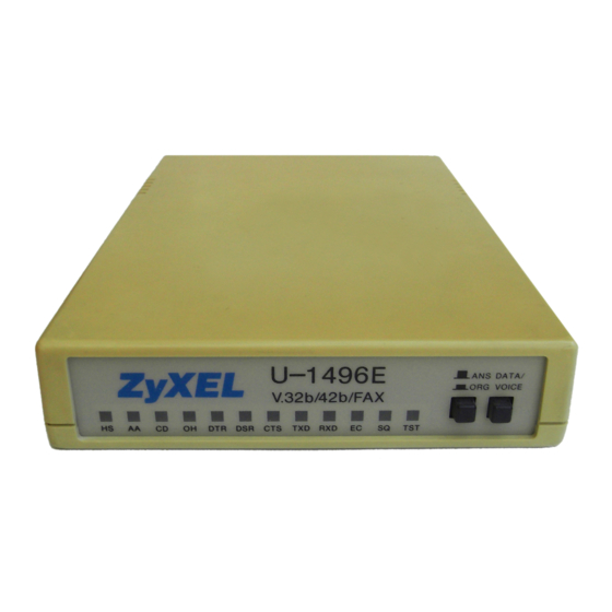
LEASED LINE Leased-line JM8 terminal jack, for connection to a 2/4-wire leased line. DIAL-UP LINE Dial-up line RJ11 terminal jack, for connection to a 2-wire dial-up line. PHONE Telephone line RJ11 terminal jack, for connection to a telephone set. EIA-232D Serial port DB25S connector, for connection to the serial port of a DTE (computer/terminal). - Page 17 LED Indicators HS High Speed indicator, lights up when modem is in V.32 or V.32bis mode. Dialing indicator, flashes one second on and one second off when dialing. Retrain indicator, flashes half second on and half second off when modem is in retrain. AA Auto-Answer indicator, lights up when modem is in the Auto Answer mode;...
- Page 18 U-1496E does not have the leased line jack. ((MODE-37)) Refer to U-1496 rear panel description and modem connection for U-1496E's rear panel explanation. U-1496P FRONT PANEL Fig. 3-7 shows the U-1496P front panel. The following explains the connectors and indicator on the front panel. ((Figure 3-7: U-1496P FRONT PANEL - redraw)) POWER Power jack connector for power connection.
- Page 19 convenient method. The cellular adaptor available from certain vendors will adapt a specific cellular phone unit to a normal 2-wire phone interface for the modem connection. It provides dial tone and ring signal to the modem. Because of the absence of a cellular interface standard, a special cellular adaptor is needed for each specific cellular phone.
-
Page 20: Chapter Four - Quick Start
Chapter Four - QUICK START This chapter tells you how to dial and answer on a modem. If you use this modem with a PC, you probably don't need to worry about modem settings. The factory default may be just right for you. Connect the modem according to instructions in Chapter 3, install the communication software on the PC, make the modem dial as instructed in this chapter, and you're all set. -
Page 21: Led Status Screen
options selection. Up arrow key also called the MENU key, is used for vertical menu selection and is used to access the previous menu. The up arrow key also serves as a quit command when you want to stop the current action. -
Page 22: Dial Memory
Return to COMMAND STATE 5 second silent wait Hook flash Pulse dialing Reverse dialing Tone dialing Wait for dial tone Digit separator <bs> backspace DIAL MEMORY The first menu of the Dialing Directory is DIAL MEMORY. Pressing the ENTER key will show the following screen: ((MODE-10 (mod.))) Equivalent AT commands: AT&Z? -
Page 23: Dial Number
press ENTER again to save the entry in the EEPROM. The stored numbers will remain in memory until you revise or delete them. Pressing the up arrow key in the process will abort and exit the current number entry and nothing will be changed or saved. DIAL NUMBER The same procedure is used when entering numbers, as in the STORE NUMBER operation. -
Page 24: Repeat Last Dial
answer mode on-line. Whenever your modem establishes a connection with another modem, one of the modems must be in answer mode and the other modem must be in originate mode or a connection is not possible. Equivalent AT commands: +++ Escape sequence code; causes a modem to return to command mode. - Page 25 ((MODE-14)) then the modem will go back to the IDLE STATUS screen. If the line is busy, after 3-5 seconds, the LCD displays: ((MODE-15)) then goes back to IDLE STATUS screen. If the phone company is ringing the remote modem, a RINGING message is sent to the terminal.
-
Page 26: Panel Lock
Retrain Granted Retrain requested 0 Round trip Echo Delay 128 T (1/2400 sec) Carrier Loss counts 0 The ON-LINE STATUS screen 4 shows: FRN (Fast Rate reNegotiation) Granted 0 FRN Requested 0 Blocks Retransmitted FCS (Frame CheckSum) Errors 0 Pressing the left or right arrow key in any one of the ON-LINE STATUS screens will cause the LCD to scroll through the three screens. -
Page 27: Parameter Menu
parameters using the U-1496 CONFIGURATION menu tree. U-1496E, U-1496P, and U-1496B users can also consult this menu tree for available parameter options, but use the equivalent AT command to set the parameter. Here we define the various levels of the CONFIGURATION menu tree CONFIGURATION menu submenus parameter menus... -
Page 28: Menu Tree Elements
To save the current parameter settings to non-volatile EEPROM, access the SAVE TO submenu in the CONFIGURATION menu and select from the various profiles you wish to save the changes to, and the parameter settings will be permanent in that profile. You can always recall in these settings by resetting from that profile. -
Page 29: Character Length
connection. CHARACTER LENGTH 10 AT*C0 10-bit characters. 11 AT*C1 11-bit characters. AT*C2 9-bit characters. AT*C3 8-bit characters. The character length includes start bit, data bits, parity, and stop bit(s). COMMAND SET AT AT*I0 Modem accepts asynchronous AT commands. V.25bis AT*I1 Modem accepts asynchronous or bit-oriented synchronous V.25bis commands. - Page 30 TRACKS CARRIER AT&C1 DCD ON when carrier is detected. (see also S38b3). If S42.7=1, DCD only pulses off for 0.5 sec when carrier loss happens. ALWAYS ON AT&C0 Modem forces DCD always ON. RTS OPTIONS IGNORED AT&R1 Modem assumes RTS always ON, ignores the changes.
- Page 31 1200 MODEM OPTIONS LINK OPTIONS MULTIAUTO AT&N0 Auto handshaking with ZyX19200 19200 Zyx16800 16800 V.32bis 14400/12000/7200 V.32 9600T/9600/4800 V.22bis 2400/1200 V.22 1200 BELL 212A 1200 G3 Fax 14400/12000/9600/ 7200/4800/2400 (V.17, V.29, V.27ter) Cellular Modes 14400 to 2400 V.33 14400 AT&N1 V.33 14400/12000 V.33 12000 AT&N2...
- Page 32 CELL 9600 AT&N44 CELL 9600 CELL 7200 AT&N45 CELL 7200 CELL 4800T AT&N46 CELL 4800T CELL 4800C AT&N47 CELL 4800C CELL 3600C AT&N48 CELL 3600C CELL 2400C AT&N49 CELL 2400C Note: @: All ZyX modes except ZyX 16800 are available only on Plus models.
-
Page 33: Make/Break Ratio
DENY AT&T5 Ignores remote digital loopback test request from remote modem. LLINE ???Spelling okay??? TX POWER 0 to -15 dBm AT*P0-15 Select transmit power from 0 dBm to -15 dBm. Default is -9 dBm. Effective in leased line operation only. Select in the range of -12 to -27 dBm when S35 bit 3 is set. - Page 34 will handshake in originate mode. ANSWER AT*M1 When operating over a leased line, modem will handshake in answer mode. Note: If you need two modems to automatically connect on a leased line when power is turned ON, one modem must be set to originate mode, and the other set to answer mode.
-
Page 35: Audio Options
A value of 0 disables the ring function. Chapter Six - PROFILES The U-1496 series modems let you save up to 4 sets of configurations, which are called Profiles. You can save the entire modem configuration in the non-volatile EEPROM memory for use as the default settings, or you can use it as the power-on default. - Page 36 can modify these profiles and save them for your specific applications. You can view each set of profile settings by typing AT&Vn (n=0-5) from the terminal. Following are the commands and their responses. The value shown for each register is a decimal number. AT&V0 Current Settings....
- Page 37 Profile 0 satisfies most asynchronous applications. ZyXEL preset this profile to be the same as the factory default. A summary of this profile is: DTE speed 38400 bps Link Option MULTI-AUTO Data Format ASYNC Command Set AT 108.2 Data Terminal Ready Ignored Tracks Carrier Always On...
- Page 38 Ignored Tracks Carrier Always On Error Control V.42bis + MNP5 Flow Control CTS/ RTS Quality Action Adaptive Rate Line Type 2W Leased Line Terminal Keyboard Aborting Disabled Auto Handshake Originate AT&V3 Profile 2 Settings....&B1 &C1 &D2 &G0 &H0 &J0 &K0 &L0 &M3...
- Page 39 &B1 &C1 &D0 &G0 &H0 &J0 &K0 &L2 &M3 &N0 &P0 &R0 &S0 &X0 &Y1 S00=000 S01=000 S02=043 S03=013 S04=010 S05=008 S06=003 S07=050 S08=002 S09=006 S10=007 S11=070 S12=000 S13=000 S14=200 S15=130 S16=000 S17=018 S18=000 S19=000 S20=002 S21=018 S22=000 S23=105 S24=138 S25=000 S26=000 S27=128...
-
Page 40: Profile Protection
S50=000 S51=000 S52=000 S53=000 S54=000 S55=000 S56=000 S57=000 S58=000 S59=000 Factory default setting is stored in ROM, ZyXEL presets User Profile 0 the same as the factory default. RESET FROM PROFILE You can reset the modem and load a user profile as the active settings, or you can designate a user profile as the power-on default profile. -
Page 41: Reset Profiles
(see Chapter 6). The U-1496 series modems have 60 S-Registers from S0 to S59. S0 to S11 are standard AT S- Registers; and S13 to S49 are mostly bit-map configured. Changes in the bit-map configuration can also have the same effect as issuing commands. -
Page 42: S-Register Descriptions
to set only bit 'b' of S-Register 'r' to value 'n' without affecting other bits in this S-Register. When using ATSr = n, you need to do a conversion to or from the binary number to find out the bits. For example, if you want to set S38 bit 3 to 1 for a specific application: Do an ATS38 = ? to find the original value. - Page 43 Default=8; Holds the ASCII decimal value of Backspace character. A value of 128- 255 disables the Backspace key's delete function. Default=3; Sets the number of seconds the modem will wait before dialing if X0 or X1 is selected. If X2, X3, X4, X5, X6, or X7 is selected, modem will dial as soon as it detects a dial tone.
- Page 44 2 stop bits. (1,0) Even parity. Odd parity. No parity. Test status register, default = 0 No test in progress. (Default) Analog loopback test in progress. Reserved. Local digital loopback test in progress. Remote digital loopback test in progress. Remote digital loopback with self-test in progress. Analog loopback with self-test in progress.
- Page 45 =32; V.17FAX 14400/12000/9600/7200, V.29FAX 9600/7200, V.27terFAX 4800/2400. =34; ZyX 19200 19200 =35; ZyX 16800 16800 =36; ZyX 14400 14400 =37; ZyX 12000 12000 =38; ZyX 9600 9600 =39; ZyX 7200 7200 =42; CELL 14400 14400 =43; CELL 12000 12000 =44; CELL 9600 9600 =45;...
- Page 46 (2,1) Speaker always OFF. Speaker ON until carrier is detected. Speaker always ON. Speaker ON after last digit is dialed out until carrier detected. Maintain non-error control connection when error control handshake fails. Drop connection when error control handshake fails. Reserved.
- Page 47 MNP4 + MNP5. (See also S41b0, S38b5) V.42 +MNP4. V.42 + V.42bis (compatible with &K2, see also S38b5). Bit-mapped register, default = 068, Select V.22 for 1200 bps communication. Select Bell 212A for 1200 bps communication. &Bn DTE/DCE rate follows link rate. (See also S18, S44b6) DTE/DCE rate fixed at DTE setting, range from 300 to 76.8 Kbps.
- Page 48 control connection is made, used with ATV0 (S23b6), see result code table. Enable password protection to profile saving. When AT&W0 is issued and profile 0 in the EEPROM has this bit set, supervisory password will be requested. Enable Selective Reject in V.42 Effective only on the U-1496E and U-1496R.
- Page 49 Bit-mapped register, default = 000 Does not include resync information in recorded voice data. Includes resync information in recorded ADPCM file. Note: When the resync function is enabled, the modem sends a resync symbol - <DLE><DC2>(hex 10 and 12) every 50 ms. ADPCM data can be edited without losing sync if enabled.
- Page 50 Disable "RINGING" result code. (See ATXn). button. V.17 fax in calling mode, no effect on answering mode (See &N0 and &N32). Disable escape sequence code in answer mode. CND message will be forced on even if ATQ2 is set. (See S40b1).
-
Page 51: Chapter Eight - At Command Set Summary
S51 - S59 Reserved Chapter Eight - AT COMMAND SET SUMMARY An AT command is a command issued by the computer/terminal to the modem through the RS232 serial port in asynchronous data format when the modem is in command state. An `AT' command prefix (ATtention) precedes each command line, except in the case of `A/', `A>>', and `+++'. - Page 52 Display product code <197> "1496" for U-1496 series modems. Same as ATI. Display ROM checksum and product information. Display link diagnostic status report. L0-7 Speaker volume control. The higher the value, the higher the volume (Default is L4). Speaker always OFF.
- Page 53 CONNECT 9600 CONNECT 19200 CONNECT 7200 CONNECT 12000 CONNECT 14400 CONNECT 16800 CONNECT 38400 CONNECT 57600 CONNECT 76800 Notes: +: If error control result codes enabled (X5, X6, or X7), the result message will be formatted as: CONNECT DTE speed/Link speed/*Error control level - X5 CONNECT Link speed/ARQ - X6 CONNECT Link speed/ARQ/*Error control level - X7 where ARQ means Automatic Retransmission reQuest type of error control is...
-
Page 54: Extended At& Command Set
CONNECT 7200 CONNECT 9600 CONNECT 12000 CONNECT 14400 CONNECT 16800 CONNECT 19200 Reset modem and load user profile 0. Reset modem and load user profile 1. Reset modem and load user profile 2. Reset modem and load user profile 3. Reset modem and load factory settings, also set factory default as power-on profile. - Page 55 &J0 Single phone line RJ11 phone jack (Default). &J1 Multiple phone/modem lines RJ12/RJ13 phone jack. &K0 No error control. &K1 MNP4 (includes MNP3). &K2 MNP4 + MNP5. (See also S38b5, S41b0.) &K3 V.42 +MNP4. &K4 V.42 + V.42bis, compatible with &K2 (Default). (See also S38b5.) &L0 Normal 2-wire dial-up line (Default).
- Page 56 &N43 CELL 12000 &N44CELL 9600 &N45 CELL 7200 &N46 CELL 4800T &N47 CELL 4800C &N48 CELL 3866C &N49 CELL 2400C Note: All speeds over 9600 bps are trellis coded except V.29; V.32bis 7200 is also trellis coded. Not all modes available in all models. Check the compatibility table. All ZyXEL modes except ZyXEL 16800 are available only with Plus models.
-
Page 57: Extended At* Command Set
break is sent immediately.) &Y1 Non-destructive break, expedited (Default). &Y2 Non-destructive break, un-expedited. &Zn=s Store the dial string (s) to EEPROM at location n (n=0-9). &Z? Display all the phone numbers stored in EEPROM. EXTENDED AT* COMMAND SET Disable dial-backup (Default). Enable dial-backup and set dial-backup pointer at location n-1. - Page 58 Note: These commands *Hn and *HS need supervisory password checking. Any character can be entered in the password (0-255). Maximum password length is eight. AT command set (Default). V.25bis command set. Dumb mode. Note: Enter RST command in V.25bis mode will revert modem to asynchronous AT command mode.
-
Page 59: Chapter Nine - Error Control And Data Compression
Chapter Nine - ERROR CONTROL AND DATA COMPRESSION ERROR CONTROL Error Control keeps the modem data link error free by detecting and retransmitting the data in error. ZyXEL modems support both MNP and V.42 error control protocols. The MNP protocol was an industry de facto standard developed and licensed by Microcom, Inc. -
Page 60: Data Compression
The token is sent for the longest matched string. Compressibility is high if there are some regularities of character pattern in the data. For the U-1496 series of modems, the error control and data compression option can be enabled from the front panel or terminal. - Page 61 Though data compression protocols of V.42bis and MNP5 are bidirectional, most modems slow down when doing bidirectional file transfers because of limited processing power. ZyXEL U-1496 series modems use the powerful 68000 processor that do not slow down during bidirectional file transfers.
-
Page 62: Flow Control
This feature refers to stopping and restarting the flow of data into and out of the modem's transmit and receive data buffers. Flow control is necessary so that a device (computer or modem) does not receive more data than it can handle. The U-1496 series modems provide two kinds of flow control methods. -
Page 63: Clock Options
terminal. Be sure that the remote modem and system are also set to synchronous. Synchronous operation applies to all the non-FSK modes that the modem is supplied with. The U-1496, U-1496E, U-1496P, and U-1496R stand alone, portable, and rack mountable models support synchronous mode operation, but the U-1496B has a built-in PC asynchronous serial port and can only be used in asynchronous mode. -
Page 64: Dial From Synchronous Mode
SYNC DATA AT&M1 Modem accepts asynchronous command in command state, but exchanges data synchronously in data state. SYNC AT&M3 Modem accepts synchronous command (V.25bis) and exchanges data synchronously with a remote modem. You can always use panel operation to control and configure the modem and use manual dial and answer to operate the modem. -
Page 65: Manual Answer From Synchronous Mode
MANUAL ANSWER FROM SYNCHRONOUS MODE Type `ATA' from the terminal (if set &M1) or press `A' on the IDLE SCREEN menu from the front panel. On the U-1496E, press the VOICE/DATA switch with the ANS/ORG switch set to ANS. CHANGE FROM SYNCHRONOUS MODE TO ASYNCHRONOUS MODE Set the modem to asynchronous mode from the panel, or just reset from an asynchronous profile. - Page 66 2W LEASED AT&L1 Modem connected to 2-wire leased line, the line plug should be plugged into the jack assigned 'LEASED LINE' on the rear panel. 4W LEASED AT&L2 Modem connected to 4-wire leased line. Plug the line into the 'LEASED LINE' jack.
-
Page 67: Leased Line Dial-Backup
The U-1496, U-1496R, U-1496P, and U-1496E support both asynchronous and synchronous leased line operation. Choose a suitable modem link mode. If the signal to noise ratio of your leased line is guaranteed above 25 dB, V.32bis 14400 is a better choice. V.32bis 14400 is also compatible with V.32bis 12000/7200 and V.32 9600T/9600/4800. -
Page 68: Chapter Twelve - Special Functions
Two types of security functions are provided. Type 1 security is used when the remote modem is also a U-1496 series modem; type 2 security function is used when the remote modem is any other brand modem. In the type 1 connection,... -
Page 69: Remote Configuration
REMOTE CONFIGURATION The U-1496 series modems provide the remote configuration capability that a local modem can configure the remote modem and reconnect at the new configuration. Remote configuration is provided at a profile to profile batch mode. -
Page 70: Caller Number Delivery (Cnd)
With CND service, the phone company central office will send the coded caller information to the called station. This information is sent once between the first and second ring. U-1496 series modems are equipped with the capability to decode this caller information and present it to the connected computer/terminal during the second ring period as part of the call progress ring message. - Page 71 RING 04-28 12:30 7135551414 RING For a multiple message format, if the caller's number and name are available, the ring message will be RING TIME: MM-DD hh:mm CALLER NUMBER: <Caller_ID> CALLER NAME: <Caller_Name> RING Following is an example: RING TIME: 04-28 12:30 CALLER NUMBER: 7135551414 CALLER NAME: Michael Smith RING...
- Page 72 `ON' part of the ring. The U-1496 series modems can distinguish up to four types of ring signals and can be commanded to answer or not answer to any one of these four types of ring signals. Following is a list of these four types of ring signals. These are the ring types used in the USA.
-
Page 73: Chapter Thirteen - Cellular Mode Operation
V.25bis mode. Chapter Thirteen - CELLULAR MODE OPERATION ZyXEL U-1496 series modems are equipped with a special communication mode - cellular mode - which enables the modem to perform reliable high speed data transmissions over a cellular phone link. Although all ZyXEL U-1496 series modems provide the cellular mode, the U-1496P portable modem is specially designed for portable use. - Page 74 Besides physical layer enhancements, ZyXEL also does V.42 link layer enhancements. ZyXEL CELLULAR MODES In addition to normal modem, fax, and voice operation modes, the following cellular modes are offered in the U-1496 series modems: Mode Speed Multi-Auto ZyX modes/V.32bis/V.32/V.22bis/G3 FAX/Cellular Modes...
-
Page 75: Cellular Mode Usage
CELL 4800T uses a trellis coded modulation at 4800 bps speed. It has a better performance than the uncoded V.32 4800 bps mode. CELL 4800C uses forward error correction to get a low error rate at 4800 bps net link speed. CELL 3600C and CELL 2400C also use forward error correction to get a net speed of 3600 bps and 2400 bps. -
Page 76: Chapter Fourteen - Fax Operation
The modem shields the computer fax software from the T.30 protocol handling. Along with T.30, the U-1496 series modem provides the highest fax speed up to 14400 bps using the new fax transmission standard V.17. When connecting to an existing non-V.17 fax device, the modem provides a highest speed of 9600 bps and will automatically fall back to 7200, 4800, and 2400 bps if the line quality is not good enough. - Page 77 +<command>=<value> Execute a command or set a parameter +<command>? Read possible settings +<command>=? Read current setting Supported Commands (per EIA PN2388 8/20/90) +FAA=n Auto answer mode parameter DCE to answer as set by +FCLASS DCE can answer and auto. determine calling type +FCLASS=n Service class selection Set to modem mode...
- Page 78 +FET=n End the page or document command More pages; same document End of document; another document follows No more pages or documents Procedure interrupt: another page follows Procedure interrupt: end of document, another document follows Procedure interrupt: end of document +FLID="string"...
- Page 79 (RTS/CTS) and software flow control (XON/XOFF) are enabled. Extended FAX AT Commands These commands are unique to the U-1496 series modems. The computer controls the modem through a set of extended fax AT commands and the modem responds with a set of status report result codes.
-
Page 80: Status Report Result Codes
Set recording width: 1728 picture elements along a scan line length of 215mm. Set recording width: 2048 picture elements along a scan line length of 255mm. Set recording width: 2432 picture elements along a scan line length of 303mm. Set maximum recording length: A4 (297mm ). Set maximum recording length: B4 ( 364mm ). -
Page 81: Flow Control
Coding scheme; n=0 or 1. Recording width; n=0, 1, or 2. Recording length; n=0, 1, or 2. Scan line time; n=0 to 7. P<string> Remote fax number. After each fax disconnection, the following result code is sent back to the DTE (computer): DISCONNECTnP <string>... -
Page 82: Chapter Fifteen - Advanced Voice Capability
Plug the phone cable from the wall jack into the modem's Line Jack. Plug the phone cable from the fax machine into the modem's Phone Jack. Power on the DTE terminal and set S38 bit 4 of the modem to 1 by sending the command "ATS38.4=1"... -
Page 83: Voice Data Compression
28800 bps where the sampling rate used is 9600 samples per second. The ADPCM voice modes are supported on all U-1496 series modems. However, the advanced CELP scheme is supported only on the plus models, including the U-1496 LCD model. -
Page 84: Voice At Commands
New capabilities or enhancements will be released in future versions of its firmware. VOICE AT COMMANDS The U-1496 series modems support a set of voice AT commands. These commands are basically consistent with the TIA TR29.2 committee PN-2986 document. ZyXEL is continuously enhancing its modem's voice capability and voice command implementation. - Page 85 FLOW CONTROL Software XON/XOFF flow control is used. SUPPORTED COMMANDS FOR VOICE MODE OPERATION AT+FCLASS=<mode> This command selects a DCE mode as follows: <mode> = 0 (Default), Data mode. <mode> = 2, Fax mode. <mode> = 8, Voice mode. Result codes: The DCE issues this result code if DCE accepts this command.
- Page 86 ATH (with AT+FCLASS=8) This command causes the DCE to hang up the phone with the following considerations for a hang up while in voice mode: - Force the command AT+FCLASS=0, but do not destroy any of the voice parameters. - Force voice I/O device to Telco line. AT+VNH=<value>...
- Page 87 The DCE issues this result code if DCE accepts this command. ERROR: The DCE issues this result code if <value> parameter is out of range. AT+VBT? DCE will return current beep duration setting, followed by the OK result code. AT+VBT=? DCE will return permitted values of beep duration.
- Page 88 AT+VLS? DCE will return current I/O device followed by the OK result code. AT+VLS=? DCE will return permitted I/O devices. The response is: 0,2,8,16 with <CR><LF> between each line. AT+VRA=<value> This command sets the amount of time the DCE shall wait between ringbacks before the DCE can assume that the remote station has gone off hook.
- Page 89 The DCE issues this result code if DCE accepts this command. ERROR: The DCE issues this result code if <value> is out of range. AT+VRN? DCE will return current Ringback Never Appeared Timer, followed by the OK result code. AT+VRN=? DCE will return permitted interval of Ringback Never Appeared Timer.
- Page 90 with <CR><LF> between each line. AT+VSD=? This command causes the DCE to report the permitted range of <sds> and <sdi>. The response is: (0-31),(0-255) with <CR><LF> between each line. AT+VSM=<cml> This command causes the DCE to select a compression method as follows: <cml>...
- Page 91 This command causes the DCE to produce DTMF and other tones. The tone generation string shall consist of elements in a list with each element separated by commas. Each element can be: 1) A single ASCII character in the set, 0-9, A-D, #, and *. The DCE shall interpret the ASCII character as a DTMF digit with a duration given by the AT+VBT command.
-
Page 92: Dtmf Detection
<DLE>1: DTMF '1' received <DLE>2: DTMF '2' received <DLE>3: DTMF '3' received <DLE>4: DTMF '4' received <DLE>5: DTMF '5' received <DLE>6: DTMF '6' received <DLE>7: DTMF '7' received <DLE>8: DTMF '8' received <DLE>9: DTMF '9' received <DLE>#: DTMF '#' received <DLE>*: DTMF '*' received <DLE>c: T.30 fax calling tone received <DLE>b: Busy tone received... - Page 93 comments ------------- ------ ----------- --------------------- AT+FCLASS=8 ---> Switch to voice mode <--- AT+VSM=? ---> 1;CELP;1;0;(9600) 2;ADPCM;2;0;(9600) 3;ADPCM;3;0;(9600) <--- AT+VSM=1 ---> Select CELP compression method <--- AT+VLS=8 ---> Activate external microphone or telephone set on LINE Jack <--- VCON AT+VRX ---> Start to record <--- CONNECT...
- Page 94 AT+VTX ---> Start to play <--- CONNECT <DATA> ---> <DLE><ETX> ---> <--- VCON Return to command state AT+VLS=0 ---> Deactivate internal speaker <--- AT+FCLASS=0 ---> Return to data mode <--- 3. Voice file playing via line. comments ----------- ------ -------------- -------------------- AT+FCLASS=8 --->...
- Page 95 1;CELP;1;0;(9600) 2;ADPCM;2;0;(9600) 3;ADPCM;3;0;(9600) <---OK AT+VSM=1 ---> Select CELP compression method <--- AT+VLS=2 ---> Connect to line <--- VCON AT+VTX ---> Start to play greeting message <--- CONNECT <DATA> ---> <DLE><ETX> ---> <--- VCON return to command state AT+VRX ---> Start to record <--- CONNECT <---...
- Page 96 AT+VTX ---> Start to play greeting message <--- CONNECT <DATA> ---> <--- <DLE>c T.30 fax calling tone detected <DLE>5 DTMF digit '5' detected <DATA> ---> <DLE><ETX> ---> <--- VCON Return to command state AT+FCLASS=2 ---> Try to handshake Fax mode <--- --->...
-
Page 97: Chapter Sixteen - Network Management Capability
<--- ---> Try to handshake data mode. Switch to data mode and answer data call... CONNECT A PHONE HANDSET TO THE MODEM'S RJ11C LINE JACK If you have a telephone with a handset that has a cable with an RJ11C connector plugged into the phone set base unit, you can unplug the handset and plug it into the modem LINE Jack and then use the handset as both a microphone and a speaker. -
Page 98: Hierarchical Modem Network
controls all the modem cards in the rack and interfaces to central NMS control station. A simple twisted pair wiring can be used to link all the central site racks to a control station which is usually a PC station running the ZyView NMS software under Microsoft Windows. HIERARCHICAL MODEM NETWORK ZyXEL MNMS can control a hierarchical (tree type) modem network. -
Page 99: Chapter Seventeen - Diagnostics
Chapter Seventeen - DIAGNOSTICS The U-1496 series modems provide several diagnostic capabilities: Power-Up Self-Test Analog Loopback Test Analog Loopback with Self-Test Local Digital Loopback Test Remote Digital Loopback Test Remote Digital Loopback with Self-Test Line Condition Status Display Eye Pattern Display... - Page 100 The U-1496E has only LED indicators. The TST LED will be ON during power-on self-test, and OFF after the test if the test is OK. The SQ LED will flash if the test fails. The number of flashes indicates the error number corresponding to the above error message. Analog Loopback Test, Local Digital Loopback Test, Remote Digital Loopback Test, Analog Loopback Test with Self-Test, and Remote Digital Loopback Test with Self-Test can all be selected from the terminal or LCD front panel under the `DIAGNOSTIC' menu.
-
Page 101: Remote Digital Loopback With Self-Test (At&T7)
This test will request the remote modem to do a digital loopback. During testing, the local modem will send a remote digital loopback request to the remote modem according to V.54. If the remote modem supports V.54 and is programmed to grant this kind of request, it will resend all received data back, and the local terminal or computer will receive all data it sends out. - Page 102 This reading is expressed in 0.1 dBm resolution. The modem measured receiving signal power is generally within 1-2 dBm of the actual value and with relative accuracy. The receiver sensitivity specification for the U-1496 is -43 dBm. Strong signal power could cause signal saturation in the channel and degrade the data validity.
-
Page 103: Link Status Report (Ati2)
The count of blocks retransmitted (Bad receiving on the remote modem). FCS (Frame Check Sum) Errors (FE) The count of FCS errors received (block errors) (Bad receiving on local modem). LINK STATUS REPORT (ATI2) During a connection, the modem will record information about link operations. You can use an AT command (ATI2) to see the summary, as in the following sample: ZyXEL U-MODEM LINK STATUS REPORT Chars Sent... - Page 104 Data bytes sent to remote modem. Octets Received Data bytes received from remote modem. Blocks Sent Blocks sent to remote modem. Blocks Received Blocks received from remote modem. Blocks Resent Number of blocks resent because of error. If there are too many resents, it may be a bad line or protocol incompatibility.
-
Page 105: Throughput Display
Round trip delay between modems in T (1/2400 sec) units. Normally should be in the range of 100-200. A satellite link will introduce a delay of about 1300 T. Xmitter Underrun Number of times modem fails to provide data octet in time for transmission. Receiver Overrun Number of times modem fails to take data octet in time from receiver. -
Page 106: Handshaking And Retrain Indicator
HANDSHAKING AND RETRAIN INDICATOR On the U-1496E, the HS LED will flash 1/2 second on and 1/2 second off to indicate that modem is in handshaking or retrain. EYE PATTERN GENERATOR The Eye Pattern Generator (EPG) is a diagnostic tool used with an oscilloscope to evaluate the telephone line or modem receiver performance. - Page 107 Most of the U-1496 series modems' functions and features are controlled by the system firmware contained in two EPROMs. These two EPROMs are labeled in the PCB (Printed Circuit Board) as U24 and U25. You can update/upgrade your modem with new functions and features just by changing the EPROMs.
- Page 108 be. ZyXEL only guarantees features listed in the original product description. New releases of the firmware are released as EPROM files through bulletin board systems and networks.