Table of Contents
Advertisement
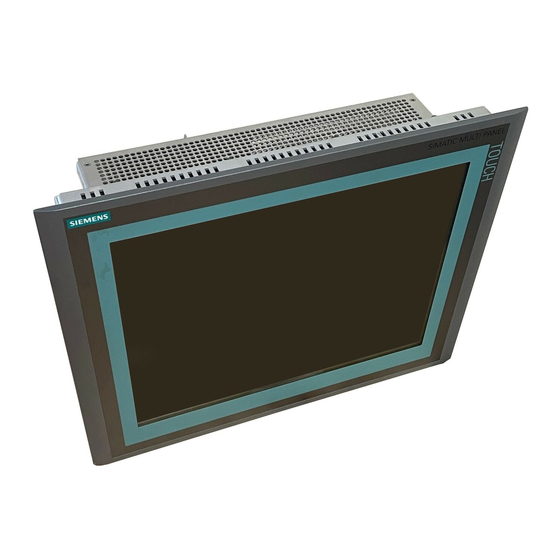
SIMATIC HMI HMI device MP 377 15" Touch daylight readable (WinCC flexible)
SIMATIC HMI
HMI device
MP 377 15" Touch daylight
readable (WinCC flexible)
Operating Instructions (Compact)
This Operating Instruction applies to
the HMI device with the
Order no. 6AV6644-8AB20-0AA0
The following supplement is part of this documentation:
No.
Designation
1
Product Information
04/2009
A5E02532357-01
Drawing number
Edition
A5E02341631-03
06/2009
Preface
______________
Overview
Safety instructions and
______________
approvals
______________
Planning application
Mounting and connecting the
______________
HMI device
______________
Operator controls
Configuring the operating
______________
system
______________
Service and maintenance
______________
Technical specifications
______________
Appendix
______________
Abbreviations
1
2
3
4
5
6
7
8
A
B
Advertisement
Table of Contents

Related Manuals for Siemens Simatic MP 377


Summary of Contents for Siemens Simatic MP 377
- Page 1 SIMATIC HMI HMI device MP 377 15" Touch daylight readable (WinCC flexible) Preface ______________ Overview Safety instructions and ______________ approvals SIMATIC HMI ______________ Planning application HMI device Mounting and connecting the ______________ MP 377 15" Touch daylight HMI device readable (WinCC flexible) ______________ Operator controls Operating Instructions (Compact)
- Page 2 Note the following: WARNING Siemens products may only be used for the applications described in the catalog and in the relevant technical documentation. If products and components from other manufacturers are used, these must be recommended or approved by Siemens. Proper transport, storage, installation, assembly, commissioning, operation and maintenance are required to ensure that the products operate safely and without any problems.
-
Page 3: Preface
Preface Purpose of this manual This manual provides information based on the requirements defined by DIN 62079 regarding mechanical engineering documentation. This information relates to the place of use, transport, storage, mounting, use and maintenance. This manual is intended for: ●... - Page 4 Illustrations in this manual This manual contains illustrations of the described devices. The illustrations may differ from devices actually delivered. Trademarks The following designations marked with the symbol ® are registered trademarks of Siemens AG: ● HMI ® ● SIMATIC ®...
- Page 5 Preface Additional information You can find additional information about products described in the manual under "Contact" in the following table: Request Contact Contact persons and office locations "http://www.siemens.com/automation/partner" Additional technical documentation "http://www.automation.siemens.com/simatic/portal/html_7 6/techdoku.htm" Training Center "http://sitrain.automation.siemens.com/sitrain" Technical Support "http://support.automation.siemens.com" Online support request form "http://www.siemens.com/automation/support-request"...
- Page 6 Preface MP 377 15" Touch daylight readable (WinCC flexible) Operating Instructions (Compact), 04/2009, A5E02532357-01...
-
Page 7: Table Of Contents
Table of contents Preface ..............................3 Overview..............................9 Product overview ...........................9 Design ............................11 Scope of delivery .........................13 Service pack..........................13 Safety instructions and approvals ......................15 Validity............................15 Safety notes ..........................15 Standards, certificates and approvals..................16 Notes about Usage ........................19 Electro-Magnetic Compatibility ....................22 Planning application.......................... - Page 8 Table of contents Service and maintenance ........................51 Maintenance and Care........................ 51 Repair............................52 Technical specifications........................... 53 Dimension drawing........................53 Technical Specifications......................54 Ambient conditions........................56 Transport and Storage Conditions ....................57 Appendix..............................59 ESD guideline ..........................59 Configure "SetBrightness" function..................... 61 A.2.1 Overview .............................
-
Page 9: Overview
Overview Product overview The SIMATIC HMI device "MP 377 15" Touch daylight readable" offers a special display and touch technology. This technology offers a brighter display that lets operators monitor and operate even under very bright light conditions. Good readability is ensured even in direct sunlight due to the transflective properties of the display. - Page 10 Overview 1.1 Product overview Advantages of the MP 377 15" Touch daylight readable ● Device front is suitable for rough environmental conditions – Front frame made of aluminum coated with impact-resistant paint – Decorative foil with UV protection – Hardened glass – Mohs 7 –...
-
Page 11: Design
Overview 1.2 Design Design Front view and side view ① Housing frame ② Front membrane ③ Display/touch screen ④ Protection for memory cards ⑤ Oblong holes for mounting clamps/air vents ⑥ Fans ⑦ Fixing element for strain relief The term "front operating panel" as used in this manual corresponds to the front view with operating elements. - Page 12 Overview 1.2 Design Rear view ① Rating plate ② Protection for memory cards ③ Mounting seal ④ DIP switch ⑤ Mains terminal for power supply of fans ⑥ Fixing elements for strain relief MP 377 15" Touch daylight readable (WinCC flexible) Operating Instructions (Compact), 04/2009, A5E02532357-01...
-
Page 13: Scope Of Delivery
Overview 1.3 Scope of delivery Scope of delivery The following components are included in the scope of delivery: ● An HMI device ● A CD with the following content: – HMI device image for "MP 377 15" Daylight readable" – Installation file "MP377 SetBrightness" for the add-on "SetBrightness" (.msi-Format) –... - Page 14 Overview 1.4 Service pack MP 377 15" Touch daylight readable (WinCC flexible) Operating Instructions (Compact), 04/2009, A5E02532357-01...
-
Page 15: Safety Instructions And Approvals
Safety instructions and approvals Validity This manual includes important information on the operation of the MP 377 15" Touch daylight readable in potentially explosive atmospheres of zones 2 and 22. WARNING Read all sections of this manual. Please observe all safety guidelines contained within the sections. -
Page 16: Standards, Certificates And Approvals
Ex tD A22 IP6X T xx °C x ... Temperature values, see design examination certificate The design examination certificate is available at the following Internet address: "http://support.automation.siemens.com" CE approval The HMI device meets the general and safety-related requirements of the following EC... - Page 17 Safety instructions and approvals 2.3 Standards, certificates and approvals EC Declaration of Conformity The EC Declarations of Conformity are available to the relevant authorities at the following address: Siemens AG Industry Sector I IA AS R&D ST PO Box 1963 92209 Amberg...
- Page 18 The HMI device meets the requirements and criteria conforming to IEC 61131-2, Programmable Logic Controllers, Part 2, equipment requirements and testing. Requesting certificates Copies of the certificates and reports can be requested from the following address: Siemens AG Industry Sector I IA AS R&D ST PO Box 1963...
-
Page 19: Notes About Usage
If an HMI device is operated in potentially explosive atmospheres of zone 22, pay attention to the product information "Use in potentially explosive atmospheres of zones 2 and 22." The product information is available at the following Internet address: "http://support.automation.siemens.com/WW/view/en/291285" MP 377 15" Touch daylight readable (WinCC flexible) Operating Instructions (Compact), 04/2009, A5E02532357-01... - Page 20 Safety instructions and approvals 2.4 Notes about Usage WARNING Personal injury and damage to property Personal injury and property damage can occur in potentially explosive atmospheres if an electric plug is disconnected from the HMI device while the system is in operation. In potentially explosive atmospheres, always turn off power to the HMI device before disconnecting any connectors.
- Page 21 Safety instructions and approvals 2.4 Notes about Usage Operating conditions for Zones 2 and 22 The following operating conditions apply for Zones 2 and 22: ● The HMI device must be installed in a control cabinet. The control cabinet must meet the following in accordance with EN 60529: –...
-
Page 22: Electro-Magnetic Compatibility
Approved HMI device The HMI devices with approval for operation in potentially explosive atmospheres are listed at the following Internet address: "http://support.automation.siemens.com/WW/view/en/291285" Electro-Magnetic Compatibility Introduction The HMI device fulfils, among other things, the requirements of the EMC laws pertaining to the European domestic market. - Page 23 Safety instructions and approvals 2.5 Electro-Magnetic Compatibility Sinusoidal disturbance The table below shows the EMC properties of the modules with respect to sinusoidal interference. This requires the HMI device to meet the specifications and directives for electrical installation. Sinusoidal interference Test values Corresponds to severity...
- Page 24 Safety instructions and approvals 2.5 Electro-Magnetic Compatibility MP 377 15" Touch daylight readable (WinCC flexible) Operating Instructions (Compact), 04/2009, A5E02532357-01...
-
Page 25: Planning Application
Planning application General information Proper transport and storage, installation and assembly as well as careful operation and maintenance are required to ensure trouble-free and safe operation of the HMI device. The warranty for the HMI device will be deemed void if these stipulations are not heeded. Mounting positions and type of fixation Permitted mounting positions The HMI device is designed for mounting in stationary cabinets, for example for mobile... -
Page 26: Preparation For Mounting
Planning application 3.3 Preparation for mounting Preparation for mounting Selecting the mounting location for the HMI device Points to observe when selecting the mounting location: ● Position the HMI device so that it is not subjected to direct sunlight. The display was designed for operation in direct sunlight. ●... - Page 27 Planning application 3.3 Preparation for mounting Maintaining clearances The HMI device must be installed with the following clearances: Where Clearance Observe a clearance above and below the mounting cutout for 50 mm ventilation of Right and left of the mounting cut-out for the mounting clamps 18 mm At the rear in addition to the mounting depth of the HMI device at ≥...
- Page 28 Planning application 3.3 Preparation for mounting MP 377 15" Touch daylight readable (WinCC flexible) Operating Instructions (Compact), 04/2009, A5E02532357-01...
-
Page 29: Mounting And Connecting The Hmi Device
Mounting and connecting the HMI device Mounting the HMI device Requirement These are the requirements: ● All packaging components and protective foils should be removed from the HMI device. ● The HMI device comes equipped with a mounting seal. ● 10 mounting clamps from the accessory kit ●... - Page 30 Mounting and connecting the HMI device 4.1 Mounting the HMI device Procedure CAUTION Degree of protection on front at risk If the mounting seal is damaged, if it does not fully rest in the groove for the mounting seal or if the ends of the mounting seal do not meet in the groove, then the degree of protection is not guaranteed for the front of the HMI device.
-
Page 31: Connecting The Hmi Device
● The HMI device must be mounted according to the specifications of these operating instructions. ● Always use shielded standard cables. Standard cables are also available at the following Internet address: "http://mall.automation.siemens.com" There you select "Products". Connection sequence NOTICE Observe the connection sequence Failure to do so may result in damage to the HMI device. - Page 32 Mounting and connecting the HMI device 4.2 Connecting the HMI device Interfaces The following figure shows the interfaces of the HMI device. ① Connection for power supply of fans ② Connection for power supply of HMI device ③ RS 422 / RS 485 port X10/IF 1B ④...
-
Page 33: Connecting The Fan
Mounting and connecting the HMI device 4.2 Connecting the HMI device 4.2.2 Connecting the Fan The fans have the following purpose: ● To dissipate heat generated by the higher power loss compared to "MP 377". ● To ensure proper cooling in case of inclined installation. The fans are designed for continuous operation. - Page 34 Mounting and connecting the HMI device 4.2 Connecting the HMI device Note Applies to non-isolated plant configurations: Connect the "GND" terminal of the 24 VDC power supply to the equipotential bonding. You should always select a central point of termination. Requirement These are the requirements: ●...
-
Page 35: Switching On And Testing The Hmi Device
Mounting and connecting the HMI device 4.2 Connecting the HMI device 1. Connect the wires on the mains terminal as shown in the following illustration. Ensure that the wires are connected properly to the correct terminals. Refer to the label of the sockets on the rear of the HMI device. - Page 36 Mounting and connecting the HMI device 4.2 Connecting the HMI device MP 377 15" Touch daylight readable (WinCC flexible) Operating Instructions (Compact), 04/2009, A5E02532357-01...
-
Page 37: Operator Controls
Operator controls Front operator controls The MP 377 15" Touch daylight readable comes equipped with a transflective display with higher contrast. This makes objects on the display visible even in direct sunlight and easy to monitor and operate. The comprehensive dimming range with 256 settings makes for fatigue-free reading in very bright and very dark ambient lighting. -
Page 38: Removing The Memory Card Cover
Operator controls 5.2 Removing the memory card cover Removing the memory card cover Introduction Installed memory cards are secured and protected in their slots by a slot cover. Note Please observe the notes on the memory card in the operating instructions "MP 377". Procedure Proceed as follows: 1. -
Page 39: Configuring The Operating System
Configuring the operating system Introduction For a description on how to configure the operating system, see the section "Configuring the operating system" in the operating instructions "MP 377 (WinCC flexible)" as of edition 09/2007. The following section includes the differences and amends the section of the same name in the operating instructions listed above. - Page 40 Configuring the operating system 6.2 Calibrating the touch screen Procedure Note You have to touch the calibration crosshairs and the buttons one after the other in 5 s intervals. Otherwise the "OP Properties" dialog will be displayed again. Proceed as follows: 1.
- Page 41 Configuring the operating system 6.2 Calibrating the touch screen 3. Touch the "Confirm" button. The calibration is saved. The "OP Properties" dialog, "Touch" tab is displayed again. If you do not touch the "Confirm" button within 5 s, your original calibration will be retained. 4.
-
Page 42: Setting The Display Brightness
Configuring the operating system 6.3 Setting the display brightness Setting the display brightness Introduction The brightness of the display can be set in 256 levels. Dimming takes place based on a gradual curve and is perceived by the eye as linear. You change the brightness as follows: ●... - Page 43 Configuring the operating system 6.3 Setting the display brightness Procedure Proceed as follows: 1. Click on the "ADVANCED" button. The following dialog opens: ① Button for entry of value for maximum display brightness ② Value for maximum display brightness ③ Slider control ④...
- Page 44 Configuring the operating system 6.3 Setting the display brightness Note If you do not operate the "Brightness" dialog for 25 seconds, the following message will appear: "You did not operate the dialogue for more than 25 seconds! The brightness was put back to the default value!"...
- Page 45 Configuring the operating system 6.3 Setting the display brightness 6. Set the value for minimum display brightness in the group "Min Brightness". NOTICE Display can no longer be read You can reduce the display brightness to a level that is so low that you cannot see the screen objects in the display in case of poor lighting conditions or darkness.
-
Page 46: Setting The Screen Saver
Configuring the operating system 6.4 Setting the screen saver Setting the screen saver Introduction You can set the following time intervals on the HMI device: ● For the automatic activation of the screen saver ● For automatically turning off the backlighting of the screen When you do not undertake an operation within the configured interval, the configured function will be activated automatically. - Page 47 Configuring the operating system 6.4 Setting the screen saver Requirement These are the requirements: You have opened the Screensaver dialog with the ScreenSaver icon. ① Time interval in minutes until backlighting is turned off ② Period of time in minutes before the screen saver is activated ③...
-
Page 48: Restarting The Hmi Device
Configuring the operating system 6.5 Restarting the HMI device Restarting the HMI device Introduction You can restart the HMI device or reset the factory settings before rebooting. Additional information is available in the section "Reset the factory settings" in the operating instructions "MP 377, edition 09/2007". - Page 49 Configuring the operating system 6.5 Restarting the HMI device Procedure Proceed as follows: 1. Click on the "Reboot" button. The following dialog appears: ① If you run this function, all data which has not been backed up will be lost. Please close all applications before restarting.
- Page 50 Configuring the operating system 6.5 Restarting the HMI device MP 377 15" Touch daylight readable (WinCC flexible) Operating Instructions (Compact), 04/2009, A5E02532357-01...
-
Page 51: Service And Maintenance
Service and maintenance Maintenance and Care Scope of maintenance The HMI device is designed for maintenance-free operation. The scope of maintenance includes: ● Checking fans for proper operation Check fans regularly for proper operation. The fans are not monitored electronically. ●... -
Page 52: Repair
4. Wipe off the edges of the front operating panel. Repair If the unit needs to be repaired, you will have to ship the HMI device to the Return Center in Fürth. The address is: Siemens AG Industry Sector Returns Center Siemensstr. 2 90766 Fürth... -
Page 53: Technical Specifications
Technical specifications Dimension drawing MP 377 15" Touch daylight readable (WinCC flexible) Operating Instructions (Compact), 04/2009, A5E02532357-01... -
Page 54: Technical Specifications
Technical specifications 8.2 Technical Specifications Technical Specifications Weight Weight Approx. 4.6 kg Degree of protection Front IP66 Rear IP20 Display Type LCD TFT Material Glass Glass thickness 3 mm Hardness to Mohs Colors, displayable 16 million Backlighting Half brightness lifetime, typical 50 000 h Display area, active 304.1 mm x 228.1 mm (15") - Page 55 Technical specifications 8.2 Technical Specifications Supply connection HMI device Rated voltage +24 V DC Valid range 19.2 V to 28.8 V (–20 %, +20 %) Transients, maximum permissible 35 V, 500 ms Time between two transients, minimum 50 s Fuse, internal Electronic Current consumption Typical...
-
Page 56: Ambient Conditions
Technical specifications 8.3 Ambient conditions Ambient conditions Mechanical ambient conditions The following table provides information on the type and scope of tests for mechanical ambient conditions. Test Test Standard Release values Vibration IEC 60068, Part 2–6 (sinusoidal) 10 Hz ≤ f ≤ 58 Hz constant amplitude: 0.075 mm 58 Hz ≤... -
Page 57: Transport And Storage Conditions
Technical specifications 8.4 Transport and Storage Conditions Transport and Storage Conditions Climatic transport and storage conditions The transport and storage conditions of this HMI device exceed requirements conforming to IEC 61131-2. The following specifications apply to the transport and storage of an HMI device in its original packing. - Page 58 Technical specifications 8.4 Transport and Storage Conditions MP 377 15" Touch daylight readable (WinCC flexible) Operating Instructions (Compact), 04/2009, A5E02532357-01...
-
Page 59: Appendix
Appendix ESD guideline What does ESD mean? All electronic modules are equipped with large-scale integrated ICs or components. Due to their design, these electronic components are highly sensitive to overvoltage and thus to the discharge of static electricity. Such electronic components are labeled as Electrostatic Sensitive Device. - Page 60 Appendix A.1 ESD guideline Anyone who is not connected to the electrical potential of their surroundings is subject to electrostatic charge. The following figure indicates the maximum electrostatic charge anyone is subjected to when coming into contact with the materials shown. These values correspond to IEC 801-2 specifications.
-
Page 61: Configure "Setbrightness" Function
Appendix A.2 Configure "SetBrightness" function Configure "SetBrightness" function A.2.1 Overview The add-on "SetBrightness" expands the configuration options under WinCC flexible 2008 and is also available for the MP 377 15" Touch daylight readable. The "SetBrightness" function gives you the option to alter the display brightness of several HMI devices at the same time, for example. -
Page 62: Add-On "Setbrightness
Appendix A.2 Configure "SetBrightness" function A.2.2 Add-on "SetBrightness" Introduction This section describes the configuration of the function "SetBrightness" based on an example, how to set the brightness of displays with a potentiomenter "externally" for a panel and "centrally" in a control room. The following picture shows the structure of such a system. The following section describes how to configure "SetBrightness"... - Page 63 Appendix A.2 Configure "SetBrightness" function Procedure Proceed as follows: 1. Add an operator control to the project. 2. Open the properties of the operator control. 3. Select "Events". 4. Select "System functions > Brightness > SetBrightness" from the function list. "SetBrightness"...
- Page 64 Appendix A.2 Configure "SetBrightness" function MP 377 15" Touch daylight readable (WinCC flexible) Operating Instructions (Compact), 04/2009, A5E02532357-01...
-
Page 65: Abbreviations
Abbreviations Code of Federal Regulations Canadian Standards Association Direct Current German Institute for Standardization Det Norske Veritas Distributed I/O European Union Components and modules endangered by electrostatic discharge Electromagnetic Compatibility European standard EPDM Ethylene Propylene Diene Monomer Engineering System Components and modules endangered by electrostatic discharge Food and Drug Administration Ground Human Machine Interface... - Page 66 Abbreviations MP 377 15" Touch daylight readable (WinCC flexible) Operating Instructions (Compact), 04/2009, A5E02532357-01...
-
Page 67: Glossary
Glossary Degree of protection The degree of protection specifies a standard of electronic equipment for a variety of environmental conditions – and the protection of persons against potential danger when using this equipment. The degree of protection specified by IP differs from the protection class. But both involve protection against touching dangerous electric voltage. - Page 68 Glossary MP 377 15" Touch daylight readable (WinCC flexible) Operating Instructions (Compact), 04/2009, A5E02532357-01...
-
Page 69: Index
Index Climatic Storage conditions, 57 Transport conditions, 57 Configuration graphic 24 VDC supply, 33 Power supply, 33 Connecting Connection sequence, 31 HMI device, 31 Accessory kit, 13 Power supply, 33 Addon Connection sequence, 31 SetBrightness, 13 Contact person, 5 Air flow Conventions, 4 Direction, 35 Ambient conditions... - Page 70 Index Mounting EMC-compliant, 22 High frequency radiation, 15 HMI device, 30 HMI device Mounting cutout, 26 Approved, 22 Dimensions, 26 Connecting, 31 Preparing, 26 EMC-compliant mounting, 22 Mounting position Mounting, 30 HMI device, 25 Mounting position, 25 Mounting seal, 12 Restart, 48 MP 377 15"...
- Page 71 Index Supply connection Fans, 55 radiation HMI device, 55 High frequency, 15 Radio interference, 19 Emission, 23 Rating plate, 12 Rear view, 12 Technical specifications Rechargeable battery Degree of protection, 54 Used, 5 Display, 54 Recycling, 5 Fans, 55 Registered trademark, 4 HMI device, 55 Repairs, 52 Input unit, 54...
- Page 72 Index MP 377 15" Touch daylight readable (WinCC flexible) Operating Instructions (Compact), 04/2009, A5E02532357-01...
- Page 73 Weiterführende Informationen zu den im Handbuch beschriebenen Produkten finden Sie unter Kontakt in der folgenden Tabelle: Anforderung Kontakt Vertretungen und Geschäftsstellen http://www.automation.siemens.com/partner Weiterführende technische Dokumentation http://www.automation.siemens.com/simatic/portal/html_00/techdoku.htm Trainingscenter http://sitrain.automation.siemens.com/sitrain/ Technical Support http://support.automation.siemens.com Web-Formular für eine Supportanfrage https://support.automation.siemens.com Service http://www.siemens.com/automation/service © Siemens Ⓟ2009 A5E02341631-03, 06/2009...
- Page 74 Einsatz planen Zulässige Einbaulagen Das Bediengerät ist für den Einbau in Schaltschränke vorgesehen. Das Bediengerät ist für den Einbau im Querformat zugelassen. In der Vertikalen sind folgende Einbaulagen zulässig: ● Senkrecht ● Geneigt zwischen 0° und 90° ● Waagerecht Einsatz im erweiterten Temperaturbereich Das "Temperature Extension Kit"...
- Page 75 Bediengerät einbauen Voraussetzung Folgendes wird vorausgesetzt: ● Alle Verpackungsbestandteile und Schutzfolien am Bediengerät wurden entfernt. ● Am Bediengerät ist die Einbaudichtung vorhanden. ● 10 Spannklemmen aus dem Beipack ● Der Einbauausschnitt ist gratfrei. Damit die Schutzart an der Vorderseite des Bediengeräts erreicht wird, ist es erforderlich, dass die nachfolgend aufgeführten Positionen für die Spannklemmen eingehalten werden.
- Page 76 Hinweis Bauen Sie das Bediengerät nur nach den Vorgaben des vorliegenden Handbuchs ein. Ziehen Sie die Gewindestifte der Spannklemmen nur so weit an, bis das Bediengerät bündig an der Einbaufront des Schaltschranks anliegt. Alternativ können Sie die Spannklemmen mit einem Drehmoment max. 0,2 Nm anziehen. Gehen Sie wie folgt vor: 1.
- Page 77 Bedienung des kapazitiven Touch-Screen So bedienen Sie den kapazitiven Touch-Screen richtig: ● Berühren Sie den Touch-Screen ausschliesslich mit der Fingerspitze. Der Finger kann durch einen dünnen Handschuh, z. B. einen sterilen Handschuh, geschützt sein. ● Berühren Sie den Touch-Screen senkrecht zur Oberfläche. ●...
-
Page 78: Touch-Screen Kalibrieren
Touch-Screen kalibrieren Einleitung In Abhängigkeit von Einbaulage und Betrachtungswinkel kann beim Touch-Screen eine Parallaxe auftreten. Um daraus resultierende Bedienungsfehler zu vermeiden, kalibrieren Sie den Touch-Screen während der Inbetriebnahme oder während des laufenden Betriebs. Die Kalibrierung des Touch-Screen erfolgt über 25 Kalibrierpunkte. Dadurch ist eine sehr genaue Kalibrierung möglich. Voraussetzung Sie haben mit dem Symbol "OP"... - Page 79 Gehen Sie wie folgt vor: 1. Betätigen Sie die Schaltfläche "Recalibrate". Der erste Kalibrierpfeil wird auf dem Display angezeigt. 2. Berühren Sie kurzzeitig und innerhalb von fünf Sekunden genau die Spitze des Kalibrierpfeils ①. Mit einem grünen Haken wird die Kalibrierung an dieser Stelle quittiert und ein weiterer Kalibrierpfeil wird angezeigt. 3.
- Page 80 Verwenden Sie zur Projektierung des Bediengeräts ausschliesslich die Software WinCC flexible 2008 SP1. Hinweis Unterstützung von Direkttasten Das Bediengerät wird in der ersten Lieferstufe ohne Unterstützung von Direkttasten geliefert. Siemens AG Industry Sector Postfach 48 48 90026 NÜRNBERG MP 377 15" Touch daylight readable MP 377 15"...
- Page 81 You can find additional information about products described in the manual under "Contact" in the following table: Request Contact Contact persons and office locations http://www.automation.siemens.com/partner Additional technical documentation http://www.automation.siemens.com/simatic/portal/html_76/techdoku.htm Training center http://sitrain.automation.siemens.com/sitrain/ Technical support http://support.automation.siemens.com Online support request form http://www.siemens.com/automation/support-request Service http://www.siemens.com/automation/service © Siemens Ⓟ2009 A5E02341631-03, 06/2009...
- Page 82 Planning application Permitted mounting positions The HMI device is designed for mounting in control cabinets: The HMI device is approved for horizontal mounting. The following vertical mounting positions are permissible: ● Vertical ● Inclined at an angle between 0° and 90° ●...
- Page 83 Mounting the HMI device Requirement These are the requirements: ● All packaging components and protective foils should be removed from the HMI device. ● The HMI device comes equipped with a mounting seal. ● 10 mounting clamps from the accessory kit ●...
-
Page 84: Operating The Touch Screen
Note Always mount the HMI device according to the instructions in this manual. Tighten the threaded pins of the mounting clamps until the HMI device is flush with the front of the control cabinet. You have the option to tighten the mounting clamps with a maximum torque of 0.2 Nm. Proceed as follows: 1. - Page 85 Operation of the capacitive touch screen To operate the capacitive touch screen properly, follow these steps: ● Touch the touch screen only with the fingertips. The finger can be protected by a thin glove, such as a sterile glove. ● Touch the touch screen vertically to the surface. ●...
- Page 86 Calibrating the touch screen Introduction Depending on the mounting position and viewing angle, it is possible that parallax may occur when operating the touch screen. To prevent any resulting operating errors, you may need to calibrate the touch screen during the startup phase or while in runtime.
- Page 87 Proceed as follows: 1. Click on the "Recalibrate" button. The first calibration arrow appears on the display. 2. Touch it briefly and within five seconds exactly on the tip of the calibration arrow ①. Confirm the calibration with a green check mark at this location; the next calibration crosshairs will be displayed. 3.
- Page 88 To configure the HMI device, use only the WinCC flexible 2008 SP1 software. Note Support of direct keys The HMI device will be supplied in the first delivery stage without support of direct keys. Siemens AG Industry Sector Postfach 48 48 90026 NÜRNBERG MP 377 15"...