
Related Manuals for Mitsubishi Electric FR-F720-00046


Summary of Contents for Mitsubishi Electric FR-F720-00046
-
Page 1: Instruction Manual
INVERTER INSTRUCTION MANUAL FR-F720-00046 to 04750-NA FR-F740-00023 to 12120-NA OUTLINE WIRING PRECAUTIONS FOR USE OF THE INVERTER PARAMETERS PROTECTIVE FUNCTIONS PRECAUTIONS FOR MAINTENANCE AND INSPECTION SPECIFICATIONS... - Page 2 Thank you for choosing this Mitsubishi Inverter. This Instruction Manual provides instructions for advanced use of the FR-F700 series inverters. Incorrect handling might cause an unexpected fault. Before using the inverter, always read this instruction manual and the installation guideline [IB-0600218ENG] packed with the product carefully to use the equipment to its optimum. 2.
- Page 3 CAUTION CAUTION (2) Wiring (5) Emergency stop • Do not install a power factor correction capacitor, surge • A safety backup such as an emergency brake must be suppressor or capacitor type filter on the inverter output side. provided to prevent hazardous condition to the machine and These devices on the inverter output side may be overheated equipment in case of inverter failure.
-
Page 4: Table Of Contents
CONTENTS OUTLINE Product checking and parts identification ............2 Inverter and peripheral devices ................3 1.2.1 Peripheral devices ........................4 Method of removal and reinstallation of the front cover........6 Installation of the inverter and enclosure design ..........8 1.4.1 Inverter installation environment.................... - Page 5 EMC and leakage currents ................46 3.1.1 Leakage currents and countermeasures ................. 46 3.1.2 EMC measures ........................48 3.1.3 Power supply harmonics ......................50 Installation of a reactor ..................51 Power-off and magnetic contactor (MC) ............51 Inverter-driven 400V class motor ..............52 Precautions for use of the inverter ..............
- Page 6 Setting of acceleration/deceleration time and acceleration/deceleration pattern..............96 4.7.1 Setting of the acceleration and deceleration time (Pr.7, Pr.8, Pr.20, Pr.21, Pr.44, Pr.45)..96 4.7.2 Starting frequency and start-time hold function (Pr.13, Pr.571) ..........98 4.7.3 Acceleration/deceleration pattern (Pr.29, Pr.140 to Pr.143) ........... 99 Selection and protection of a motor .............
- Page 7 4.14.1 Energy saving control and Optimum excitation control (Pr. 60) ........... 153 4.14.2 Energy saving monitor (Pr. 891 to Pr. 899) ................154 4.15 Motor noise, EMI measures, mechanical resonance ........159 4.15.1 PWM carrier frequency and Soft-PWM control (Pr. 72, Pr. 240, Pr. 260) ......159 4.15.2 Speed smoothing control (Pr.
- Page 8 4.21.4 Current average value monitor signal (Pr. 555 to Pr. 557) ........... 259 4.21.5 Free parameter (Pr. 888, Pr. 889) ..................261 4.22 Setting from the parameter unit, operation panel........262 4.22.1 PU display language selection (Pr. 145) ................262 4.22.2 Operation panel frequency setting/key lock selection (Pr.
- Page 9 6.1.2 Periodic inspection ........................ 294 6.1.3 Daily and periodic inspection ....................295 6.1.4 Display of the life of the inverter parts ................... 296 6.1.5 Checking the inverter and converter modules ............... 296 6.1.6 Cleaning ..........................297 6.1.7 Replacement of parts ......................297 6.1.8 Inverter replacement......................
-
Page 10: Outline
OUTLINE This chapter describes the basic "OUTLINE" for use of this product. Always read the instructions before using the equipment. 1.1 Product checking and parts identification....2 1.2 Inverter and peripheral devices .......3 1.3 Method of removal and reinstallation of the front cover ...............6 1.4 Installation of the inverter and enclosure design ..8 <Abbreviations>... -
Page 11: Product Checking And Parts Identification
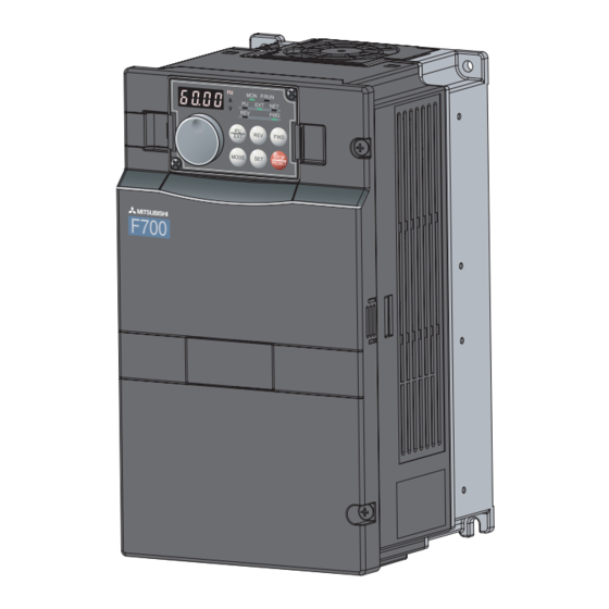
Product checking and parts identification 1.1 Product checking and parts identification Unpack the inverter and check the capacity plate on the front cover and the rating plate on the inverter side face to ensure that the product agrees with your order and the inverter is intact. •... -
Page 12: Inverter And Peripheral Devices
Inverter and peripheral devices 1.2 Inverter and peripheral devices Three-phase AC power supply Inverter Programmable controller Use within the permissible power supply (FR-F700) specifications of the inverter. (Refer to page 308) The life of the inverter is influenced by surrounding air temperature. -
Page 13: Peripheral Devices
Output Contactor Applicable Inverter Model (kW(HP)) Without reactor With reactor Without reactor With reactor connection connection connection connection 0.75 (1) FR-F720-00046-NA 30AF 10A 30AF 10A S-N10 S-N10 1.5 (2) FR-F720-00077-NA 30AF 15A 30AF 15A S-N10 S-N10 2.2 (3) FR-F720-00105-NA 30AF 20A... - Page 14 Inverter and peripheral devices 400V class Motor Input Side Magnetic Breaker Selection Output Contactor Applicable Inverter Model (kW(HP)) Without reactor With reactor Without reactor With reactor connection connection connection connection 0.75 (1) FR-F740-00023-NA 30AF 5A 30AF 5A S-N10 S-N10 1.5 (2) FR-F740-00038-NA 30AF 10A 30AF 10A...
-
Page 15: Method Of Removal And Reinstallation Of The
Method of removal and reinstallation of the front cover 1.3 Method of removal and reinstallation of the front cover •Removal of the operation panel 1) Loosen the two screws on the operation panel. 2) Push the left and right hooks of the operation panel (These screws cannot be removed.) and pull the operation panel toward you to remove. - Page 16 Method of removal and reinstallation of the front cover FR-F720-01540-NA or more, FR-F740-00770-NA or more • Removal 1) Remove installation screws on 2) Loosen the installation 3) Pull the front cover 2 toward you to the front cover 1 to remove the screws of the front cover 2.
-
Page 17: Installation Of The Inverter And Enclosure Design
Installation of the inverter and enclosure design 1.4 Installation of the inverter and enclosure design When an inverter enclosure is to be designed and manufactured, heat generated by contained equipment, etc., the environment of an operating place, and others must be fully considered to determine the enclosure structure, size and equipment layout. -
Page 18: Enclosure Design
Installation of the inverter and enclosure design (3) Dust, dirt, oil mist Dust and dirt will cause such faults as poor contact of contact points, reduced insulation or reduced cooling effect due to moisture absorption of accumulated dust and dirt, and in-enclosure tempearture rise due to clogged filter. In the atmosphere where conductive powder floats, dust and dirt will cause such faults as malfunction, deteriorated insulation and short circuit in a short time. -
Page 19: Cooling System Types For Inverter Enclosure
Installation of the inverter and enclosure design 1.4.2 Cooling system types for inverter enclosure From the enclosure that contains the inverter, the heat of the inverter and other equipment (transformers, lamps, resistors, etc.) and the incoming heat such as direct sunlight must be dissipated to keep the in-enclosure temperature lower than the permissible temperatures of the in-enclosure equipment including the inverter. - Page 20 Installation of the inverter and enclosure design (2) Clearances around the inverter To ensure ease of heat dissipation and maintenance, leave at least the shown clearances around the inverter. At least the following clearances are required under the inverter as a wiring space, and above the inverter as a heat dissipation space. (front) Surrounding air temperature and humidity Clearances...
- Page 21 MEMO...
-
Page 22: Wiring
WIRING This chapter explains the basic "WIRING" for use of this product. Always read the instructions before using the equipment. 2.1 Wiring ..............14 2.2 Main circuit terminal specifications......16 2.3 Control circuit specifications........27 2.4 Connection of stand-alone option units ....36... -
Page 23: Wiring
Wiring 2.1 Wiring 2.1.1 Terminal connection diagram Resistor unit DC reactor (FR-HEL) *6. A CN8 (for MT-BU5) connector is Sink logic (Option) Be sure to connect the DC reactor provided for the FR-F720-03160 supplied with the FR-F720-03160 Brake unit Main circuit terminal (FR-F740-01800) or more. -
Page 24: Emc Filter
ON/OFF connector The FR-F720-00046 and 00077 are not provided with the EMC filter ON/OFF connector. (Always ON) <How to disconnect the connector> (1) Before removing a front cover, check to make sure that the indication of the inverter operation panel is off, wait for at least 10 minutes after the power supply has been switched off, and check that there are no residual voltage using a tester or the like. -
Page 25: Main Circuit Terminal Specifications
Ground For grounding the inverter chassis. Must be grounded. 2.2.2 Terminal arrangement of the main circuit terminal, power supply and the motor wiring 200V class FR-F720-00046, 00077-NA FR-F720-00105 to 00250-NA Jumper Jumper Screw size (M4) Screw size (M4) R/L1 S/L2 T/L3... - Page 26 Main circuit terminal specifications FR-F720-00340, 00490-NA FR-F720-00630-NA R1/L11 S1/L21 Charge lamp Screw size (M4) Jumper Charge lamp P/+ PR Jumper Jumper Jumper R1/L11 S1/L21 Screw size (M5) Screw size (M5) R/L1 S/L2 T/L3 R/L1 S/L2 T/L3 Power supply Motor Power supply Motor Screw size (M5) * Screw size of terminal...
- Page 27 Main circuit terminal specifications 400V class FR-F740-00023 to 00126-NA FR-F740-00170, 00250-NA Jumper Screw size (M4) R/L1 S/L2 T/L3 Charge lamp Jumper R1/L11 S1/L21 P/+ PR Jumper Jumper R1/L11 S1/L21 Screw size Charge lamp (M4) Screw size (M4) Power Motor supply R/L1 S/L2 T/L3 Power supply Motor...
- Page 28 Main circuit terminal specifications FR-F740-03250 to 04810-NA FR-F740-05470 to 12120-NA R1/L11 S1/L21 Screw size (M4) R1/L11 S1/L21 Screw size (M4) Charge lamp Charge lamp Jumper Jumper Screw size (03250/03610: M10 04320/04810: M12) R/L1 S/L2 T/L3 N/- Screw size (M12) R/L1 S/L2 T/L3 N/- Screw size (M10) Power supply...
- Page 29 Do not wire without using conduits. Otherwise, the cable sheathes may be scratched by the wiring cover edges, resulting in a short circuit or ground fault. REMARKS ⋅ When using conduits for the FR-F720-00046 and 00077, fix the conduits to the wiring cover after connecting the earth cable to the inverter earth terminal.
-
Page 30: Cables And Wiring Length
U, V, W U, V, W (ground) U, V, W U, V, W (ground) S/L2, S/L2, S/L2, T/L3 T/L3 T/L3 T/L3 cable cable FR-F720-00046 to 00105-NA FR-F720-00167-NA 5.5-4 5.5-4 FR-F720-00250-NA 5.5-4 5.5-4 FR-F720-00340-NA 14-5 FR-F720-00490-NA 14-5 14-5 FR-F720-00630-NA 22-5 22-5... - Page 31 Main circuit terminal specifications 400V class (when input power supply is 440V based on the rated current for 110% overload for 1 minute) Crimping Cable Sizes (Compression) Terminal HIV, etc. (mm2) *1 AWG/MCM *2 PVC, etc. (mm2) *3 Tightening Terminal Applicable Inverter Model Screw Size Torque N·m...
- Page 32 Main circuit terminal specifications (2) Notes on grounding Always ground the motor and inverter. 1)Purpose of grounding Generally, an electrical apparatus has an ground terminal, which must be connected to the ground before use. An electrical circuit is usually insulated by an insulating material and encased. However, it is impossible to manufacture an insulating material that can shut off a leakage current completely, and actually, a slight current flow into the case.
- Page 33 Main circuit terminal specifications (3) Total wiring length The overall wiring length for connection of a single motor or multiple motors should be within the value in the table below. Pr. 72 PWM frequency selection Setting FR-F720-00046 FR-F720-00077 FR-F720-00105 or more (carrier frequency)
-
Page 34: When Connecting The Control Circuit And The Main Circuit Separately To The Power Supply
Do not connect the power cable to incorrect terminals. Doing so may damage the inverter. S1/L21 Remove the jumper • FR-F720-00046 to 00250, FR-F740-00023 to 00126 1) Loosen the upper screws. 2) Remove the lower screws. 3) Remove the jumper... - Page 35 Main circuit terminal specifications • FR-F720-00630 (FR-F740-00310) or more 1) Remove the upper screws. 2) Remove the lower screws. L21 Power supply 3) Pull the jumper toward you to terminal block remove. for the control circuit Power supply terminal block 4) Connect the separate power supply for the control circuit R/L1S/L2 T/L3...
-
Page 36: Control Circuit Specifications
Control circuit specifications 2.3 Control circuit specifications 2.3.1 Control circuit terminals indicates that terminal functions can be selected using Pr. 178 to Pr. 196 (I/O terminal function selection) (Refer to page 116.) (1) Input signals Terminal Terminal Rated Description Refer to Symbol Name Specifications... - Page 37 Control circuit specifications Terminal Terminal Rated Description Refer to Symbol Name Specifications 10VDC±0.4V Permissible load When connecting the frequency setting potentiometer at an initial Frequency current 10mA status, connect it to terminal 10. setting power Change the input specifications of terminal 2 when connecting it 5.2VDC±0.2V supply to terminal 10E.
- Page 38 Control circuit specifications (2) Output signals Terminal Terminal Rated Description Refer to Symbol Name Specifications 1 changeover contact output indicates that the inverter Relay output 1 protective function has activated and the output stopped. Contact capacity: (Fault output) Fault: No conduction across B-C (Across A-C Continuity), 230VAC 0.3A Normal: Across B-C Continuity (No conduction across A-C) (Power...
-
Page 39: Changing The Control Logic
Control circuit specifications 2.3.2 Changing the control logic The input signals are set to sink logic (SINK) when shipped from the factory. To change the control logic, the jumper connector on the back of the control circuit terminal block must be moved to the other position. - Page 40 Control circuit specifications 4) Sink logic and source logic ⋅ In sink logic, a signal switches on when a current flows from the corresponding signal input terminal. Terminal SD is common to the contact input signals. Terminal SE is common to the open collector output signals. ⋅...
-
Page 41: Control Circuit Terminal Layout
Control circuit specifications 2.3.3 Control circuit terminal layout Control circuit terminal C2 10E 10 Terminal screw size: M3.5 Tightening torque: 1.2N.m STOP (1) Common terminals of the control circuit (SD, 5, SE) Terminals SD, 5, and SE are all common terminals (0V) for I/O signals and are isolated from each other. Do not earth(ground) these terminals. -
Page 42: Wiring Instructions
Control circuit specifications 2.3.4 Wiring instructions It is recommended to use the cables of 0.75mm gauge for connection to the control circuit terminals. If the cable gauge used is 1.25mm or more, the front cover may be lifted when there are many cables running or the cables are run improperly, resulting in an operation panel contact fault. -
Page 43: When Connecting The Operation Panel Using A Connection Cable
Control circuit specifications 2.3.5 When connecting the operation panel using a connection cable Having an operation panel on the enclosure surface is convenient. With a connection cable, you can mount the operation panel (FR-DU07) to the enclosure surface, and connect it to the inverter. Parameter unit connection cable (FR-CB2 )(option) -
Page 44: Terminal Block
Control circuit specifications 2.3.6 RS-485 terminal block ⋅ Conforming standard: EIA-485(RS-485) ⋅ Transmission format: Multidrop link OPEN ⋅ Communication speed: MAX 38400bps ⋅ Overall length: 500m Terminating resistor switch ⋅ Connection cable:Twisted pair cable Factory-set to "OPEN". (4 pairs) Set only the terminating resistor switch of the remotest inverter to the "100Ω"... -
Page 45: Connection Of Stand-Alone Option Units
Connection of stand-alone option units 2.4 Connection of stand-alone option units The inverter accepts a variety of stand-alone option units as required. Incorrect connection will cause inverter damage or accident. Connect and operate the option unit carefully in accordance with the corresponding option unit manual. 2.4.1 Connection of the brake unit (FR-BU2) Connect the brake unit (FR-BU2) as shown below to improve the braking capability at deceleration. - Page 46 Connection of stand-alone option units (2) FR-BR-(H) connection example with resistor unit FR-BR MCCB Motor R/L1 Three phase AC S/L2 power supply T/L3 FR-BU2 Inverter 5m or less Connect the inverter terminals (P/+, N/-) and brake unit (FR-BU2) terminals so that their terminal names match with each other. (Incorrect connection will damage the inverter and brake unit.) When the power supply is 400V class, install a step-down transformer.
-
Page 47: Connection Of The Brake Unit (Fr-Bu/Mt-Bu5)
Connection of stand-alone option units 2.4.2 Connection of the brake unit (FR-BU/MT-BU5) When connecting the brake unit (FR-BU(H)/MT-BU5) to improve the brake capability at deceleration, make connection as shown below. (1) Connection with the FR-BU (FR-F720-02330 (FR-F740-01160) or less) FR-BR MCCB Motor R/L1... - Page 48 Connection of stand-alone option units (2) Connection with the MT-BU5 (FR-F720-03160 (FR-F740-01800) or more) After making sure that the wiring is correct, set "1" in Pr.30 Regenerative function selection. (Refer to page 108) MCCB Motor R/L1 Three-phase AC power S/L2 supply T/L3 5m(16.4feet)
-
Page 49: Connection Of The Brake Unit (Bu Type)
Connection of stand-alone option units 2.4.3 Connection of the brake unit (BU type) Connect the brake unit (BU type) correctly as shown below. Incorrect connection will damage the inverter. Remove the jumper across terminals HB-PC and terminals TB-HC of the brake unit and fit it to across terminals PC-TB. Inverter MCCB Motor... - Page 50 Connection of stand-alone option units (2) Connection with the MT-HC (FR-F720-03160 (FR-F740-01800) or more) MT-HCL01 MT-HCB MT-HCL02 MT-HC Inverter MCCB Motor Three-phase R/L1 AC power S/L2 supply T/L3 R1 S1 MT-HCTR Isolated transformer Remove the jumper across terminals R-R1, S-S1 of the inverter, and connect the control circuit power supply to the R1 and S1 terminals.
-
Page 51: Connection Of The Power Regeneration Common Converter (Fr-Cv)(Fr-F720-02330 (Fr-F740- 01160) Or Less)
Connection of stand-alone option units 2.4.5 Connection of the power regeneration common converter (FR-CV)(FR-F720- 02330 (FR-F740-01160) or less) When connecting the power regeneration common converter (FR-CV), make connection so that the inverter terminals (P/+, N/-) and the terminal symbols of the power regeneration common converter (FR-CV) are the same. After making sure that the wiring is correct, set "2"... -
Page 52: Connection Of The Power Regeneration Converter (Mt-Rc) (Fr-F720-03160 (Fr-F740-01800) Or More)
Connection of stand-alone option units 2.4.6 Connection of the power regeneration converter (MT-RC) (FR-F720-03160 (FR- F740-01800) or more) When connecting a power regeneration converter (MT-RC), perform wiring securely as shown below. Incorrect connection will damage the regeneration converter and inverter. After connecting securely, set "1" in Pr. - Page 53 MEMO...
-
Page 54: Precautions For Use Of The Inverter
PRECAUTIONS FOR USE OF THE INVERTER This chapter explains the "PRECAUTIONS FOR USE OF THE INVERTER" for use of this product. Always read the instructions before using the equipment. 3.1 EMC and leakage currents........46 3.2 Installation of a reactor ..........51 3.3 Power-off and magnetic contactor (MC)....51 3.4 Inverter-driven 400V class motor ......52 3.5 Precautions for use of the inverter ......53... -
Page 55: Emc And Leakage Currents
EMC and leakage currents 3.1 EMC and leakage currents 3.1.1 Leakage currents and countermeasures Capacitances exist between the inverter I/O cables, other cables and earth and in the motor, through which a leakage current flows. Since its value depends on the static capacitances, carrier frequency, etc., low acoustic noise operation at the increased carrier frequency of the inverter will increase the leakage current. - Page 56 22(1)* Phase grounding Earthed-neutral system *For the FR-F720-00046 and FR-F720-00077, the EMC filter is always valid. The leakage current is 1mA. CAUTION ⋅ Install the earth leakage circuit breaker (ELB) on the input side of the inverter. ⋅ In the connection earthed-neutral system, the sensitivity current is blunt against an ground fault in the inverter output side.
-
Page 57: Emc Measures
EMC and leakage currents 3.1.2 EMC measures Some electromagnetic noises enter the inverter to malfunction it and others are radiated by the inverter to malfunction peripheral devices. Though the inverter is designed to have high immunity performance, it handles low-level signals, so it requires the following basic techniques. - Page 58 EMC and leakage currents Propagation Path Measures When devices that handle low-level signals and are liable to malfunction due to electromagnetic noises, e.g. instruments, receivers and sensors, are contained in the enclosure that contains the inverter or when their signal cables are run near the inverter, the devices may be malfunctioned by air-propagated electromagnetic noises.
-
Page 59: Power Supply Harmonics
EMC and leakage currents 3.1.3 Power supply harmonics The inverter may generate power supply harmonics from its converter circuit to affect the power generator, power capacitor etc. Power supply harmonics are different from noise and leakage currents in source, frequency band and transmission path. -
Page 60: Installation Of A Reactor
Installation of a reactor 3.2 Installation of a reactor When the inverter is connected near a large-capacity power transformer (1000kVA or more) or when a power capacitor is to be switched over, an excessive peak current may flow in the power input circuit, damaging the converter circuit. To prevent this, always install the AC reactor (FR-HAL) AC reactor (kVA) -
Page 61: Inverter-Driven 400V Class Motor
Inverter-driven 400V class motor 3.4 Inverter-driven 400V class motor In the PWM type inverter, a surge voltage attributable to wiring constants is generated at the motor terminals. Especially for a 400V class motor, the surge voltage may deteriorate the insulation. When the 400V class motor is driven by the inverter, consider the following measures: Measures It is recommended to take either of the following measures:... -
Page 62: Precautions For Use Of The Inverter
Precautions for use of the inverter 3.5 Precautions for use of the inverter The FR-F700 series is a highly reliable product, but incorrect peripheral circuit making or operation/handling method may shorten the product life or damage the product. Before starting operation, always recheck the following items. (1) Use crimping terminals with insulation sleeve to wire the power supply and motor. - Page 63 Precautions for use of the inverter (13) If the machine must not be restarted when power is restored after a power failure, provide a magnetic contactor in the inverter's input side and also make up a sequence which will not switch on the start signal. If the start signal (start switch) remains on after a power failure, the inverter will automatically restart as soon as the power is restored.
-
Page 64: Failsafe Of The System Which Uses The Inverter
Failsafe of the system which uses the inverter 3.6 Failsafe of the system which uses the inverter When a fault occurs, the inverter trips to output a fault signal. However, a fault output signal may not be output at an inverter fault occurrence when the detection circuit or output circuit fails, etc. - Page 65 Failsafe of the system which uses the inverter 4) Checking the motor operating status by the start signal input to the inverter and inverter output current detection signal. The output current detection signal (Y12 signal) is output when the inverter operates and currents flows in the motor. Check if Y12 signal is output when inputting the start signal to the inverter (forward signal is STF signal and reverse signal is STR signal).
-
Page 66: Parameters
4 PARAMETERS This chapter explains the "PARAMETERS" for use of this product. Always read the instructions before using the equipment. -
Page 67: Operation Panel (Fr-Du07)
Operation panel (FR-DU07) 4.1 Operation panel (FR-DU07) 4.1.1 Parts of the operation panel (FR-DU07) Operation mode indication PU: Lit to indicate PU operation mode. EXT: Lit to indicate External operation mode. NET: Lit to indicate Network operation mode. Rotation direction indication FWD: Lit during forward rotation REV: Lit during reverse rotation Forward/reverse operation... -
Page 68: Basic Operation (Factory Setting)
Operation panel (FR-DU07) 4.1.2 Basic operation (factory setting) Operation mode switchover At powering on (External operation mode) PU Jog operation mode (Refer to page 60) (Example) Value change and frequency flicker. PU operation mode Frequency setting has been (output frequency monitor) written and completed!! Output current monitor Output voltage monitor... -
Page 69: Changing The Parameter Setting Value
Operation panel (FR-DU07) 4.1.3 Changing the parameter setting value Changing example Change the Pr. 1 Maximum frequency . Operation Display Screen at powering on The monitor display appears. PU indication is lit. Press to choose the PU operation mode. The parameter Press to choose the parameter number read... -
Page 70: Parameter List
Parameter list 4.2 Parameter list 4.2.1 Parameter list In the initial setting, only the simple mode parameters are displayed. Set Pr. 160 User group read selection as required. Initial Setting Parameter Name Remarks Value Range 9999 Only the simple mode parameters can be displayed. Simple mode and extended mode parameters can be User group read displayed. - Page 71 Parameter list Minimum Refer Initial Customer Name Setting Range Setting Function Parameters Value Setting Increments Page Acceleration/deceleration reference 1 to 400Hz 0.01Hz 60Hz frequency Acceleration/deceleration time 0, 1 increments Stall prevention operation level 0 to 120%, 9999 0.1% 110% Stall prevention operation level 0 to 150%, 9999 0.1% 9999...
- Page 72 Parameter list Minimum Refer Initial Customer Name Setting Range Setting Function Parameters Value Setting Increments Page 0, 0.1 to 5s, 9999/ Restart coasting time 0.1s 9999 0, 0.1 to 30s, 9999 Restart cushion time 0 to 60s 0.1s ⎯ Remote function selection 0, 1, 2, 3, 11, 12, 13 ⎯...
- Page 73 Parameter list Minimum Refer Initial Customer Name Setting Range Setting Function Parameters Value Setting Increments Page Terminal 2 frequency setting gain ⎯ 0 to 400Hz 0.01Hz 60Hz frequency Terminal 4 frequency setting gain ⎯ 0 to 400Hz 0.01Hz 60Hz frequency PID control automatic switchover 0 to 400Hz, 9999 0.01Hz...
- Page 74 Parameter list Minimum Refer Initial Customer Name Setting Range Setting Function Parameters Value Setting Increments Page ⎯ User group read selection 0, 1, 9999 Frequency setting/key lock operation ⎯ 0, 1, 10, 11 selection Automatic restart after instantaneous 0, 1, 10, 11 power failure selection First cushion time for restart 0 to 20s...
- Page 75 Parameter list Minimum Refer Initial Customer Name Setting Range Setting Function Parameters Value Setting Increments Page RUN terminal function selection 0 to 5, 7, 8, 10 to 19, 25, SU terminal function selection 26, 45 to 48, 64, 70 to 79, 85, 90 to 96, 98, 99, 100 to 105, 107, 108, IPF terminal function selection...
- Page 76 Parameter list Minimum Refer Initial Customer Name Setting Range Setting Function Parameters Value Setting Increments Page Power failure stop selection 0, 1, 2, 21, 22 Subtracted frequency at deceleration 0 to 20Hz 0.01Hz start Subtraction starting frequency 0 to 120Hz, 9999 0.01Hz 60Hz Power-failure deceleration time 1...
- Page 77 Parameter list Minimum Refer Initial Customer Name Setting Range Setting Function Parameters Value Setting Increments Page Protocol selection 0, 1 NET mode operation command 0, 1, 9999 9999 source selection PU mode operation command source 1, 2 selection PID deviation limit 0 to 100.0%, 9999 0.1% 9999...
- Page 78 Parameter list Minimum Refer Initial Customer Name Setting Range Setting Function Parameters Value Setting Increments Page Regeneration avoidance operation 0, 1, 2 selection Regeneration avoidance operation 380V/ 300 to 800V 0.1V level 760VDC Regeneration avoidance at deceleration 0 to 5 detection sensitivity Regeneration avoidance 0 to 10Hz, 9999...
- Page 79 Parameter list Minimum Refer Initial Customer Name Setting Range Setting Function Parameters Value Setting Increments Page Current output bias signal 0 to 100% 0.1% (930) Current output bias current 0 to 100% 0.1% (930) Current output gain signal 0 to 100% 0.1% 100% (931)
- Page 80 Parameters according to purposes Adjustment of the output torque (current) of the motor 4.3.1 Manual torque boost (Pr. 0, Pr. 46) ........................... 73 4.3.2 Simple magnetic flux vector control (Pr.80, Pr.90)....................74 4.3.3 Slip compensation (Pr. 245 to Pr. 247) ........................75 4.3.4 Stall prevention operation (Pr.
- Page 81 4.14 Energy saving operation and energy saving monitor 4.14.1 Energy saving control and Optimum excitation control (Pr. 60)................153 4.14.2 Energy saving monitor (Pr. 891 to Pr. 899)......................154 4.15 Motor noise, EMI measures, mechanical resonance 4.15.1 PWM carrier frequency and Soft-PWM control (Pr. 72, Pr. 240, Pr. 260) ............. 159 4.15.2 Speed smoothing control (Pr.
-
Page 82: Adjustment Of The Output Torque (Current) Of The Motor
Adjustment of the output torque (current) of the motor 4.3 Adjustment of the output torque (current) of the motor Purpose Parameter that must be Set Refer to Page Set starting torque manually Manual torque boost Pr. 0, Pr. 46 Automatically control output current Simple magnetic flux Pr. -
Page 83: Simple Magnetic Flux Vector Control (Pr.80, Pr.90)
Adjustment of the output torque (current) of the motor 4.3.2 Simple magnetic flux vector control (Pr.80, Pr.90) Providing optimum excitation to the motor can also produce high torque in a low-speed range. (Simple magnetic flux vector control) Parameter Initial Setting Range Name Description Number... -
Page 84: Slip Compensation (Pr. 245 To Pr. 247)
Adjustment of the output torque (current) of the motor 4.3.3 Slip compensation (Pr. 245 to Pr. 247) The inverter output current may be used to assume motor slip to keep the motor speed constant. Parameter Name Initial Value Setting Range Description Number 0.01 to 50%... -
Page 85: Stall Prevention Operation (Pr. 22, Pr. 23, Pr. 48, Pr. 49, Pr. 66, Pr. 148, Pr. 149, Pr. 154, Pr. 156, Pr. 157)
Adjustment of the output torque (current) of the motor 4.3.4 Stall prevention operation (Pr. 22, Pr. 23, Pr. 48, Pr. 49, Pr. 66, Pr. 148, Pr. 149, Pr. 154, Pr. 156, Pr. 157) This function monitors the output current and automatically changes the output frequency to prevent the inverter from coming to trip due to overcurrent, overvoltage, etc. - Page 86 Adjustment of the output torque (current) of the motor (2) Stall prevention operation signal output and output timing adjustment (OL signal, Pr. 157) ⋅ When the output current exceeds the stall prevention operation level and stall prevention is activated, the stall prevention operation signal (OL signal) turns on for longer than 100ms.
- Page 87 Adjustment of the output torque (current) of the motor (4) Set multiple stall prevention operation levels (Pr. 48, Pr. 49) ⋅ Setting "9999" in Pr. 49 Second stall prevention operation frequency and turning the RT signal on make Pr. 48 Second stall prevention operation current valid.
- Page 88 Adjustment of the output torque (current) of the motor (6) To further prevent a trip (Pr. 154) ⋅ When Pr. 154 is set to "0", the output voltage reduces during stall prevention operation. By making setting to reduce the output voltage, an overcurrent trip can further become difficult to occur. ⋅...
- Page 89 Adjustment of the output torque (current) of the motor CAUTION Do not set a small value as the stall prevention operation current. Otherwise, torque generated will reduce. Always perform test operation. Stall prevention operation during acceleration may increase the acceleration time. Stall prevention operation performed during constant speed may cause sudden speed changes.
-
Page 90: Multiple Rating (Pr.570)
Adjustment of the output torque (current) of the motor 4.3.5 Multiple rating (Pr.570) You can use the inverter by changing the overload current rating specifications according to load applications. Note that the control rating of each function changes. Parameter Setting Name Initial Value Description... -
Page 91: Limiting The Output Frequency
Limiting the output frequency 4.4 Limiting the output frequency Purpose Parameter that must be Set Refer to Page Set upper limit and lower limit of Maximum/minimum Pr. 1, Pr. 2, Pr. 18 output frequency frequency Perform operation by avoiding Frequency jump Pr. -
Page 92: Avoiding Mechanical Resonance Points (Frequency Jump) (Pr. 31 To Pr. 36)
Limiting the output frequency 4.4.2 Avoiding mechanical resonance points (Frequency jump) (Pr. 31 to Pr. 36) When it is desired to avoid resonance attributable to the natural frequency of a mechanical system, these parameters allow resonant frequencies to be jumped. Parameter Name Initial Value... -
Page 93: V/F Pattern
V/F pattern 4.5 V/F pattern Purpose Parameter that must be Set Refer to Page Base frequency, base Set motor ratings Pr. 3, Pr. 19, Pr. 47 frequency voltage Select a V/F pattern according to Load pattern selection Pr. 14 applications Use special motor Adjustable 5 points V/F Pr. - Page 94 V/F pattern (3) Base frequency voltage setting (Pr. 19) ⋅ Use Pr. 19 Base frequency voltage to set the base voltage (e.g. rated motor voltage). ⋅ If the setting is equal to or less than the power supply voltage, the maximum output voltage of the inverter is as set in Pr.
-
Page 95: Load Pattern Selection (Pr. 14)
V/F pattern 4.5.2 Load pattern selection (Pr. 14) You can select the optimum output characteristic (V/F characteristic) for the application and load characteristics. Parameter Name Initial Value Setting Range Description Number For constant-torque load Load pattern selection For variable-torque loads The above parameters can be set when Pr. -
Page 96: Adjustable 5 Points V/F (Pr. 71, Pr. 100 To Pr. 109)
V/F pattern 4.5.3 Adjustable 5 points V/F (Pr. 71, Pr. 100 to Pr. 109) A dedicated V/F pattern can be made by freely setting the V/F characteristic between a startup and the base frequency and base voltage under V/F control (frequency voltage/frequency). The torque pattern that is optimum for the machine's characteristic can be set. -
Page 97: Frequency Setting By External Terminals
Frequency setting by external terminals 4.6 Frequency setting by external terminals Purpose Parameter that must be Set Refer to Page Make frequency setting by Pr. 4 to Pr. 6, Pr. 24 to Pr. 27, Multi-speed operation combination of terminals Pr. 232 to Pr. 239 Perform jog operation Jog operation Pr. - Page 98 Frequency setting by external terminals (2) Multi-speed setting higher than speed 4 (Pr. 24 to Pr. 27, Pr. 232 to Pr. 239) ⋅ Frequency from speed 4 to speed 15 can be set according to the combination of the RH, RM, RL and REX signals. Set the running frequencies in Pr.
-
Page 99: Jog Operation (Pr. 15, Pr. 16)
Frequency setting by external terminals 4.6.2 Jog operation (Pr. 15, Pr. 16) You can set the frequency and acceleration/deceleration time for jog operation. Jog operation can be performed from either the outside or PU. Can be used for conveyor positioning, test operation, etc. Parameter Initial Name... - Page 100 Frequency setting by external terminals (2) Jog operation from PU ⋅ Set the PU (FR-DU07/FR-PU04/FR-PU07) to the jog operation mode. Operation is performed only while the start button is pressed. Inverter Three-phase AC Motor power supply FR-DU07 Operation Indication Confirmation of the RUN indication and operation mode indication The monitor mode should have been selected.
-
Page 101: Input Compensation Of Multi-Speed And Remote Setting (Pr. 28)
Frequency setting by external terminals 4.6.3 Input compensation of multi-speed and remote setting (Pr. 28) By inputting the frequency setting compensation signal (terminal 1, 2), the speed (frequency) can be compensated for relative to the multi-speed setting or the speed setting by remote setting function. Parameter Name Initial Value... -
Page 102: Remote Setting Function (Pr. 59)
Frequency setting by external terminals 4.6.4 Remote setting function (Pr. 59) Even if the operation panel is located away from the enclosure, you can use contact signals to perform continuous variable-speed operation, without using analog signals. Description Deceleration to the Parameter Initial Setting... - Page 103 Frequency setting by external terminals (1) Remote setting function ⋅ Use Pr. 59 to select whether to use the remote setting function or not and whether to use the frequency setting storage function in the remote setting mode or not. When Pr.
- Page 104 Frequency setting by external terminals REMARKS During jog operation or PID control operation, the remote setting function is invalid. Setting frequency is "0" Remotely-set frequency stored last time ⋅ Even when the remotely-set Within 1 minute frequency is cleared by turning Remotely-set frequency stored last time on the RL (clear) signal after turn off (on) of both the RH and...
-
Page 105: Setting Of Acceleration/Deceleration Time And Acceleration/Deceleration Pattern
Setting of acceleration/deceleration time and acceleration/deceleration pattern 4.7 Setting of acceleration/deceleration time and acceleration/deceleration pattern Purpose Parameter that must be set Refer to page Motor acceleration/deceleration time Pr.7, Pr.8, Pr.20, Pr.21, Acceleration/deceleration times setting Pr.44, Pr.45 Starting frequency and start- Starting frequency Pr.13, Pr.571 time hold... - Page 106 Setting of acceleration/deceleration time and acceleration/deceleration pattern (2) Deceleration time setting (Pr.8, Pr.20) ⋅ Use Pr. 8 Deceleration time to set the deceleration time required to reach 0Hz from Pr. 20 Acceleration/deceleration reference frequency. ⋅ Set the deceleration time according to the following formula. Pr.20 Deceleration Deceleration time from maximum...
-
Page 107: Starting Frequency And Start-Time Hold Function (Pr.13, Pr.571)
Setting of acceleration/deceleration time and acceleration/deceleration pattern 4.7.2 Starting frequency and start-time hold function (Pr.13, Pr.571) You can set the starting frequency and hold the set starting frequency for a certain period of time. Set these functions when you need the starting torque or want to smooth motor drive at a start. Parameter Name Initial Value... -
Page 108: Acceleration/Deceleration Pattern (Pr.29, Pr.140 To Pr.143)
Setting of acceleration/deceleration time and acceleration/deceleration pattern 4.7.3 Acceleration/deceleration pattern (Pr.29, Pr.140 to Pr.143) You can set the acceleration/deceleration pattern suitable for application. You can also set the backlash measures that stop acceleration/deceleration once at the parameter-set frequency and time during acceleration/deceleration. Parameter Initial Setting... - Page 109 Setting of acceleration/deceleration time and acceleration/deceleration pattern (5) Variable-torque acceleration/deceleration (Pr.29 = "6") Setting value "6" ⋅ This function is useful for variable-torque load such as a fan and blower to [Variable-torque accelerate/decelerate in short time. acceleration/deceleration] In areas where output frequency > base frequency, the speed accelerates/ Setting decelerates linearly.
-
Page 110: Selection And Protection Of A Motor
Selection and protection of a motor 4.8 Selection and protection of a motor Purpose Parameter that must be Set Refer to page Motor protection from overheat Electronic thermal O/L relay Pr. 9, Pr. 51 Use the constant-torque motor Applied motor Pr. - Page 111 Selection and protection of a motor (2) Electronic thermal relay function operation characteristic (THT) Electronic thermal relay function (transistor protection thermal) operation characteristics of the inverter when the ratio of the motor current to the inverter rated current is presented as transverse is shown. Transverse is calculated as follows: (motor current [A]/inverter rated current [A]) ×...
- Page 112 Selection and protection of a motor (3) Set multiple electronic thermal relay functions (Pr. 51) Use this function when rotating two motors of different rated currents individually by a single inverter. (When rotating two motors together, use external thermal relays.) ⋅...
- Page 113 Selection and protection of a motor (6) PTC thermistor input (PTC signal) Inverter Inverter Motor AU(PTC) PTC thermistor input connection example AU/PTC switchover switch Factory-set to "AU". Set to the "PTC" position to validate the PTC signal input. Built-in PTC thermistor of the motor can be input to the PTC signal (AU terminal). ⋅...
-
Page 114: Applied Motor (Pr. 71)
Selection and protection of a motor 4.8.2 Applied motor (Pr. 71) Setting of the used motor selects the thermal characteristic appropriate for the motor. Setting is necessary when using a constant-torque motor. Thermal characteristic of the electronic thermal relay function suitable for the motor is set. Parameter Name Initial Value... -
Page 115: Motor Brake And Stop Operation
Motor brake and stop operation 4.9 Motor brake and stop operation Purpose Parameter that must be set Refer to Page Motor braking torque adjustment DC injection brake Pr. 10 to Pr. 12 Improve the motor braking torque with an Selection of a regenerative brake Pr. - Page 116 Motor brake and stop operation (3) Operation voltage (torque) setting (Pr. 12) ⋅ Use Pr. 12 to set the percentage to the power supply voltage. ⋅ When Pr. 12 = "0%", the DC injection brake is disabled. (At a stop, the motor coasts.) ⋅...
-
Page 117: Selection Of A Regenerative Brake And Dc Feeding (Pr. 30, Pr. 70)
Motor brake and stop operation 4.9.2 Selection of a regenerative brake and DC feeding (Pr. 30, Pr. 70) When making frequent starts/stops, use the optional brake unit (FR-BU2, BU, FR-BU, MT-BU) to increase the regenerative brake duty. Use a power regeneration common converter (FR-CV) or power regeneration converter (MT-RC) for continuous operation in regenerative status. - Page 118 Motor brake and stop operation (1) When the brake unit (FR-BU2, BU, FR-BU) is used ⋅ Set "0 (initial value), 10 or 20" in Pr. 30. The Pr. 70 setting is invalid. CAUTION ⋅ Set "1" in Pr. 0 Brake mode selection of the FR-BU2 to use GRZG type discharging resistor. ⋅...
- Page 119 Motor brake and stop operation (5) DC feeding mode 2 (Pr. 30 = "20, 21") ⋅ When "20 or 21" is set in Pr. 30, operation is performed with AC power supply normally and with DC power supply such as battery at power failure. ⋅...
- Page 120 Motor brake and stop operation ⋅ Operation example 1 at power failure Control power AC power supply DC power supply supply AC power supply Y85(MC) STF(STR) Motor Output coasting frequency (Hz) Time Approx. 150ms Back up operation ⋅ Operation example 2 at power failure (when DC power is restored) Control power supply Power restoration...
- Page 121 Motor brake and stop operation (6) Power supply specification at DC feeding Rated input DC voltage 283VDC to 339VDC 200V class Permissible fluctuation 240VDC to 373VDC Rated input DC voltage 537VDC to 679VDC 400V class Permissible fluctuation 457VDC to 740VDC CAUTION ⋅...
-
Page 122: Stop Selection (Pr. 250)
Motor brake and stop operation 4.9.3 Stop selection (Pr. 250) Used to select the stopping method (deceleration to a stop or coasting) when the start signal turns off. Used to stop the motor with a mechanical brake, etc. together with switching off of the start signal. You can also select the operations of the start signals (STF/STR). -
Page 123: Output Stop Function (Pr.522)
Motor brake and stop operation 4.9.4 Output stop function (Pr.522) The motor coasts to a stop (inverter output shutoff) when inverter output frequency falls to Pr. 522 setting or lower. Parameter Initial Setting Name Description Number Value Range 0 to 400Hz Set the frequency to start coasting to a stop (output shutoff). - Page 124 Motor brake and stop operation REMARKS ⋅ When Pr.522 ≠ "9999", output stop function disables DC injection brake operation, so the motor coasts to a stop when the output frequency falls to Pr.522 or lower. ⋅ Output stop function is disabled during PID control, JOG control, and power failure stop. ⋅...
-
Page 125: Function Assignment Of External Terminal And Control
Function assignment of external terminal and control 4.10 Function assignment of external terminal and control Purpose Parameter That Must be Set Refer to Page Input terminal function Assign function to input terminal Pr. 178 to Pr. 189 selection Set MRS signal (output shutoff) to NC MRS input selection Pr. - Page 126 Function assignment of external terminal and control Signal Refer to Setting Function Related Parameters Name Page Pr. 4 to Pr. 6, Pr. 24 to Pr. 27, Pr. Pr. 59 = 0 (initial value) High-speed operation command 232 to Pr. 239 Pr.
-
Page 127: Inverter Output Shutoff Signal (Mrs Signal, Pr. 17)
Function assignment of external terminal and control (2) Response time of each signal ⋅ The response time of the X10 signal is within 2ms. However, when the X10 signal is not assigned at the Pr. 30 Regenerative function selection setting of "2" (FR-HC/MT-HC/FR-CV connection), the response time of the MRS signal is within 2ms. -
Page 128: Condition Selection Of Function Validity By The Second Function Selection Signal (Rt) (Rt Signal, Pr. 155)
Function assignment of external terminal and control 4.10.3 Condition selection of function validity by the second function selection signal (RT) (RT signal, Pr. 155) You can select the second function using the external terminal (RT signal). You can also set the RT signal operation condition (reflection time). Parameter Name Initial Value... -
Page 129: Start Signal Selection (Stf, Str, Stop Signal, Pr. 250)
Function assignment of external terminal and control 4.10.4 Start signal selection (STF, STR, STOP signal, Pr. 250) You can select the operation of the start signal (STF/STR). Used to select the stopping method (deceleration to a stop or coasting) when the start signal turns off. Used to stop the motor with a mechanical brake, etc. - Page 130 Function assignment of external terminal and control (2) 3-wire type (STF, STR, STOP signal) ⋅ A 3-wire type connection is shown below. ⋅ The start self-holding selection becomes valid when the STOP signal is turned on. In this case, the forward/reverse rotation signal functions only as a start signal.
-
Page 131: Output Terminal Function Selection (Pr. 190 To Pr. 196)
Function assignment of external terminal and control 4.10.5 Output terminal function selection (Pr. 190 to Pr. 196) You can change the functions of the open collector output terminal and relay output terminal. Parameter Initial Name Initial Signal Setting Range Number Value RUN terminal RUN (inverter running) - Page 132 Function assignment of external terminal and control Setting Signal Related Refer Function Operation Positive Negative Name Parameters to Page Logic Logic Output when the output current is higher Output current than the Pr. 150 setting for longer than the Pr. 150, Pr. 151 detection time set in Pr.
- Page 133 Function assignment of external terminal and control Setting Signal Related Refer Function Operation Positive Negative Name Parameters to Page Logic Logic Output when a fault occurs due to the Fault output 3 ⎯ internal circuit failure of inverter wiring (power-off signal) mistake.
- Page 134 Function assignment of external terminal and control Inverter Automatic Restart after At Fault Occurrence or Start Start Start Status Instantaneous Power Failure MRS Signal is on Signal is Signal is Signal is Under DC (output shutoff) Coasting Injection (during (during (during Brake Restarting...
-
Page 135: Detection Of Output Frequency (Su, Fu, Fu2 Signal, Pr. 41 To Pr. 43, Pr. 50)
Function assignment of external terminal and control 4.10.6 Detection of output frequency (SU, FU, FU2 signal, Pr. 41 to Pr. 43, Pr. 50) The inverter output frequency is detected and output to the output signal. Parameter Initial Setting Name Description Number Value Range... -
Page 136: Output Current Detection Function (Y12 Signal, Y13 Signal, Pr. 150 To Pr. 153, Pr. 166, Pr. 167)
Function assignment of external terminal and control 4.10.7 Output current detection function (Y12 signal, Y13 signal, Pr. 150 to Pr. 153, Pr. 166, Pr. 167) The output current during inverter running can be detected and output to the output terminal. Parameter Setting Name... - Page 137 Function assignment of external terminal and control (2) Zero current detection (Y13 signal, Pr. 152, Pr. 153, Pr. 167) Pr. 167 = 0 or 1 ⋅ If the output current remains lower than the Pr. 152 setting Output current during inverter operation for longer than the time set in Pr. Pr.152 153, the zero current detection (Y13) signal is output from Pr.152...
-
Page 138: Remote Output Function (Rem Signal, Pr. 495 To Pr. 497)
Function assignment of external terminal and control 4.10.8 Remote output function (REM signal, Pr. 495 to Pr. 497) You can utilize the on/off of the inverter's output signals instead of the remote output terminal of the programmable controller. Parameter Initial Setting Name Description... -
Page 139: Pulse Train Output Of Output Power (Y79 Signal, Pr. 799)
Function assignment of external terminal and control 4.10.9 Pulse train output of output power (Y79 signal, Pr. 799) After power ON or inverter reset, output signal (Y79 signal) is output in pulses every time accumulated output power, which is counted after the Pr.799 Pulse increment setting for output power is set, reaches the specified value (or its integral multiples). -
Page 140: Monitor Display And Monitor Output Signal
Monitor display and monitor output signal 4.11 Monitor display and monitor output signal Refer to Purpose Parameter that must be set Page Display motor speed Speed display and speed setting Pr. 37, Pr. 144 Set speed DU/PU main display data selection Pr. -
Page 141: Du/Pu Monitor Display Selection (Pr. 52, Pr. 54, Pr. 158, Pr. 170, Pr. 171, Pr. 268, Pr. 563, Pr. 564, Pr. 891)
Monitor display and monitor output signal 4.11.2 DU/PU monitor display selection (Pr. 52, Pr. 54, Pr. 158, Pr. 170, Pr. 171, Pr. 268, Pr. 563, Pr. 564, Pr. 891) The monitor to be displayed on the main screen of the operation panel (FR-DU07)/parameter unit (FR-PU04/FR- PU07) can be selected. - Page 142 Monitor display and monitor output signal Pr. 52 Parameter Pr. 54 (CA) Full-scale Setting Value Pr. 158 (AM) value of the Types of Monitor Increments Parameter Description terminal CA PU main Setting DU LED and AM monitor Value The value Displays the motor speed (The display converted with Running speed...
- Page 143 Monitor display and monitor output signal Pr. 52 Parameter Pr. 54 (CA) Full-scale Setting Value Pr. 158 (AM) value of the Types of Monitor Increments Parameter Description terminal CA PU main Setting DU LED and AM monitor Value Displays ON/OFF status of the input Option input terminal of the digital input option (FR- ×...
- Page 144 Monitor display and monitor output signal (3) Operation panel (FR-DU07) I/O terminal monitor (Pr. 52) ⋅ When Pr. 52 is set to any of "55 to 57", the I/O terminal states can be monitored on the operation panel (FR-DU07). ⋅ The I/O terminal monitor is displayed on the third monitor. ⋅...
- Page 145 Monitor display and monitor output signal (4) Cumulative power monitor and clear (Pr. 170, Pr. 891) ⋅ On the cumulative power monitor (Pr. 52 = "25"), the output power monitor value is added up and is updated in 1h increments. ⋅...
-
Page 146: Ca, Am Terminal Function Selection (Pr.55, Pr.56, Pr.867, Pr.869)
Monitor display and monitor output signal 4.11.3 CA, AM terminal function selection (Pr.55, Pr.56, Pr.867, Pr.869) For signal output, two different output terminals are available: analog current output terminal CA and analog output terminal AM. You can select the signals output to the terminals CA, AM. Setting Range Parameter Name... - Page 147 Monitor display and monitor output signal (3) Terminal AM response adjustment (Pr.867) • Using Pr. 867, the output voltage response of the terminal AM can be adjusted within the range 0 to 5s. • Increasing the setting stabilizes the terminal AM output more but reduces the response level. (Setting "0" sets the response level to 7ms) (4) Adjustment of response level of terminal CA (Pr.869) •...
-
Page 148: Terminal Ca, Am Calibration (Calibration Parameter C0 (Pr. 900), C1 (Pr. 901), C8 (Pr.930) To C11 (Pr. 931))
Monitor display and monitor output signal 4.11.4 Terminal CA, AM calibration (Calibration parameter C0 (Pr. 900), C1 (Pr. 901), C8 (Pr.930) to C11 (Pr. 931)) By using the operation panel or parameter unit, you can calibrate terminal CA and terminal AM to full scale deflection. - Page 149 Monitor display and monitor output signal (2) AM terminal calibration (C1(Pr.901)) ⋅ Terminal AM is factory-set to provide a 10VDC output in the full-scale status of the corresponding monitor item. Calibration parameter C1 (Pr. Inverter 901) allows the output voltage ratios (gains) to be adjusted according to the meter scale.
- Page 150 Monitor display and monitor output signal (3) How to calibrate the terminal CA when using the operation panel (FR-DU07) Operation Display (When Pr. 54=1) Confirmation of the RUN indication and operation mode indication The parameter Press to choose the parameter number read setting mode.
-
Page 151: Operation Selection At Power Failure And Instantaneous Power Failure
Operation selection at power failure and instantaneous power failure 4.12 Operation selection at power failure and instantaneous power failure Purpose Parameter that must be Set Refer to Page At instantaneous power failure Automatic restart operation Pr. 57, Pr. 58, Pr. 162 to Pr. 165, occurrence, restart inverter without after instantaneous power Pr. - Page 152 Operation selection at power failure and instantaneous power failure (1) Automatic restart after instantaneous power failure operation ⋅ When Instantaneous power failure protection (E.IPF) and undervoltage 15ms to 100ms protection (E.UVT) are activated, the inverter output is shut off. (Refer to Power supply page 280 for E.IPF and E.UVT.)
-
Page 153: Instantaneous Power Failure
Operation selection at power failure and instantaneous power failure Without frequency search When Pr. 162 = "1, 11", automatic restart operation is performed When Pr. 162 = 1, 11 (without frequency search) in a reduced voltage system, where the voltage is gradually risen with the output frequency unchanged from prior to an Instantaneous (power failure) time instantaneous power failure independently of the coasting... - Page 154 Operation selection at power failure and instantaneous power failure CAUTION Provide mechanical interlocks for MC1 and MC2. The inverter will be damaged if the power supply is input to the inverter output section. When automatic restart after instantaneous power failure has been selected, the motor and machine will start suddenly (after the reset time has elapsed) after occurrence of an instantaneous power failure.
-
Page 155: Power Failure-Time Deceleration-To-Stop Function (Pr. 261 To Pr. 266 )
Operation selection at power failure and instantaneous power failure 4.12.2 Power failure-time deceleration-to-stop function (Pr. 261 to Pr. 266 ) When a power failure or undervoltage occurs, the inverter can be decelerated to a stop or can be decelerated and re-accelerated to the set frequency. Parameter Initial Setting... - Page 156 Operation selection at power failure and instantaneous power failure (3) Power failure stop function (Pr. 261 = "1") ⋅ If power is restored during power failure deceleration, deceleration Pr.261 = 1 Power to a stop is continued and the inverter remains stopped. To restart, supply turn off the start signal once, then turn it on again.
- Page 157 Operation selection at power failure and instantaneous power failure (6) Operation continuation at instantaneous power failure function (with DC bus voltage constant control) (Pr. 261 = "22") ⋅ Deceleration time is automatically adjusted to keep (DC bus) voltage constant in the converter when the inverter decelerates to a stop.
-
Page 158: Operation Setting At Fault Occurrence
Operation setting at fault occurrence 4.13 Operation setting at fault occurrence Refer to Purpose Parameter that must be Set Page Recover by retry operation at fault Retry operation Pr. 65, Pr. 67 to Pr. 69 occurrence Output fault code from terminal Fault code output function Pr. - Page 159 Operation setting at fault occurrence ⋅ Use Pr. 65 to select the fault to be activated for retries. No retry will be made for the fault not indicated. (Refer to page 274 for the fault description.) indicates the errors selected for retry. Pr.
-
Page 160: Fault Code Output Selection (Pr.76)
Operation setting at fault occurrence 4.13.2 Fault code output selection (Pr.76) At fault occurrence, its description can be output as a 4-bit digital signal from the open collector output terminals. The fault code can be read by a programmable controller, etc., and its corrective action can be shown on a display, etc. -
Page 161: Input/Output Phase Loss Protection Selection (Pr. 251, Pr. 872)
Operation setting at fault occurrence 4.13.3 Input/output phase loss protection selection (Pr. 251, Pr. 872) You can disable the output phase loss protection function that stops the inverter output if one phase of the inverter output side (load side) three phases (U, V, W) is lost. The input phase loss protection selection of the inverter input side (R/L1, S/L2, T/L3) can be valid. -
Page 162: Energy Saving Operation And Energy Saving Monitor
Energy saving operation and energy saving monitor 4.14 Energy saving operation and energy saving monitor Refer to Purpose Parameter that must be Set Page Energy saving operation and Energy saving operation Pr. 60 Optimum excitation control Pr. 52, Pr. 54, Pr. 158, How much energy can be saved Energy saving monitor Pr. -
Page 163: Energy Saving Monitor (Pr. 891 To Pr. 899)
Energy saving operation and energy saving monitor 4.14.2 Energy saving monitor (Pr. 891 to Pr. 899) From the power consumption estimated value during commercial power supply operation, the energy saving effect by use of the inverter can be monitored/output. Parameter Setting Range Name Initial Value... - Page 164 Energy saving operation and energy saving monitor (1) Energy saving monitor list ⋅ The following items are monitored by the power saving monitor (Pr. 52, Pr. 54, Pr. 158 = "50"). (Only 1) Power saving and 3) Power saving average value can be output to Pr. 54 (terminal CA) and Pr. 158 (terminal AM)) Energy Saving Parameter Setting...
- Page 165 Energy saving operation and energy saving monitor (2) Power saving instantaneous monitor ( 1) power savings, 2) power saving rate ) ⋅ On the power saving monitor ( 1)), an energy saving effect as compared to the power consumption during commercial power supply operation (estimated value) is calculated and displays on the main monitor.
- Page 166 Energy saving operation and energy saving monitor (5) Power estimated value of commercial power supply operation (Pr. 892, Pr. 893, Pr. 894) ⋅ Select the commercial power supply operation pattern from among the four patterns of discharge damper control (fan), inlet damper control (fan), valve control (pump) and commercial power supply drive, and set it to Pr. 894 Control selection during commercial power-supply operation.
- Page 167 Energy saving operation and energy saving monitor (6) Annual power saving amount, power charge (Pr. 899) ⋅ By setting the operation time rate [%] (ratio of time when the motor is actually driven by the inverter during a year) in Pr. 899, the annual energy saving effect can be predicted. ⋅...
-
Page 168: Motor Noise, Emi Measures, Mechanical Resonance
Motor noise, EMI measures, mechanical resonance 4.15 Motor noise, EMI measures, mechanical resonance Refer to Purpose Parameter that must be Set Page Reduction of the motor noise Carrier frequency and Pr. 72, Pr. 240, Pr. 260 Measures against EMI and leakage currents Soft-PWM selection Reduce mechanical resonance Speed smoothing control... -
Page 169: Speed Smoothing Control (Pr. 653, Pr. 654)
Motor noise, EMI measures, mechanical resonance CAUTION ⋅ Decreasing the PWM carrier frequency effect on EMI measures and on leakage current reduction, but increases motor noise. ⋅ When Pr. 570 = "0" (initial value), functions of Pr. 260 become invalid. PWM carrier frequency automatically decreases when load increases. -
Page 170: Frequency Setting By Analog Input (Terminal 1, 2, 4)
Frequency setting by analog input (terminal 1, 2, 4) 4.16 Frequency setting by analog input (terminal 1, 2, 4) Purpose Parameter that must be Set Refer to Page Selection of voltage/current input (terminal 1, 2, 4) Perform forward/ Analog input selection Pr. - Page 171 Frequency setting by analog input (terminal 1, 2, 4) (1) Selection of analog input selection ⋅ For the terminals 2, 4 used for analog input, voltage input (0 to 5V, 0 to 10V) or current input (4 to 20mA) can be selected.
- Page 172 Frequency setting by analog input (terminal 1, 2, 4) ⋅ Refer to the following table and set Pr. 73 and Pr. 267. ( indicates the main speed setting) Terminal 4 Input Compensation Input Pr. 73 Terminal 2 Terminal 1 Pr. 73 Polarity Terminal and Setting...
- Page 173 Frequency setting by analog input (terminal 1, 2, 4) (2) Perform operation by analog input voltage Inverter ⋅ The frequency setting signal inputs 0 to 5VDC (or 0 to 10VDC) to across Forward rotation Voltage/current the terminals 2-5. The 5V (10V) input is the maximum output frequency. input switch The maximum output frequency is reached when 5V (10V) is input.
- Page 174 Frequency setting by analog input (terminal 1, 2, 4) (4) Perform forward/reverse rotation by analog input (polarity reversible operation) Reverse Set frequency Forward (Hz) rotation rotation ⋅ Setting any of "10 to 17" in Pr. 73 enables polarity reversible operation. ⋅...
-
Page 175: Analog Input Compensation (Pr. 73, Pr. 242, Pr. 243, Pr. 252, Pr. 253)
Frequency setting by analog input (terminal 1, 2, 4) 4.16.2 Analog input compensation (Pr. 73, Pr. 242, Pr. 243, Pr. 252, Pr. 253) A fixed ratio of analog compensation (override) can be made by the added compensation or terminal 2 as an auxiliary input for multi-speed operation or the speed setting signal (main speed) of the terminal 2 or terminal 4. -
Page 176: Response Level Of Analog Input And Noise Elimination (Pr. 74)
Frequency setting by analog input (terminal 1, 2, 4) (2) Override function (Pr. 252, Pr. 253) ⋅ Use the override function to change the main speed at a fixed ratio. ⋅ Set any of "4, 5, 14, 15" in Pr. 73 to select an override. ⋅... -
Page 177: Bias And Gain Of Frequency Setting Voltage (Current) (Pr. 125, Pr. 126, Pr. 241, C2(Pr. 902) To C7(Pr. 905))
Frequency setting by analog input (terminal 1, 2, 4) 4.16.4 Bias and gain of frequency setting voltage (current) (Pr. 125, Pr. 126, Pr. 241, C2(Pr. 902) to C7(Pr. 905)) You can set the magnitude (slope) of the output frequency as desired in relation to the frequency setting signal (0 to 5V, 0 to 10V or 4 to 20mADC). - Page 178 Frequency setting by analog input (terminal 1, 2, 4) (1) Change frequency maximum analog input. (Pr. 125, Pr. 126) Initial value 60Hz ⋅ Set a value in Pr. 125 (Pr. 126) when changing only the frequency setting (gain) of the maximum analog input power (current).
- Page 179 Frequency setting by analog input (terminal 1, 2, 4) (4) Frequency setting signal (current) bias/gain adjustment method (a)Method to adjust any point by application of voltage (current) across the terminals 2-5 (4-5). Operation Display Confirm the RUN indication and operation mode indication The inverter should be at a stop.
- Page 180 Frequency setting by analog input (terminal 1, 2, 4) (b) Method to adjust any point without application of a voltage (current) to across terminals 2-5(4-5). (To change from 4V (80%) to 5V (100%)) Operation Display Confirm the RUN indication and operation mode indication The inverter should be at a stop.
- Page 181 Frequency setting by analog input (terminal 1, 2, 4) (c) Method to adjust only the frequency without adjustment of a gain voltage (current). (When changing the gain frequency from 60Hz to 50Hz) Operation Display Pr. 125) or (Pr. 126) appears. Terminal 2 input Terminal 4 input Press...
-
Page 182: 4Ma Input Check Of Current Input (Pr. 573)
Frequency setting by analog input (terminal 1, 2, 4) 4.16.5 4mA input check of current input (Pr. 573) When inputting 4 to 20mA current to terminal 2 or terminal 4, decrease in analog current input is detected to enable continuous operation even if input has decreased. Parameter Setting Name... - Page 183 Frequency setting by analog input (terminal 1, 2, 4) (2) Function related to 4mA input check Refer to Function Operation (Pr. 573 = 1) page Minimum frequency Even if the input current decreases, minimum frequency setting clamp is valid. Operation by multiple speed signal has precedence even if input current Multi-speed operation decreases.
-
Page 184: Misoperation Prevention And Parameter Setting Restriction
Misoperation prevention and parameter setting restriction 4.17 Misoperation prevention and parameter setting restriction Refer to Purpose Parameter that must be Set Page Limit reset function Reset selection/disconnected Trips stop when PU is disconnected Pr. 75 PU detection/PU stop selection Stop from PU Prevention of parameter rewrite Parameter write selection Pr. - Page 185 Misoperation prevention and parameter setting restriction (1) Reset selection • You can select the enable condition of reset function (RES signal, reset command through communication) input. • When Pr. 75 is set to any of "1, 3, 15, 17, 101, 103, 115, 117", a reset can be input only when a fault occurs. CAUTION ⋅...
- Page 186 Misoperation prevention and parameter setting restriction (4) How to restart the motor stopped by input from the PU in External operation mode (PU stop (PS) reset method) (a) When operation panel (FR- DU07) is used Speed 1)After the motor has decelerated to a stop, turn off the STF or STR signal.
-
Page 187: Parameter Write Selection (Pr. 77)
Misoperation prevention and parameter setting restriction 4.17.2 Parameter write selection (Pr. 77) You can select whether write to various parameters can be performed or not. Use this function to prevent parameter values from being rewritten by misoperation. Parameter Setting Name Initial Value Description Number... -
Page 188: Reverse Rotation Prevention Selection (Pr. 78)
Misoperation prevention and parameter setting restriction 4.17.3 Reverse rotation prevention selection (Pr. 78) This function can prevent reverse rotation fault resulting from the incorrect input of the start signal. Parameter Name Initial Value Setting Range Description Number Both forward and reverse rotations allowed Reverse rotation prevention selection... - Page 189 Misoperation prevention and parameter setting restriction (2) User group function (Pr. 160, Pr. 172 to Pr. 174) ⋅ The user group function is designed to display only the parameters necessary for setting. ⋅ From among all parameters, a maximum of 16 parameters can be registered to a user group. When Pr. 160 is set to "1", only the parameters registered to the user group can be accessed.
-
Page 190: Selection Of Operation Mode And Operation Location
Selection of operation mode and operation location 4.18 Selection of operation mode and operation location Purpose Parameter that must be set Refer to page Operation mode selection Operation mode selection Pr. 79 Started in network operation mode Operation mode at power on Pr. - Page 191 Selection of operation mode and operation location (1) Operation mode basics ⋅ The operation mode specifies the source of the start command and the frequency command for the PU operation mode inverter. Operation Inverter ⋅ Basically, there are following operation modes. panel Personal ⋅...
- Page 192 Selection of operation mode and operation location (3) Operation mode selection flow In the following flowchart, select the basic parameter setting and terminal connection related to the operation mode. START Connection Parameter setting Operation Where is the start command source? From external (STF/STR terminal) Where is the frequency set?
- Page 193 Selection of operation mode and operation location (4) External operation mode (setting "0" (initial value), "2") ⋅ Select the External operation mode when the start command and the frequency command are applied from a frequency setting potentiometer, start switch, etc. externally and connecting them to the control circuit terminals of the inverter.
- Page 194 Selection of operation mode and operation location (6) PU/External combined operation mode 1 (setting "3") ⋅ Select the PU/external combined operation mode 1 when applying frequency command from the operation panel (FR-DU07) or parameter unit (FR-PU04/FR- PU07) and inputting the start command with the external start switch.
- Page 195 Selection of operation mode and operation location (8) Switch-over mode (Setting "6") ⋅ While continuing operation, you can switch among PU operation, External operation and Network operation (when RS-485 terminals or communication option is used). Operation Mode Switching Switching Operation/Operating Status Select the PU operation mode with the operation panel or parameter unit.
- Page 196 Selection of operation mode and operation location (10) Switching of operation mode by external signal (X16 signal) ⋅ When external operation and operation from the operation panel are used together, use of the PU-external operation switching signal (X16) allows switching between the PU operation mode and External operation mode during a stop (during a motor stop, start command off).
- Page 197 Selection of operation mode and operation location (11) Switching of operation mode by external signal (X65, X66 signals) ⋅ When Pr. 79 = any of "0, 2, 6", the operation mode switching signals (X65, X66) can be used to change the PU or External operation mode to network operation mode during a stop (during a motor stop or start command off).
-
Page 198: Operation Mode At Power On (Pr. 79, Pr. 340)
Selection of operation mode and operation location 4.18.2 Operation mode at power on (Pr. 79, Pr. 340) When power is switched on or when power comes back on after instantaneous power failure, the inverter can be started up in network operation mode. After the inverter has started up in the network operation mode, parameter write and operation can be performed from a program. -
Page 199: Start Command Source And Speed Command Source During Communication Operation (Pr. 338, Pr. 339, Pr. 550, Pr. 551)
Selection of operation mode and operation location 4.18.3 Start command source and speed command source during communication operation (Pr. 338, Pr. 339, Pr. 550, Pr. 551) When the RS-485 terminals or communication option is used, the external start command and frequency command can be valid. - Page 200 Selection of operation mode and operation location (3) Controllability through communication Operation External/PU External/PU NET Operation NET Operation Condition Combined Combined Mode Operation External (when RS-485 (when (Pr. 551 Operation Mode Operation communication Location Operation Operation terminals are Mode 2 Setting) option is used) used)
- Page 201 Selection of operation mode and operation location (4) Operation at error occurrence External/PU External/PU NET Operation Operation NET Operation Combined Combined (when Mode Error External (when RS-485 Operation Operation Mode communication Definition Operation Operation terminals are Condition Mode 1 option is used) used) (Pr.
- Page 202 Selection of operation mode and operation location (5) Selection of command source in Network operation mode (Pr. 338, Pr. 339) ⋅ There are two control sources: operation command source, which controls the signals related to the inverter start command and function selection, and speed command source, which controls signals related to frequency setting. ⋅...
- Page 203 Selection of operation mode and operation location (6) Switching of command source by external terminal (X67) ⋅ In Network operation mode, the command source switching signal (X67) can be used to switch the start command source and speed command source. This signal can be utilized to control the signal input from both the control terminal and communication.
-
Page 204: Communication Operation And Setting
Communication operation and setting 4.19 Communication operation and setting Refer to Purpose Parameter that must be Set Page Communication operation from PU Initial setting of computer link Pr. 117 to Pr. 124 connector communication (PU connector) Initial setting of computer link communication (RS-485 Pr. -
Page 205: System Configuration
Communication operation and setting (2) PU connector communication system configuration and wiring System configuration Station 0 Station 0 Computer Computer Inverter Inverter Inverter RS-232C FR-DU07 connector Operation RS-232C RS-485 panel connector Maximum connector cable interface/ connector connector terminals FR-ADP RS-232C-RS-485 (option) converter RJ-45... -
Page 206: Wiring And Arrangement Of Rs-485 Terminals
Communication operation and setting 4.19.2 Wiring and arrangement of RS-485 terminals (1) RS-485 terminal layout Name Description OPEN RDA1 Inverter receive+ (RXD1+) RDB1 Terminating resistor switch Inverter receive- (RXD1-) Factory-set to "OPEN". Set only the terminating resistor switch of RDA2 Inverter receive+ the remotest inverter to the "100Ω"... - Page 207 Communication operation and setting (3) RS-485 terminal system configuration Connection of a computer to the inverter (1:1 connection) Computer Computer Inverter Inverter RS-485 RS-485 RS-485 terminals terminals Maximum RS-232C 15m (49.2 feet) interface/ cable terminals Converter Twisted pair cable Twisted pair cable *Set the terminating resistor switch to the "100Ω"...
- Page 208 Communication operation and setting (4) RS-485 terminal wiring method Wiring of one RS-485 computer and one inverter Computer Wiring of one RS-485 computer and "n" inverters (several inverters) Computer Station 0 Station 1 Station n Make connections in accordance with the manual of the computer used. Fully check the terminal numbers of the computer since they change with the model.
-
Page 209: Initial Settings And Specifications Of Rs-485 Communication (Pr. 117 To Pr. 124, Pr. 331 To Pr. 337, Pr. 341, Pr. 549)
Communication operation and setting 4.19.3 Initial settings and specifications of RS-485 communication (Pr. 117 to Pr. 124, Pr. 331 to Pr. 337, Pr. 341, Pr. 549) Used to perform required settings for communication between the inverter and personal computer. There are two different communications: communication using the PU connector of the inverter and communication using the RS-485 terminals. -
Page 210: Communication Eeprom Write Selection (Pr. 342)
Communication operation and setting [RS-485 terminal communication related parameter] Parameter Initial Name Setting Range Description Number Value RS-485 communication station Set the inverter station number. (same 0 to 31 (0 to 247) number specifications as Pr. 117) 3, 6, 12, 24, 48, Used to select the communication speed. -
Page 211: Mitsubishi Inverter Protocol (Computer Link Communication)
Communication operation and setting 4.19.5 Mitsubishi inverter protocol (computer link communication) You can perform parameter setting, monitor, etc. from the PU connector or RS-485 terminals of the inverter using the Mitsubishi inverter protocol (computer link communication). (1) Communication specifications ⋅ The communication specifications are given below. Related Item Description... - Page 212 Communication operation and setting (3) Communication operation presence/absence and data format types ⋅ Data communication between the computer and inverter is made in ASCII code (hexadecimal code). ⋅ Communication operation presence/absence and data format types are as follows: Running Parameter Inverter Parameter Operation...
- Page 213 Communication operation and setting (4) Data definitions 1) Control codes Signal Name ASCII Code Description Start Of Text (start of data) End Of Text (end of data) Enquiry (communication request) Acknowledge (no data error detected) Line Feed Carriage Return Negative Acknowledge (data error detected) 2) Inverter station number Specify the station number of the inverter which communicates with the computer.
- Page 214 Communication operation and setting 7) Error Code If any error is found in the data received by the inverter, its definition is sent back to the computer together with the NAK code. Error Error Item Error Definition Inverter Operation Code The number of errors consecutively detected in communication Computer NAK error request data from the computer is greater than allowed number of...
- Page 215 Communication operation and setting (6) Retry count setting (Pr. 121, Pr. 335) ⋅ Set the permissible number of retries at occurrence of a data receive error. (Refer to page 205 for data receive error for retry) ⋅ When data receive errors occur consecutively and exceed the permissible number of retries set, an inverter trip (E.PUE) may occur and stops the motor.
- Page 216 Communication operation and setting (8) Instructions for the program 1) When data from the computer has any error, the inverter does not accept that data. Hence, in the user program, always insert a retry program for data error. 2) All data communication, e.g. run command or monitoring, are started when the computer gives a communication request.
- Page 217 Communication operation and setting General flowchart Port open Communication setting Time out setting Send data processing Data setting Sum code calculation Data transmission Receive data waiting Receive data processing Data retrieval Screen display CAUTION Always set the communication check time interval before starting operation to prevent hazardous conditions. Data communication is not started automatically but is made only once when the computer provides a communication request.
- Page 218 Communication operation and setting (9) Setting items and set data After completion of parameter setting, set the instruction codes and data then start communication from the computer to allow various types of operation control and monitoring. Number of Read Instruction Item Data Description Data Digits...
- Page 219 Communication operation and setting Number of Read Instruction Item Data Description Data Digits /write Code (format) Fault definition all 4 digits Write H9696: Faults history batch clear clear (A,C/D) All parameters return to the initial values. Whether to clear communication parameters or not can be ×...
- Page 220 Communication operation and setting List of calibration parameters Instruction code Para Instruction code Para Name Name meter Read Write Extended meter Read Write Extended Terminal 2 frequency Current output bias signal (930) (902) setting bias frequency Terminal 2 frequency Current output bias current (930) (902) setting bias...
-
Page 221: Run Command
Communication operation and setting [Run command] Instruction Item Description Example Code Length b0: AU (current input selection) *1 *3 b1: Forward rotation command b2: Reverse rotation command [Example 1] H02 Forward rotation b3: RL (low speed operation command) *1 *3 8bit b4: RM (middle speed operation command... -
Page 222: Modbus-Rtu Communication Specifications (Pr. 331, Pr. 332, Pr. 334, Pr. 343, Pr. 539, Pr. 549)
Communication operation and setting 4.19.6 Modbus-RTU communication specifications (Pr. 331, Pr. 332, Pr. 334, Pr. 343, Pr. 539, Pr. 549) Using the Modbus-RTU communication protocol, communication operation or parameter setting can be performed from the RS-485 terminals of the inverter. Parameter Initial Name... - Page 223 Communication operation and setting (2) Outline The Modbus protocol is the communication protocol developed by Modicon for programmable controller. The Modbus protocol performs serial communication between the master and slave using the dedicated message frame. The dedicated message frame has the functions that can perform data read and write. Using the functions, you can read and write the parameter values from the inverter, write the input command of the inverter, and check the operating status.
- Page 224 Communication operation and setting (4) Message frame (protocol) Communication method Basically, the master sends a query message (question) and the slave returns a response message (response). When communication is normal, Device Address and Function Code are copied as they are, and when communication is abnormal (function code or data code is illegal), bit 7 (= 80h) of Function Code is turned on and the error code is set to Data Bytes.
- Page 225 Communication operation and setting (5) Message format types The message formats corresponding to the function codes in Table 1 on page 215 will be explained. Read holding register data (H03 or 03) Can read the description of 1) system environment variables, 2) real-time monitor, 3) faults history, and 4) inverter parameters assigned to the holding register area (refer to the register list (page 221)).
- Page 226 Communication operation and setting Write multiple holding register data (H06 or 06) You can write the description of 1) system environment variables and 4) inverter parameters assigned to the holding register area (refer to the register list (page 221)). Query message 1) Slave Address 2) Function 3) Register Address 4) Preset Data...
- Page 227 Communication operation and setting Function diagnosis (H08 or 08) A communication check can be made since the query message sent is returned unchanged as a response message (function of subfunction code H00). Subfunction code H00 (Return Query Data) Query Message 1) Slave Address 2) Function 3) Subfunction 4) Date...
- Page 228 Communication operation and setting ⋅ Description of normal response 1) to 4) (including CRC check) of the normal response are the same as those of the query message. Example) To write 0.5s (H05) to 41007 (Pr. 7) at the slave address 25 (H19) and 1s (H0A) to 41008 (Pr. 8). Query Message Slave Starting...
- Page 229 Communication operation and setting Error response An error response is returned if the query message received from the master has an illegal function, address or data. No response is returned for a parity, CRC, overrun, framing or busy error. CAUTION No response message is sent in the case of broadcast communication also.
- Page 230 Communication operation and setting (6) Modbus registers System environment variable Register Definition Read/Write Remarks 40002 Inverter reset Write Any value can be written 40003 Parameter clear Write Set H965A as a written value. 40004 All parameter clear Write Set H99AA as a written value. 40006 Parameter clear Write...
- Page 231 Communication operation and setting Parameter Parameters Register Parameter Name Read/Write Remarks 41000 to Refer to the parameter list (page The parameter number + 41000 is the 0 to 999 Read/write 41999 61) for the parameter names. register number. Terminal 2 frequency setting C2(902) 41902 Read/write...
- Page 232 Communication operation and setting Faults history Register Definition Read/Write Remarks 40501 Fault history 1 Read/write 40502 Fault history 2 Read Being 2 bytes in length, the data is stored as 40503 Fault history 3 Read "H00 ". Refer to the lowest 1 byte for the fault 40504 Fault history 4 Read...
- Page 233 Communication operation and setting (9) Signal loss detection (Pr. 539 Modbus-RTU communication check time interval) If a signal loss (communication stop) is detected between the inverter and master as a result of a signal loss detection, a communication error (E.SER) occurs and the inverter output is shut off. ·...
-
Page 234: Special Operation And Frequency Control
Special operation and frequency control 4.20 Special operation and frequency control Refer Purpose Parameter that must be Set to Page Pr. 127 to Pr. 134, Pr. 241, Pr. Perform process control such as pump and air PID control 553, Pr. 554, Pr. 575 to Pr. 577, volume. -
Page 235: Special Operation And Frequency Control
Special operation and frequency control Parameter Initial Setting Name Description Number Value Range Analog input display Displayed in % Select the unit of analog input display. unit switchover Displayed in V/mA Y48 signal is output when the absolute value of deviation 0 to 100.0% PID deviation limit 9999... - Page 236 Special operation and frequency control (2) PID action overview 1) PI action A combination of P action (P) and I action (I) for providing a Deviation Set point manipulated variable in response to deviation and changes with time. Measured value [Operation example for stepped changes of measured value] P action (Note) PI action is the sum of P and I actions.
- Page 237 Special operation and frequency control 4)Reverse action Increases the manipulated variable (output frequency) if deviation X = (set point - measured value) is positive, and decreases the manipulated variable if deviation is negative. Deviation Set point [Heating] X>0 Cold Increase Decrease X<0 point...
- Page 238 Special operation and frequency control (4) I/O signals and parameter setting ⋅ Turn on the X14 signal to perform PID control. When this signal is off, PID action is not performed and normal inverter operation is performed. (However, turning X14 ON is not necessary when Pr.128 = "50, 51, 60, 61, 110, 111, 120, 121".) ⋅...
- Page 239 Special operation and frequency control The shaded area indicates the parameter initial value. For the setting method via L communication, refer to the L communication option (FR-A7NL) instruction manual. ORKS ORKS For the setting method via CC-Link communication, refer to the CC-Link communication option (FR-A7NC) instruction manual. When 100 or larger value is set to any of Pr.
- Page 240 Special operation and frequency control (7) PID output suspension function (SLEEP function) (SLEEP signal, Pr. 554, Pr. 575 to Pr. 577 ) ⋅ The inverter stops operation if the output frequency after PID control remains at less than the Pr. 576 Output interruption detection level setting for longer than the time set in Pr.
- Page 241 Special operation and frequency control (8) PID monitor function ⋅ The PID control set value, measured value and deviation value can be displayed on the operation panel and output from terminal CA, AM. ⋅ The deviation monitor can display a negative value on the assumption that 1000 is 0%. (The deviation monitor cannot be output from the terminal CA, AM.) ⋅...
- Page 242 Special operation and frequency control (10) Calibration example (A detector of 4mA at 0°C and 20mA at 50°C is used to adjust the room temperature to 25°C under PID control. The set point is given to across inverter terminals 2-5 (0 to 5V).) Start Set the room temperature to 25 C.
- Page 243 Special operation and frequency control <Set point input calibration> 1) Setting with terminal 2 input 1. Apply the input voltage of 0% set point setting (e.g. 0V) across terminals 2-5. 2. Enter in C2 (Pr. 902) the frequency which should be output by the inverter at the deviation of 0% (e.g. 0Hz). 3.
- Page 244 Special operation and frequency control CAUTION ⋅ If the multi-speed (RH, RM, RL signal) or Jog operation (JOG signal) is entered with the X14 signal on, PID control is stopped and multi-speed or jog operation is started. ⋅ If the setting is as follows, PID control becomes invalid. Pr.
- Page 245 Special operation and frequency control (11) Bias and gain for PID displayed values(C42(Pr. 934) to C45(Pr. 935)) When both of C42(Pr.934) and C44(Pr.935) ≠ "9999", bias/gain calibration is available for analog value of set point, measured value, deviation value to perform PID control. 1) Bias/gain calibration for PID displayed value(C42(Pr.
-
Page 246: Bypass-Inverter Switchover Function (Pr. 135 To Pr. 139, Pr. 159)
Special operation and frequency control 4.20.2 Bypass-inverter switchover function (Pr. 135 to Pr. 139, Pr. 159) The complicated sequence circuit for bypass operation is built in the inverter. Hence, merely inputting the start, stop or automatic switchover selection signal facilitates the interlock operation of the switchover magnetic contactor. - Page 247 Special operation and frequency control (1) Connection diagram ⋅ The following shows the connection diagram of a typical electronic bypass sequence. Sink logic, Pr. 185 = "7", Pr. 192 = "17", Pr. 193 = "18", Pr. 194 = "19" Take caution for the capacity of the sequence output terminal. The used terminal changes depending on the setting of Pr.
- Page 248 Special operation and frequency control ⋅ The input signals are as indicated below. MC Operation Signal Terminal Used Function Operation ON ..Bypass-inverter operation ⎯ ⎯ Operation enable/disable enabled selection OFF ... Bypass-inverter operation × change disabled × ON..Inverter operation Inverter/bypass ×...
- Page 249 Special operation and frequency control (2) Electronic bypass operation sequence ⋅ Operation sequence example when there is no automatic switchover sequence (Pr. 139 = "9999") Power supply Operation interlock ON : Operation enabled (MRS) OFF: Operation disabled Inverter run command ON : Forward rotation (STF) OFF: Stop...
- Page 250 Special operation and frequency control (3) Operating procedure ⋅ Procedure for operation Operation pattern ⋅ Pr. 135 = "1" (open collector output terminal of inverter) Power supply ON ⋅ Pr. 136 = "2.0s" ⋅ Pr. 137 = "1.0s" (Set the time longer than the time from when Setting the parameters MC3 actually turns on until the inverter and motor are connected.
-
Page 251: Advanced Pid Function (Pump Function) (Pr. 554, Pr. 575 To Pr. 591)
Special operation and frequency control 4.20.3 Advanced PID function (pump function) (Pr. 554, Pr. 575 to Pr. 591) PID control function can adjust the volume of water, etc. by controlling a pump. Multiple motors (4 motors maximum) can be controlled by switching between the inverter-driven operation and commercial power- driven operation. - Page 252 Special operation and frequency control (1) Operation · Set the number of commercial power supply operation motors in Pr. 578 Auxiliary motor operation selection and motor switching method in Pr. 579 Motor connection function selection. Pr.579 Name Description Setting The motor to be inverter-driven is always fixed and you can increase/decrease the number of Basic system motors commercial power-driven by turning on and off the MC between the power supply and motor with the output frequency.
- Page 253 Special operation and frequency control (2) System configuration · Basic system (Pr. 579 = "0") Example Distributed water PUMP4 PUMP3 PUMP2 Inverter Power supply PUMP1 Forward rotation Supplied water Reverse rotation Advanced PID control selection PID forward-reverse action switching 24VDC For 2-wire type Detector Setting potentiometer (Set point setting)
- Page 254 Special operation and frequency control · Alternative system (Pr. 579 = "1"), direct system (Pr. 579 = "2"), alternative-direct system (Pr. 579 = "3") Example Inverter Distributed water Power supply RIO1 PUMP4 Forward rotation RIO1 Reverse rotation RIO1 Advanced PID control selection RIO2 RIO2...
- Page 255 Special operation and frequency control (4) Motor switchover timing · Switchover timing at a start (stop) of an auxiliary motor 1 in the basic system (Pr. 579 = "0") and alternative system (Pr. 579 = "1"). Pr. 590: Motor start detection time Output frequency Maximum frequency...
- Page 256 Special operation and frequency control (5) Waiting time setting at MC switchover (Pr. 580, Pr. 581) · Set a switching time of MC (e.g. time until RIO1 turns on after RO1 turns off) in Pr. 580 MC switching interlock time in the direct system (Pr.
- Page 257 Special operation and frequency control (9) PID output suspension function (SLEEP function) (SLEEP signal, Pr. 554, Pr. 575 to Pr. 577 ) ⋅ The inverter stops operation if the output frequency after PID control remains at less than the Pr. 576 Output interruption detection level setting for longer than the time set in Pr.
- Page 258 Special operation and frequency control (10) Timing diagram · When using four motors in the basic system (Pr. 579 = "0") (STR) Pr. 590 Pr. 590 Pr. 590 Pr. 126 Pr. 126 Pr. 126 Pr. 575 Pr. 591 Pr. 591 Pr.
- Page 259 Special operation and frequency control · When using two motors in the direct system (Pr. 597 = "2") RIO1 RIO2 Pr. 580 Pr. 580 Pr. 590 Pr. 125 Pr. 584 Commercial power Pr. 581 supply operation Inverter operation Inverter operation Pr.
- Page 260 Special operation and frequency control · When using two motors in the alternative-direct system (Pr. 579 = "3") RIO1 RIO2 Pr. 580 Pr. 580 Pr. 581 Pr. 590 Pr. 57 + Pr. 58 Pr. 125 Commercial Pr. 584 Pr. 577 Motor Motor power...
-
Page 261: Regeneration Avoidance Function (Pr. 882 To Pr. 886)
Special operation and frequency control 4.20.4 Regeneration avoidance function (Pr. 882 to Pr. 886) This function detects a regeneration status and increases the frequency to avoid the regeneration status. Possible to avoid regeneration by automatically increasing the frequency and continue operation if the fan happens to rotate faster than the set speed due to the effect of another fan in the same duct. - Page 262 Special operation and frequency control (2) To detect the regeneration status during deceleration faster (Pr. 884) ⋅ As the regeneration avoidance function cannot respond to an abrupt voltage change by detection of the bus voltage level, the ratio of bus voltage change is detected to stop deceleration if the bus voltage is less than Pr. 883 Regeneration avoidance operation level.
-
Page 263: Useful Functions
Useful functions 4.21 Useful functions Refer to Purpose Parameter that must be Set Page Increase cooling fan life Cooling fan operation selection Pr. 244 Inverter part life display Pr. 255 to Pr. 259 To determine the maintenance time Maintenance output function Pr. -
Page 264: Display Of The Life Of The Inverter Parts (Pr. 255 To Pr .259)
Useful functions 4.21.2 Display of the life of the inverter parts (Pr. 255 to Pr .259) Degrees of deterioration of main circuit capacitor, control circuit capacitor, cooling fan and inrush current limit circuit can be diagnosed by monitor. When any part has approached the end of its life, an alarm can be output by self diagnosis to prevent a fault. (Use the life check of this function as a guideline since the life except the main circuit capacitor is calculated theoretically.) For the life check of the main circuit capacitor, the alarm signal (Y90) will not be output if a measuring method of... - Page 265 Useful functions (1) Life alarm display and signal outuput (Y90 signal, Pr. 255) ⋅ Whether any of the control circuit capacitor, main circuit capacitor, cooling fan and inrush current limit circuit has reached the life alarm output level or not can be checked by Pr. 255 Life alarm status display and life alarm signal (Y90). •...
- Page 266 Useful functions (4) Main circuit capacitor life display (Pr. 258, Pr. 259) ⋅ The deterioration degree of the main circuit capacitor is displayed in Pr. 258 as a life. ⋅ On the assumption that the main circuit capacitor capacitance at factory shipment is 100%, the capacitor life is displayed in Pr.
-
Page 267: Maintenance Timer Alarm (Pr. 503, Pr. 504)
Useful functions 4.21.3 Maintenance timer alarm (Pr. 503, Pr. 504) When the cumulative energization time of the inverter reaches the parameter set time, the maintenance timer output signal (Y95) is output. (MT) is displayed on the operation panel (FR-DU07). This can be used as a guideline for the maintenance time of peripheral devices. Parameter Name Initial Value... -
Page 268: Current Average Value Monitor Signal (Pr. 555 To Pr. 557)
Useful functions 4.21.4 Current average value monitor signal (Pr. 555 to Pr. 557) The average value of the output current during constant speed operation and the maintenance Output Input Programmable unit unit controller timer value are output as a pulse to the current Inverter average value monitor signal (Y93). - Page 269 Useful functions (3) Setting of Pr. 557 Current average value monitor signal output reference current Set the reference (100%) for outputting the signal of the current average value. Obtain the time to output the signal from the following calculation. Output current average value ×...
-
Page 270: Free Parameter (Pr. 888, Pr. 889)
Useful functions 4.21.5 Free parameter (Pr. 888, Pr. 889) Parameters you can use for your own purposes. You can input any number within the setting range 0 to 9999. For example, the number can be used: ⋅ As a unit number when multiple units are used. ⋅... -
Page 271: Setting From The Parameter Unit, Operation Panel
Setting from the parameter unit, operation panel 4.22 Setting from the parameter unit, operation panel Refer to Purpose Parameter that must be Set Page Switch the display language of the PU display language Pr. 145 parameter unit selection Use the setting dial of the operation panel like a potentiometer for frequency Operation panel operation Pr. - Page 272 Setting from the parameter unit, operation panel (1) Using the setting dial like a potentiometer to set the frequency. Operation example Changing the frequency from 0Hz to 60Hz during operation Operation Display Screen at powering on The monitor display appears. PU indication is lit.
-
Page 273: Buzzer Control (Pr. 990)
Setting from the parameter unit, operation panel (2) Disable the setting dial and key operation of the operation panel (Press [MODE] long (2s)) ⋅ Operation using the setting dial and key of the operation panel can be made invalid to prevent parameter change, and unexpected start or frequency setting. -
Page 274: Parameter Clear
Parameter clear 4.23 Parameter clear POINT · Set "1" in Pr. CL parameter clear to initialize parameters. (Parameters are not cleared when "1" is set in Pr. 77 Parameter write selection. In addition, calibration parameters are not cleared.) Operation Display Screen at powering on The monitor display appears. -
Page 275: All Parameter Clear
All parameter clear 4.24 All parameter clear POINT · Set "1" in ALLC all parameter clear to initialize all parameters. (Parameters are not cleared when "1" is set in Pr. 77 Parameter write selection.) Display Operation Screen at powering on The monitor display appears. -
Page 276: Parameter Copy And Parameter Verification
Parameter copy and parameter verification 4.25 Parameter copy and parameter verification PCPY Setting Description Cancel Copy the source parameters to the operation panel. Write the parameters copied to the operation panel into the destination inverter. Verify parameters in the inverter and operation panel. (Refer to page 268.) REMARKS ·... -
Page 277: Parameter Verification
Parameter copy and parameter verification appears...Why? Parameter read error. Perform operation from step 3 again. appears...Why? Parameter write error. Perform operation from step 8 again. flicker alternately Appears when parameters are copied between the inverter of FR-F720-02330 (FR-F740-01160) or less and FR- F720-03160 (FR-F740-01800) or more. -
Page 278: Check And Clear Of The Faults History
Check and clear of the faults history 4.26 Check and clear of the faults history (1) Check for the faults history Monitor/frequency setting Parameter setting [Operation panel is used [Parameter setting change] for operation] Faults history [Operation for displaying faults history] Eight past faults can be displayed with the setting dial. - Page 279 Check and clear of the faults history (2) Clearing procedure POINT · The faults history can be cleared by setting "1" in Er.CL Faults history clear. Display Operation Screen at powering on The monitor display appears. The parameter Press to choose the parameter number previously setting mode.
-
Page 280: Protective Functions
5 PROTECTIVE FUNCTIONS This chapter describes the basic "PROTECTIVE FUNCTION" for use of this product. Always read the instructions before using the equipment. 5.1 Reset method of protective function......272 5.2 List of fault or alarm display ........273 5.3 Causes and corrective actions ........274 5.4 Correspondences between digital and actual characters ...............285 5.5 Check first when you have a trouble .......286... -
Page 281: Reset Method Of Protective Function
Reset method of protective function When a fault occurs in the inverter, the inverter trips and the PU display automatically changes to any of the following fault or alarm indications. If the fault does not correspond to any of the following faults or if you have any other problem, please contact your sales representative or distributor. -
Page 282: List Of Fault Or Alarm Display
List of fault or alarm display 5.2 List of fault or alarm display Operation Panel Refer Operation Panel Refer Name Name Indication Indication Output side earth (ground) E.GF E--- Faults history fault overcurrent HOLD Operation panel lock E.LF Output phase loss External thermal relay E.OHT Er1 to 4 Parameter write error... -
Page 283: Causes And Corrective Actions
Causes and corrective actions 5.3 Causes and corrective actions (1) Error Message A message regarding operational troubles is displayed. Output is not shut off. Operation Panel HOLD Indication Name Operation panel lock Description Operation lock mode is set. Operation other than is invalid. - Page 284 Causes and corrective actions Operation Panel Indication Name Parameter write error 1. You attempted to perform parameter copy write during operation. Description 2. An error occurred in the EEPROM on the operation panel side during parameter copy writing. Check point Is the FWD or REV LED of the operation panel (FR-DU07) lit or flickering? 1.
- Page 285 Causes and corrective actions (2) Warnings When the protective function is activated, the output is not shut off. Operation Panel FR-PU04 Indication FR-PU07 Name Stall prevention (overcurrent) When the output current of the inverter exceeds the stall prevention operation level (Pr. 22 Stall prevention operation level, etc.), this function stops the increase in frequency until During the overload current decreases to prevent the inverter from resulting in overcurrent trip.
- Page 286 Causes and corrective actions Operation Panel FR-PU04 Indication FR-PU07 Name Regenerative brake prealarm Appears if the regenerative brake duty reaches or exceeds 85% of the Pr. 70 Special regenerative brake duty value. When the setting of Pr. 70 Special regenerative brake duty is the initial value (Pr. 70 ="0"), this warning does not occur.
- Page 287 Causes and corrective actions (4) Fault When a fault occurs, the inverter trips and a fault signal is output. Operation Panel FR-PU04 E.OC1 OC During Acc Indication FR-PU07 Name Overcurrent trip during acceleration When the inverter output current reaches or exceeds approximately 170% of the rated current during Description acceleration, the protective circuit is activated to stop the inverter output.
- Page 288 Causes and corrective actions Operation Panel FR-PU04 E.OV1 OV During Acc Indication FR-PU07 Name Regenerative overvoltage trip during acceleration If regenerative energy causes the inverter's internal main circuit DC voltage to reach or exceed the Description specified value, the protective circuit is activated to stop the inverter output. The circuit may also be activated by a surge voltage produced in the power supply system.
- Page 289 Causes and corrective actions Operation Panel FR-PU04 E.THM Motor Ovrload Indication FR-PU07 Name Motor overload trip (electronic thermal relay function) The electronic thermal relay function in the inverter detects motor overheat due to overload or reduced cooling capability during constant-speed operation and pre-alarm (TH display) is output when the integrated value reaches 85% of the Pr.
- Page 290 Causes and corrective actions FR-PU04 Operation Panel E.UVT Under Voltage Indication FR-PU07 Name Undervoltage If the power supply voltage of the inverter decreases, the control circuit will not perform normal functions. In addition, the motor torque will be insufficient and/or heat generation will increase. To prevent this, if the power supply voltage decreases below about 150V (300VAC for the 400V class), this function Description stops the inverter output.
- Page 291 Causes and corrective actions FR-PU04 Fault 14 Operation Panel E.PTC Indication FR-PU07 PTC activated Name PTC thermistor operation Trips when the motor overheat status is detected for 10s or more by the external PTC thermistor input connected to the terminal AU. Description This fault functions when "63"...
- Page 292 Causes and corrective actions FR-PU04 Fault 14 Operation Panel E.PE2 Indication FR-PU07 PR storage alarm Name Parameter storage device fault (main circuit board) Description Trips when a fault occurred in the parameter stored. (EEPROM failure) Check point —————— Corrective action Please contact your sales representative.
- Page 293 Causes and corrective actions Operation Panel FR-PU04 E.P24 E.P24 Indication FR-PU07 Name 24VDC power output short circuit When the 24VDC power output from the PC terminal is shorted, this function shuts off the power output. Description At this time, all external contact inputs switch off. The inverter cannot be reset by entering the RES signal.
-
Page 294: Correspondences Between Digital And Actual Characters
Correspondences between digital and actual characters Operation Panel FR-PU04 E.13 Fault 13 Indication FR-PU07 Name Internal circuit fault Description Trips when an internal circuit error occurred. Corrective action Please contact your sales representative. CAUTION • If protective functions of E.ILF, E.PTC, E.PE2, E.CDO, E.IOH, E.SER, E.AIE, E.PID are activated when using the FR-PU04, "Fault 14"... -
Page 295: Check First When You Have A Trouble
Check first when you have a trouble Check first when you have a trouble 5.5.1 Motor does not start Refer Check Possible Cause Countermeasures points page Power ON a moulded case circuit breaker (MCCB), an earth leakage circuit breaker (ELB), or a magnetic contactor (MC). - Page 296 Check first when you have a trouble Refer Check Possible Cause Countermeasures points page Increase Pr. 0 setting by 0.5% increments while Pr. 0 Torque boost setting is improper when V/F control is observing the rotation of a motor. used. If that makes no difference, decrease the setting.
-
Page 297: Motor Or Machine Is Making Abnormal Acoustic Noise
Check first when you have a trouble 5.5.2 Motor or machine is making abnormal acoustic noise When operating the inverter with the carrier frequency of 3kHz or more set in Pr. 72, the carrier frequency will automatically decrease if the output current of the inverter exceeds the value in parenthesis of the rated output current on page 308. This may cause the motor noise to increase. -
Page 298: Motor Rotates In The Opposite Direction
Check first when you have a trouble 5.5.5 Motor rotates in the opposite direction Refer Check Possible Cause Countermeasures points page Main Phase sequence of output terminals U, V and W is Connect phase sequence of the output cables (terminal Circuit incorrect. -
Page 299: Speed Varies During Operation
Check first when you have a trouble 5.5.8 Speed varies during operation Refer Check Possible Cause Countermeasures points page Load Load varies during an operation. Select Simple magnetic flux vector control Frequency setting signal is varying. Check the frequency setting signal. —... -
Page 300: Operation Panel (Fr-Du07) Display Is Not Operating
Check first when you have a trouble 5.5.10 Operation panel (FR-DU07) display is not operating Refer Check Possible Cause Countermeasures points page Main Circuit, Power is not input. Input the power. Control Circuit Check if the inverter front cover is installed securely. The inverter cover may not fit properly when using wires Front Operation panel is not properly connected to the... -
Page 301: Speed Does Not Accelerate
Check first when you have a trouble 5.5.12 Speed does not accelerate Refer Check Possible Cause Countermeasures points page Check if the start command and the frequency Start command and frequency command are chattering. — command are correct. Input The wiring length used for analog frequency command Perform analog input bias/gain calibration. -
Page 302: Precautions For Maintenance And Inspection
PRECAUTIONS FOR MAINTENANCE AND INSPECTION This chapter describes the "PRECAUTIONS FOR MAINTENANCE AND INSPECTION" of this product. Always read the instructions before using the equipment. 6.1 Inspection item ............294 6.2 Measurement of main circuit voltages, currents and powers..............302... -
Page 303: Inspection Item
Inspection item The inverter is a static unit mainly consisting of semiconductor devices. Daily inspection must be performed to prevent any fault from occurring due to the adverse effects of the operating environment, such as temperature, humidity, dust, dirt and vibration, changes in the parts with time, service life, and other factors. •... -
Page 304: Daily And Periodic Inspection
Inspection item 6.1.3 Daily and periodic inspection Interval Corrective Action at Inspection Item Inspection Item Alarm Occurrence Check the surrounding air temperature, humidity, Surrounding Improve environment environment dirt, corrosive gas, oil mist , etc Check alarm location and General Overall unit Check for unusual vibration and noise retighten Power supply... -
Page 305: Display Of The Life Of The Inverter Parts
Inspection item 6.1.4 Display of the life of the inverter parts The self-diagnostic alarm is output when the life span of the control circuit capacitor, cooling fan, each parts of the inrush current limit circuit is near its end. It gives an indication of replacement time . The life alarm output can be used as a guideline for life judgement. -
Page 306: Cleaning
Inspection item 6.1.6 Cleaning Always run the inverter in a clean status. When cleaning the inverter, gently wipe dirty areas with a soft cloth immersed in neutral detergent or ethanol. CAUTION Do not use solvent, such as acetone, benzene, toluene and alcohol, as they will cause the inverter surface paint to peel off. The display, etc. - Page 307 07700, 08660 09620 to 12120 9LB1424S5H04 The FR-F720-00046, 00077, FR-F740-00023 to 00052 are not provided with a cooling fan. • Removal (FR-F720-00105 to 04750, FR-F740-00083 to 03610) 1) Push the hooks from above and remove the fan cover. FR-F720-00105 to 00250...
- Page 308 Inspection item • Reinstallation (FR-F720-00105 to 04750, FR-F740-00083 to 03610) 1)After confirming the orientation of the fan, reinstall the fan so that the arrow on the left of "AIR FLOW" faces up. AIR FLOW <Fan side face> 2)Reconnect the fan connectors. FR-F720-00340 to 00630 FR-F720-00105 to 00250 FR-F740-00170 to 00380...
- Page 309 Inspection item • Removal (FR-F740-04320 or more) 1) Remove a fan cover. 2) After removing a fan connector, remove a fan block. 3) Remove a fan. Fan * Fan connection connector * The number of cooling fans differs according to the inverter capacity. •...
-
Page 310: Inverter Replacement
Inspection item (2) Replacement procedure of the cooling fan when using a heatsink protrusion attachment (FR-A7CN) When replacing a cooling fan, remove a top cover of the heatsink protrusion attachment and perform replacement. After replacing the cooling fan, replace the top cover in the original position. -
Page 311: Measurement Of Main Circuit Voltages, Currents And Powers
Measurement of main circuit voltages, currents and powers 6.2 Measurement of main circuit voltages, currents and powers 6.2.1 Measurement of voltages and currents Since the voltages and currents on the inverter power supply and output sides include harmonics, measurement data depends on the instruments used and circuits measured. When instruments for commercial frequency are used for measurement, measure the following circuits with the instruments given on the next page. - Page 312 Measurement of main circuit voltages, currents and powers Measuring Points and Instruments Measuring Item Measuring Instrument Remarks (Reference Measured Value) Point Across R/L1-S/ Commercial power supply Power supply voltage L2, S/L2-T/L3, T/ Moving-iron type AC voltmeter Within permissible AC voltage fluctuation L3-R/L1 Refer to page 308.
-
Page 313: Measurement Of Powers
Measurement of main circuit voltages, currents and powers 6.2.2 Measurement of powers Use digital power meters (for inverter) for the both of inverter input and output side. Alternatively, measure using electrodynamic type single-phase wattmeters for the both of inverter input and output side in two-wattmeter or three- wattmeter method. -
Page 314: Measurement Of Currents
Measurement of main circuit voltages, currents and powers 6.2.4 Measurement of currents Use moving-iron type meters on both the input and output sides of the inverter. However, if the carrier frequency exceeds 5kHz, do not use that meter since an overcurrent losses produced in the internal metal parts of the meter will increase and the meter may burn out. -
Page 315: Measurement Of Converter Output Voltage (Across Terminals P/+ - N/-)
Measurement of main circuit voltages, currents and powers 6.2.7 Measurement of converter output voltage (across terminals P/+ - N/-) The output voltage of the converter is developed across terminals P/+ - N/- and can be measured with a moving-coil type meter (tester). Although the voltage varies according to the power supply voltage, approximately 270V to 300V (approximately 540V to 600V for the 400V class) is output when no load is connected and voltage decreases when a load is connected. -
Page 316: Specifications
7 SPECIFICATIONS This chapter provides the "SPECIFICATIONS" of this product. Always read the instructions before using the equipment. 7.1 Rating ..............308 7.2 Common specifications ...........310 7.3 Outline dimension drawings ........312 7.4 Heatsink protrusion attachment procedure .....322... -
Page 317: Rating
Rating 7.1 Rating •200V class SLD is initially set. Type FR-F720- 00046 00077 00105 00167 00250 00340 00490 00630 00770 00930 01250 01540 01870 02330 03160 03800 04750 Applied motor 0.75 18.5 capacity (kW(HP)) (7.5) (10) (15) (20) (25) (30) (40) (50) (60) - Page 318 Rating •400V class SLD is initially set. 00023 00038 00052 00083 00126 00170 00250 00310 00380 00470 00620 00770 00930 01160 Type FR-F740- Applied motor capacity 0.75 18.5 (kW(HP)) (7.5) (10) (15) (20) (25) (30) (40) (50) (60) (75) Rated capacity 12.2 17.5 22.1...
-
Page 319: Common Specifications
Common specifications 7.2 Common specifications High carrier frequency PWM control (V/F control)/Optimum excitation control/Simple magnetic Control method flux vector control Output frequency range 0.5 to 400Hz 0.015Hz/60Hz (terminal 2, 4: 0 to 10V/12bit) Frequency Analog input 0.03Hz/60Hz (terminal 2, 4: 0 to 5V/11bit, 0 to 20mA/11bit, terminal 1: 0 to ±10V/12bit) setting 0.06Hz/60Hz (terminal 1: 0 to ±5V/11bit) resolution... - Page 320 Common specifications The following operating status can be displayed: output frequency, motor current (steady or peak value), output voltage, alarm indication, frequency setting, running speed, converter output voltage (steady or peak value), electronic thermal relay function load factor, input power, Operation Operating output power, load meter, cumulative energization time, actual operation time, motor load...
-
Page 321: Outline Dimension Drawings
7.3.1 Inverter outline dimension drawings • FR-F720-0004600077-NA 2-φ6 hole 6 (0.24) 5 (0.2) 95 (3.74) 110 (4.33) Inverter Model FR-F720-00046-NA (4.33) (0.83) FR-F720-00077-NA (4.92) (1.42) (Unit: mm (inches)) • FR-F720-00105, 00167, 00250-NA • FR-F740-00023, 00038, 00052, 00083, 00126-NA * The FR-F740-00023 to 00052-NA are not 2-φ6 hole... - Page 322 Outline dimension drawings • FR-F720-00340, 00490, 00630-NA • FR-F740-00170, 00250, 00310, 00380-NA 2-φ6 hole 10 (0.39) 6 (0.24) 195 (7.68) 220 (8.66) Inverter Model FR-F720-00340, 00490-NA FR-F740-00170, 00250-NA (10.24) (9.65) (6.69) (3.31) FR-F720-00630-NA 101.5 FR-F740-00310, 00380-NA (11.81) (11.22) (7.48) 211 (8.31) (Unit: mm (inches)) •...
- Page 323 Outline dimension drawings • FR-F720-01540, 01870, 02330-NA • FR-F740-00770, 00930, 01160-NA 2-φd hole 3.2 (0.13) Inverter Model FR-F720-01540-NA FR-F740-00770-NA (12.8) (10.63) (0.39) (20.87) (0.39) (0.39) (7.68) FR-F720-01870, 02330-NA FR-F740-00930, 01160-NA (17.13) (14.96) (0.47) (20.67) (0.59) (0.47) (9.84) (Unit: mm (inches))
- Page 324 Outline dimension drawings • FR-F740-01800-NA 2-φ12 hole 3.2 (0.13) 12(0.47) Inverter Model FR-F740-01800-NA (17.13) (14.96) (20.67) (21.65) (9.84) • DC reactor supplied Rating plate 2-terminal (for φ bolt) P1, P 4-installation hole (for S screw) Within D Ground terminal (for S1 screw) Mass DC reactor Model (kg(lbs))
- Page 325 Outline dimension drawings • FR-F720-03160, 03800, 04750-NA • FR-F740-02160, 02600, 03250, 03610-NA 2-φ12 hole Inverter Model FR-F740-02160, 02600-NA (23.43) (24.41) (11.81) FR-F720-03160, 03800, 04750-NA (28.15) (29.13) (14.17) FR-F740-03250, 03610-NA (0.13) 400 (15.75) 465 (18.31) • DC reactor supplied Rating plate 2-terminal (for φ...
- Page 326 Outline dimension drawings • FR-F740-04320, 04810-NA 3-φ12 hole 12 (0.48) 3.2 (0.12) 380 (14.96) (1.92) 200 (7.87) 200 (7.87) (1.92) 498 (19.6) 450 (17.72) • DC reactor supplied Rating plate 2-S2 eye nut 2-terminal (for bolt) 4-installation hole (for S screw) Within D Ground terminal (for S1 screw) * Remove the eye nut after installation of the product.
- Page 327 Outline dimension drawings • FR-F740-05470, 06100, 06830-NA 3-φ12 holes 3.2 (0.12) 12 (0.47 ) 380 (14.96) 300 (11.81) 300 (11.81) 680 (26.77) S/L2 R/L1 T/L3 • DC reactor supplied Rating plate 2-S2 eye nut 2-terminal (for bolt) 4-installation hole (for S screw) Within D Ground terminal (for S1 screw) * Remove the eye nut after installation of the product.
- Page 328 Outline dimension drawings • FR-F740-07700, 08660-NA 3-φ12 hole 12 (0.47) (0.18) (0.18) 315 (12.4) 315 (12.4) 790 (31.1) 440 (17.32) R/L1 T/L3 S/L2 • DC reactor supplied Rating plate 2-M8 eye nut 2-terminal 4- 15 hole 40(1.57) 195(7.67) 4-installation hole (for M10 screw) 220(8.66) Within 250(9.84)
- Page 329 Outline dimension drawings • • FR-F740-09620, 10940, 12120-NA 4-φ12 hole 12 (0.47) (0.18) (0.18) 300 (11.81) 300 (11.81) 300 (11.81) 440 (17.32) 995 (39.17) 950 (37.4) R/L1 S/L2 T/L3 N/- • DC reactor supplied Rating plate 2-terminal 4- 15 hole Ground terminal (for M12 screw) * Remove the eye nut after installation of the product.
- Page 330 Outline dimension drawings • Operation panel (FR-DU07) <Outline drawing> <Panel cutting dimension drawing> 27.8 Panel (1.09) FR-DU07 3.2 (0.13) max 21 (0.83) Air- bleeding hole 20 (0.79) Cable 2-M3 screw 72 (2.83) Operation panel connection connector 16 (0.63) (FR-ADP option) 3 (0.12) 72 (2.83) 3 (0.12)
-
Page 331: Heatsink Protrusion Attachment Procedure
Heatsink protrusion attachment procedure 7.4 Heatsink protrusion attachment procedure When encasing the inverter in an enclosure, the generated heat amount in an enclosure can be greatly reduced by installing the heatsink portion of the inverter outside the enclosure. When installing the inverter in a compact enclosure, etc., this installation method is recommended. - Page 332 Heatsink protrusion attachment procedure (2) Shift and removal of a rear side installation frame • FR-F740-05470 to 06830 Shift One installation frame is attached to each of the upper and lower Upper part of the inverter. Change the position of the rear side installa- installation frame tion frame on the upper and lower side of the inverter to the front...
- Page 333 MEMO...
-
Page 334: Appendices
APPENDICES This chapter provides the "APPENDICES" of this product. Always read the instructions before using the equipment. -
Page 335: Appendix 1 For Customers Who Are Replacing The Conventional Model With This Inverter
For customers who are replacing the conventional model with this inverter Appendix 1 For customers who are replacing the conventional model with this inverter Appendix 1-1 Replacement of the FR-F500 series (1) Instructions for installation 1)Removal procedure of the front cover was changed. (with screws) Please note. (Refer to page 6.) 2)Removal procedure of the operation panel was changed. -
Page 336: Appendix 1-2 Replacement Of The Fr-A100
(RS-485 terminal, relay output 2 points) Three boards can be mounted One board can be mounted FR-F720-00046, 00105, 00167, 00340, 00770, 00930, 01250, 01870, FR-F740-00023 to 00083, 00170, 00470, Installation size 00770 to 01160 are compatible in mounting dimensions For other capacities, an optional intercompatibility attachment (FR-AAT) is necessary.Series -
Page 337: Appendix 2 Parameter Clear, Parameter Copy And Instruction Code List
Appendix 2 Parameter clear, parameter copy and instruction code list These instruction codes are used for parameter read and write by using Mitsubishi inverter protocol with the RS-485 communication. (Refer to page 200 for RS-485 communication) × " " indicates valid and " "... - Page 338 Instruction Code Parameter Parameter All Parameter Parameter Name Read Write Extended Copy Clear Clear Second acceleration/deceleration time Second deceleration time Second torque boost Second V/F (base frequency) Second stall prevention operation current Second stall prevention operation frequency Second output frequency detection Second electronic thermal O/L relay DU/PU main display data selection CA terminal function selection...
- Page 339 Instruction Code Parameter Parameter All Parameter Parameter Name Read Write Extended Copy Clear Clear PU communication station number PU communication speed PU communication stop bit length PU communication parity check Number of PU communication retries PU communication check time interval PU communication waiting time setting PU communication CR/LF selection Terminal 2 frequency setting gain...
- Page 340 Instruction Code Parameter Parameter All Parameter Parameter Name Read Write Extended Copy Clear Clear Stall prevention operation level for restart Output current detection signal retention time Output current detection operation selection Parameter for manufacturer setting. Do not set. × Watt-hour meter clear ×...
- Page 341 Instruction Code Parameter Parameter All Parameter Parameter Name Read Write Extended Copy Clear Clear × × × Life alarm status display × × × Inrush current limit circuit life display × × × Control circuit capacitor life display × × ×...
- Page 342 Instruction Code Parameter Parameter All Parameter Parameter Name Read Write Extended Copy Clear Clear RS-485 communication speed RS-485 communication stop bit length RS-485 communication parity check selection RS-485 communication retry count RS-485 communication check time interval RS-485 communication waiting time setting Communication operation command source...
- Page 343 Instruction Code Parameter Parameter All Parameter Parameter Name Read Write Extended Copy Clear Clear Data output mask time Current average value monitor signal output reference current × × × Energization time carrying-over times × × × Operating time carrying-over times ×...
- Page 344 Instruction Code Parameter Parameter All Parameter Parameter Name Read Write Extended Copy Clear Clear × CA terminal calibration (900) × AM terminal calibration (901) Terminal 2 frequency setting bias × (902) frequency × Terminal 2 frequency setting bias (902) Terminal 2 frequency setting gain ×...
-
Page 345: Appendix 3 Specification Change
Refer to the table below to check the SERIAL indicated on the inverter rating plate or package. 200V class Label on Product Package 10th and 11th Digits of TC SERIAL (First 2 Digits of Inverter Model Identification Symbol Number on Rating Plate SERIAL) Without FR-F720-00046-NA <G> Without FR-F720-00077-NA <G> Without FR-F720-00105/00167-NA <G> Without FR-F720-00250-NA <G>... - Page 346 400V class Lower Third and Label on Product Package SERIAL (Upper Second Inverter Model Second Number of TC Identification Symbol Numbers of SERIAL) Number on Rating Plate Without FR-F740-00023-NA <G> Without FR-F740-00038 to 00126-NA <G> Without FR-F740-00170 to 00380-NA <G> Without FR-F740-00470-NA <G>...
- Page 347 REVISIONS *The manual number is given on the bottom left of the back cover. Print Date *Manual Number Revision Sep. 2004 IB(NA)-0600217ENG-A First edition Dec. 2004 IB(NA)-0600217ENG-B Additions ⋅ FR-F720 - 03160 to 04750 - NA ⋅ FR-F740 - 04320 to 12120 - NA ⋅...