Brother HL-3040CN Service Manual
Color printer
Hide thumbs
Also See for HL-3040CN:
- Network user's manual (211 pages) ,
- User manual (200 pages) ,
- Quick setup manual (33 pages)
Table of Contents
Advertisement
Quick Links
Download this manual
See also:
User Manual
Advertisement
Chapters
Table of Contents
Troubleshooting

Related Manuals for Brother HL-3040CN


Summary of Contents for Brother HL-3040CN
-
Page 1: Service Manual
Color Printer SERVICE MANUAL MODEL: HL-3040CN/3070CW Read this manual thoroughly before maintenance work. Keep this manual in a convenient place for quick and easy reference at all times. July 2009 SM-PRN073 84E201 Confidential... - Page 2 TRADEMARKS The Brother logo is a registered trademark of Brother Industries, Ltd. Apple and Macintosh are trademarks of Apple Inc., registered in the United States and other countries. PCL is either a trademark or a registered trademark of Hewlett-Packard Company in the United States and other countries.
-
Page 3: Required After Parts Replacement
(hereinafter referred to as “the machine”). This information is vital to the service personnel to maintain the high printing quality and performance of the machine. This service manual covers the HL-3040CN/3070CW machines. This manual consists of the following chapters: CHAPTER 1: SPECIFICATIONS This chapter lists the specifications of each model. - Page 4 CHAPTER 7: SERVICE FUNCTIONS Describes the maintenance mode which is exclusively designed for the purpose of checking the settings and adjustments using the buttons on the control panel. This chapter also covers not-disclosed-to-users function menus, which activate settings and functions or reset the parts life. CHAPTER 8: CIRCUIT DIAGRAMS &...
- Page 5 REGULATION For Europe and Other Countries ■ Radio interference (220 to 240 volt model only) This machine follows EN55022 (CISPR Publication 22)/Class B. Before you use this product, make sure that you use the following interface cable. - A USB cable. The cable must not be more than 2 meters long.
- Page 6 Important A shielded interface cable should be used to ensure compliance with the limits for a Class B digital device. Changes or modifications not expressly approved by Brother Industries, Ltd. could void the user’s authority to operate the equipment. ■ Industry Canada Compliance Statement (For Canada) This Class B digital apparatus complies with Canadian ICES-003.
-
Page 7: Safety Information
SAFETY INFORMATION ■ Definitions of Warnings, Cautions, Notes and Memos The following conventions are used in this manual: Mark Contents Warnings tell you what to do to prevent possible personal injury. Electrical Hazard icons alert you to a possible electrical shock. Hot Surface icons warn you not to touch machine parts that are hot. - Page 8 ■ Safety Precautions Listed below are the various kinds of “WARNING” messages included in this manual. WARNING There are high voltage electrodes inside the machine. Before you clean the inside of the machine or replace parts, make sure that you have turned off the power switch and unplugged the machine from the AC power outlet.
- Page 9 WARNING DO NOT use flammable substances, any type of spray or any organic solvent/liquids contains alcohol or ammonia to clean the inside or outside of the machine. Doing this may cause a fire or electrical shock. If the machine becomes hot, blows smoke, or generates obscure odor, immediately turn off the power switch and unplug the machine from the AC power outlet.
-
Page 10: Specifications
CHAPTER 1 SPECIFICATIONS Confidential... -
Page 11: Table Of Contents
CHAPTER 1 SPECIFICATIONS This chapter lists the specifications of each model. CONTENTS 1. COMPONENTS ..................1-1 2. SPECIFICATIONS LIST ................1-2 2.1 General ........................1-2 2.2 Network Connectivity ....................1-6 2.3 Service Information..................... 1-9 2.4 Consumables......................1-10 2.5 Paper ........................1-11 2.5.1 Paper handling ....................1-11 2.5.2 Media specifications .................. -
Page 12: Components
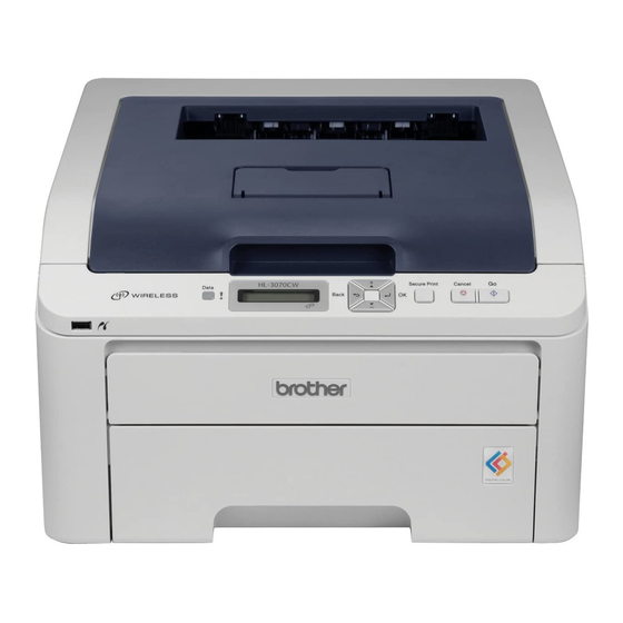
COMPONENTS Top cover sub ASSY Top cover arm R LED head control LED ASSY PCB ASSY Top cover arm L Paper eject guide ASSY Fuser cover Fuser unit Back cover Side cover R ASSY LVPS unit Main fan ASSY Registration sensor holder ASSY LV fan ASSY Toner LED... -
Page 13: Specifications List
SPECIFICATIONS LIST General Model HL-3040CN HL-3070CW Print method Electrophotographic LED color printer ® ® ® Resolution 2,400 dpi Windows Server 2008, Windows Vista , Windows Server ® (600 (main 2003 x64 Edition, Windows XP Professional x64 Edition, ® ® scanning) x... - Page 14 Model HL-3040CN HL-3070CW Power Printing Average 480 W at 25 °C (77 °F) consumption Ready Average 70 W at 25 °C (77 °F) Sleep Average 8 W at 25 °C (77 °F) Average 10 W at 25 °C (77 °F)
-
Page 15: Direct Print Feature
HL-3070CW Direct Print PDF version1.7 , JPEG, Exif+JPEG, PRN (created by HL-3040CN or HL- 3070CW printer driver), TIFF (scanned by all Brother MFC or DCP ® models), PostScript 3™ (created by HL-3070CW BRScript3 printer driver), XPS version 1.0 The data including JBIG2 image files, JPEG2000 image files and transparency files are not supported. - Page 16 <System requirements> Available Recom- Computer Platform & Operating Minimum Hard Processor Speed mended System Version Disk Space ® ® ® ® Intel Pentium 4 or 512 MB 2 GB 50 MB Windows Windows Server equivalent 2008 ® 64-bit (Intel 64 or ®...
-
Page 17: Network Connectivity
2000 Professional ® Mac OS X 10.3.9 or greater If you want to use the IPv6 protocol, visit http://solutions.brother.com/ for more information. BRAdmin Professional and Web BRAdmin are available as a download from http://solutions.brother.com/ Specifications are subject to change without notice. - Page 18 , Windows Server 2003, Windows XP and ® Windows 2000 TCP/IP printing ® Mac OS X 10.3.9 or greater printing If you want to use the IPv6 protocol, visit http://solutions.brother.com/ for more information. Specifications are subject to change without notice. Confidential...
- Page 19 XP Professional x64 Edition, Windows Server ® 2003, Windows XP Home Edition/Professional ® Edition, Windows 2000 Professional ® Mac OS X 10.3.9 or greater BRAdmin Professional and Web BRAdmin are available as a download from http://solutions.brother.com/ Specifications are subject to change without notice. Confidential...
-
Page 20: Service Information
Service Information These are key service information to maintain the product. - Machine life: approximately 100,000 pages or 5 years - MTBF (Meantime between failure): 4,000 hours - MTTR (Meantime to repair): 30 minutes - Maximum monthly volume: 25,000 pages - Periodical maintenance parts: Part Approximate life (page) -
Page 21: Consumables
Consumables Model HL-3040CN HL-3070CW Toner Life expectancy: cartridge Black Standard : Approximately 2,200 pages/cartridge Black Starter : Approximately 1,000 pages/cartridge Cyan, Magenta, Yellow Standard : Approximately 1,400 pages/cartridge Cyan, Magenta, Yellow Starter : Approximately 1,000 pages/cartridge * When printing A4/Letter-size paper in accordance with ISO/IEC 19798. -
Page 22: Paper
Paper 2.5.1 Paper handling Model HL-3040CN HL-3070CW Paper tray 250 sheets Paper Input Manual feed slot 1 sheet Option Paper Output Face-down 100 sheets Face-up 1 sheet (Straight paper path) Duplex Manual duplex Automatic duplex N/A Calculated with 80 g/m... -
Page 23: Type And Size Of Paper
2.5.3 Type and size of paper The printer loads paper from the installed paper tray or the manual feed slot. The names for the paper trays in the printer driver as follows: The name for the paper trays in the printer driver The name for the paper trays Paper tray Tray1... -
Page 24: Printable Area
Printable Area ■ PCL5C emulation When using PCL5C emulation, the edges of the paper that cannot be printed on are shown below. Portrait Physical page Printable area Logical page Physical page length Maximum logical page length Distance from edge of physical page to edge of logical page Note: Therefore, the machine can only print within the shaded area when you use a PCL driver. - Page 25 The table below shows the printable areas when printing on Portrait for each paper size. Size (mm) 215.9 279.4 203.2 279.4 6.35 4.23 Letter (inch) 0.25 0.17 (dots) 2,550 3,300 2,400 3,300 (mm) 215.9 355.6 203.2 355.6 6.35 4.23 Legal (inch) 0.25 0.17...
- Page 26 Landscape Physical page Printable area Logical page Physical page length Maximum logical page length Distance from edge of physical page to edge of logical page Note: - “Logical page” shows the printable area for a PCL driver. - Therefore, the machine can only print within the shaded area when you use a PCL driver. Specifications are subject to change without notice.
- Page 27 The table below shows the printable areas when printing on Landscape for each paper size. Size (mm) 279.4 215.9 269.2 215.9 5.08 4.23 Letter (inch) 10.6 0.17 (dots) 3,300 2,550 3,180 2,550 (mm) 355.6 215.9 345.4 215.9 5.08 4.23 Legal (inch) 13.6 0.17...
- Page 28 ■ PS3/PCL6 (PCLXL) emulation When using PS3/PCL6 (PCLXL) emulation, the edges of the paper that cannot be printed on are shown below. Portrait Physical page Printable area Physical page length Maximum logical page length Note: This is equivalent to the printable area for a PS driver. Specifications are subject to change without notice.
- Page 29 The table below shows the printable areas when printing on Portrait for each paper size. Size (mm) 215.9 279.4 207.4 270.9 4.23 4.23 Letter (inch) 8.17 10.67 0.17 0.17 (dots) 2,550 3,300 2,450 3,200 (mm) 215.9 355.6 207.4 347.1 4.23 4.23 Legal (inch)
- Page 30 Landscape Physical page Printable area Physical page length Maximum logical page length Note: This is equivalent to the printable area for a PS driver. Specifications are subject to change without notice. 1-19 Confidential...
- Page 31 The table below shows the printable areas when printing on Landscape for each paper size. Size (mm) 279.4 215.9 270.9 207.4 4.23 4.23 Letter (inch) 10.67 8.17 0.17 0.17 (dots) 3,300 2,550 3,200 2,450 (mm) 355.6 215.9 347.1 207.4 4.23 4.23 Legal (inch)
-
Page 32: Print Speeds With Various Settings
Print Speeds with Various Settings Print speed is up to 16 ppm for A4 size and 17 ppm for Letter size when loading A4 or Letter size paper from the paper tray in the plain paper mode. Actual print speed varies depending on the media type or paper size as shown in the tables below: <A4/Letter size>... -
Page 33: Theory Of Operation
CHAPTER 2 THEORY OF OPERATION Confidential... - Page 34 CHAPTER 2 THEORY OF OPERATION This chapter gives an overview of the printing mechanisms as well as the sensors, actuators and control electronics. It aids in understanding the basic principles of operation as well as locating defects for troubleshooting. CONTENTS 1.
-
Page 35: General Block Diagram
GENERAL BLOCK DIAGRAM Video control system Interface USB device or Extended RAM (USB Direct) Digital camera DIMM 144pin (HL-3070CW only) Interface Internal RAM (Wired LAN) Interface (Wireless LAN module) (HL-3070CW only) Video control block Interface (USB) Operation block (Panel) Engine control system Exposure system Engine control LED unit... -
Page 36: Electronics General Block Diagram
ELECTRONICS GENERAL BLOCK DIAGRAM Develop drive motor Toner/New sensor PCB Paper feed motor Drum motor origin sensor PCB Belt drive motor Internal temperature thermistor Develop release motor Engine PCB Fuser/eject drive motor Drum drive motor Registration solenoid Pick-up solenoid Density sensor shutter solenoid LV fan High-voltage HVPS... -
Page 37: Mechanics
MECHANICS Cross-section Drawing Exposure drum (M) Exposure drum (Y) Exit roller 2 Exposure drum (K) <Front> <Back side> Exposure drum (C) Pinch roller Cleaner sponge Develop roller Paper eject guide Supply roller Back cover Registration rear actuator Paper eject rear actuator Exit roller 1 PF registration roller Fuser cover... -
Page 38: Paper Feeding
Paper Feeding Paper eject function (Refer to “3.2.4”) <Front> <Back side> Manual feed slot path Manual feed function (Refer to “3.2.5”) Paper pick-up function (Refer to “3.2.2”) Plate-up function Paper tray path (Refer to “3.2.1”) Fig. 2-4 Confidential... -
Page 39: Plate-Up Function Of The Paper Tray
3.2.1 Plate-up function of the paper tray The plate of the paper tray is pushed up by the force exerted by the motor not by springs so as to keep pressure to the paper pick-up roller and enhance paper-feeding performance irrespective of the quantity of papers remaining in the tray. -
Page 40: Paper Supply
3.2.2 Paper supply When the paper pick-up solenoid is turned ON, the power of the paper feed motor rotates the paper pick-up roller, and it picks up a few sheets or one sheet of paper from the top of the sheets in the paper tray every time it is rotated and feeds it to the separation roller. -
Page 41: Paper Registration
3.2.3 Paper registration Passing of each sheet of paper which is separated by the separation roller is detected by the registration front actuator. Then, the paper is fed further for a certain time, and its front edge hits the stopped PF registration roller so that the paper skew is corrected. After such correction, the registration solenoid is turned OFF, the power of the paper feed motor rotates the PF registration roller, and the paper is fed to the belt unit. -
Page 42: Paper Eject
3.2.4 Paper eject Drive of the fuser/eject drive motor rotates the heat roller and pressure roller of the fuser unit, and toner on paper is fused as the paper is being fed. Paper moves along the paper eject guide and is ejected into the output tray from the exit roller 2 with its print side down. Exit roller 2 Paper eject guide Paper eject rear actuator... -
Page 43: Paper Supply From Manual Feed Slot And Paper Eject From Back
3.2.5 Paper supply from manual feed slot and paper eject from back When making print from the manual feed slot, set papers on it with the print side up. A sheet of paper which is inserted from the manual feed slot one by one presses the manual paper actuator, and consequently the actuator detects that there is a sheet of paper. -
Page 44: Toner Cartridge
Toner Cartridge 3.3.1 Type of toner cartridge This product has four types of toner cartridges, K (black), Y (yellow), M (magenta), and C (cyan), and each toner cartridge has starter toner cartridge and standard toner cartridge. The toner cartridges supplied with the product are starter toner cartridges, and the toner cartridges which are sold as consumable parts are standard toner cartridges. -
Page 45: Method Of Detecting Toner Life
3.3.3 Method of detecting toner life This product detects the life of the toner cartridges using the following two means. ■ Detection by the toner sensor This product has a function to detect the remaining toner by checking the level at which toner in a cartridge interrupts light using a transmissive light sensor. - Page 46 <Life of toner cartridge> The life of the toner cartridge varies according to the average number of print pages per job. (See the table below.) The number of printable pages is larger when making continuous prints in one job because deterioration of the develop roller is low. Relationship between average print page per 1 job and life of toner cartridges Average print page (page/job) Cartridge life (Standard-K)
-
Page 47: New Toner Detection
3.3.5 New toner detection When a toner cartridge is replaced and a new toner cartridge is mounted, there is a need to reset the develop bias voltage value (refer to next page) to the initial value and to reset prohibition of the print operation by clearing the display of "Toner Low" or "Replace Toner." The old and new toner cartridges can be identified using the new toner detection mechanism shown below. - Page 48 ■ Developing bias voltage Toner in use tends to have a low print density at the beginning of its use, but the density gradually becomes higher after a certain period of use if the bias voltage is kept at a certain level during development.
-
Page 49: Method Of Counting The Number Of Toner Replacements
3.3.6 Method of counting the number of toner replacements This machine keeps the number of times that the toner cartridges are replaced and the page counters to learn the usage of the machine. These counters will not be deleted even if the power is turned OFF. -
Page 50: Principle Of Color Overlapping
Principle of Color Overlapping The human eye distinguishes one color from others by receiving light’s three primary colors (Red, Green, Blue). When monochrome lights are received, each color can be sensed. However, when two-color lights, red (R) and green (G), are received, they are recognized as “yellow”;... -
Page 51: Basic Printing Principle
Basic Printing Principle The printing process consists broadly of 6 processes: Charging, Exposure, Development, Transfer, Fusing and Cleaning. <Printing process> (1) Charging: The surface of the drum is electrically charged (Primary Charge). (2) Exposure: A printed image is formed on the surface of the drum by applying LED beam (Electrostatic Latent Image). -
Page 52: Charging
3.5.1 Charging The exposure drum needs to be evenly electrified to coat toner beautifully on the exposure drum. Ions are produced by supplying high-voltage power to the corona wire. The flow of the ion charge is controlled by the constant voltage of the grid approximately 700 V and electrified the exposure drum surface evenly. -
Page 53: Exposure
3.5.2 Exposure Exposure is conducted by LED (Light Emitting Diode) arrays. Four LED arrays for K, Y, M and C are mounted as an LED ASSY on the top cover unit of the main unit. These four LED arrays do not emit different colors corresponding to toner colors, and they are the same parts in terms of structure. -
Page 54: Development
3.5.3 Development Toner is attracted to the latent-image area on the exposure drum where surface potential is lowered due to exposure. By controlling the developing bias voltage supplied to the develop roller, the amount of toner taken to the exposure drum is adjusted to keep printing density constant. 400 V (Changes depending on use condition) LED beam... -
Page 55: Transfer
3.5.4 Transfer By applying a minus charge to the transfer roller of the belt unit, the toner adhered to the exposure drum is transferred to paper which is traveling on the feed belt. Exposure drum (K) Exposure drum (Y) Exposure drum (M) Exposure drum (C) Belt unit Feed belt... -
Page 56: Fusing
3.5.5 Fusing The toner transferred on to the paper passes between the heat roller and the pressure roller in the fuser unit and are fused by heat and pressure. The main CPU detects surface temperature of the heat roller using the thermistor and turns ON/OFF the halogen heater lamp to keep the temperature constant. -
Page 57: Toner Cleaning
3.5.6 Toner cleaning <Flow of toner cleaning> (1) Toner remaining on the exposure drum which has not completely been transferred on to the paper is pulled onto the drum cleaner with a lower potential and the drum is cleaned. (2) After the above step, the potential of the drum cleaner is raised during printing, and such attracted toner is returned to the exposure drum again. -
Page 58: Location Of Sensors
Location of Sensors Name of sensor Type Position Function Paper eject rear Photosensor On the eject rear sensor The paper eject rear sensor PCB ASSY in the paper actuator detects that eject guide ASSY the paper passes through the fuser unit to check that no paper jam occurs between the heat roller and exit... - Page 59 Name of sensor Type Position Function Belt thermistor Thermistor Registration sensor Detects temperature holder ASSY in the product (at the center). Drum motor origin Photosensor On the drum motor Detects the phase of sensor origin sensor PCB ASSY the drum motor. in the side frame L Fuser/eject drive Photosensor...
- Page 60 ■ Location of sensors Belt thermistor Registration sensor holder ASSY Registration mark sensor L Density sensor Registration mark sensor R Eject gear cover Waste toner sensor holder Registration rear sensor Fuser/eject drive motor sensor Registration front sensor Registration front/rear sensor PCB ASSY Manual sensor Paper feed unit Waste toner sensor...
- Page 61 Fuser center thermistor Fuser side thermistor Fuser unit <Front> Fig. 2-27 2-27 Confidential...
-
Page 62: Adjustment Of Color Registration
Adjustment of Color Registration In this device, the drum and develop unit are prepared for K, Y, M, and C respectively. Four color images are combined into one image, and therefore color registration error might occur. Auto color registration error correction control is to calculate the color registration error amount and adjust the exposure timing as a means to prevent color registration error. - Page 63 CHAPTER 3 ERROR INDICATION AND TROUBLESHOOTING Confidential...
- Page 64 CHAPTER 3 ERROR INDICATION AND TROUBLESHOOTING This chapter details error messages and codes which the incorporated self-diagnostic function of the machine will display if any error or malfunction occurs. If any error message appears, refer to this chapter to find which parts should be checked or replaced. The latter half of this chapter provides sample problems which could occur in the main sections of the machine and related troubleshooting procedures.
-
Page 65: Introduction
INTRODUCTION Troubleshooting is the countermeasure procedures that the service personnel should follow if an error or malfunction occurs with the machine. It is impossible to anticipate all of the possible troubles which may occur in future and determine the troubleshooting procedures, so this chapter covers some sample troubles. -
Page 66: Components
Components Top cover sub ASSY Top cover arm R LED head control LED ASSY PCB ASSY Top cover arm L Paper eject guide ASSY Fuser cover Fuser unit Back cover Side cover R ASSY LVPS unit Main fan ASSY Registration sensor holder ASSY LV fan ASSY Toner LED... -
Page 67: Initial Check
Initial Check Check the following items before attempting to repair the machine. ■ Operating environment (1) Put your machine on a flat, stable surface such as a desk that is free of vibration and shocks. (2) Use the machine in a well-ventilated room; use the machine within the following ranges of temperature and humidity: temperature between 10 °C and 32.5 °C (50 °F to 90.5 °F), and the relative humidity is maintained between 20 % and 80 %. - Page 68 ■ Others (1) Condensation When the machine is moved from a cold place into a warm room, condensation may occur inside the machine, causing various problems as listed below. - Condensation on the optical surfaces such as the LED array may cause the print image to be light.
-
Page 69: Error Indications
ERROR INDICATIONS This machine includes a self-diagnosis function. If the machine does not work normally it judges that an error has occurred, and indicates the corresponding error message on the LCD, which in turn helps the service men to quickly find out the problem. Error Codes Error Refer... - Page 70 Error Refer Error Refer Problem Problem codes codes Waste toner box near full 3-27 Paper jam at the back of the machine 3-35 inside Toner life end (C) 3-28 Toner life end (M) 3-28 Toner of the color which is being 3-30 used reaches the end of life when Toner life end (Y)
- Page 71 Error Refer Error Refer Problem Problem codes codes RAM area for secure data full 3-42 Low-voltage power supply PCB failure 3-47 DIMM error 3-43 Waste toner box near full 3-48 Excess current to USB device 3-43 Waste toner box life end 3-48 No belt unit 3-44...
-
Page 72: Error Messages
Error Messages The error messages displayed on the LCD of the product and their description and measure are shown in the table below. Error message Description/ Measure Refer to: Access Error The USB device was removed while data was 3-43 (HL-3070CW only) processing. - Page 73 Error message Type of error Refer to: No Waste Toner Install the waste toner box. 3-44 Out of Memory If the LCD shows this error message when you print the 3-42 secure data, press Cancel button and delete the previously stored data. Except in the case of printing secure data and add more memory.
-
Page 74: Error Cause And Remedy
Error Cause and Remedy Check the User Check items first. If an error cannot be resolved, follow the procedures in numerical order in the Step field. ■ Error code 13 An error, which cannot be recorded, occurs while correction of developing bias is performed. <... - Page 75 ■ Error code 15 Correction of developing bias fails. < > User Check - Replace the belt unit with a new one. Step Cause Remedy Registration mark L PCB ASSY Replace the registration sensor holder failure ASSY. HVPS control PCB failure Replace the HVPS control PCB ASSY.
- Page 76 ■ Error code 18 Auto color registration fails. < > User Check - Replace the belt unit with a new one. - Replace the waste toner box with a new one. Step Cause Remedy Registration mark L PCB ASSY Replace the registration sensor holder failure ASSY.
- Page 77 ■ Error code 1B Drum Error Replace the Drum Unit. Cyan (C). Refer to the User's Guide. Error code 1C Drum Error Replace the Drum Unit. Magenta (M). Refer to the User's Guide. Error code 1D Drum Error Replace the Drum Unit. Yellow (Y). Refer to the User's Guide. Error code 83 Drum Error Replace the Drum Unit.
- Page 78 ■ Error code 20 (K), 21 (Y), 22 (M), 23 (C) Print Unable 20 Turn the power off and then back on again. Print Unable 21 Turn the power off and then back on again. Print Unable 22 Turn the power off and then back on again. Print Unable 23 Turn the power off and then back on again.
-
Page 79: Error Code 25
■ Error code 25 Print Unable 25 Turn the power off and then back on again. Develop drive motor error (Incorrect synchronized signal of the develop drive motor) Error code 26 Print Unable 26 Turn the power off and then back on again. Belt drive motor error Error code 28 Print Unable 28... - Page 80 ■ Error code 2C (K), 2D (Y), 2E (M), 2F (C) Print Unable 2C Turn the power off and then back on again. Print Unable 2D Turn the power off and then back on again. Print Unable 2E Turn the power off and then back on again. Print Unable 2F Turn the power off and then back on again.
- Page 81 ■ Error code 31 Print Unable 31 Turn the power off and then back on again. Density sensor error (Incorrect measurement value of the density sensor) Error code 32 Print Unable 32 Turn the power off and then back on again. Density sensor shutter performance malfunction <...
- Page 82 ■ Error code 33 Print Unable 33 Turn the power off and then back on again. Right color registration sensor error (Incorrect reading value of the color registration sensor (Right)) Error code 34 Print Unable 34 Turn the power off and then back on again. Left color registration sensor error (Incorrect reading value of the color registration sensor (Left)) <...
- Page 83 ■ Error code 36 Print Unable 36 Turn the power off and then back on again. Error occurs while the high-voltage power supply PCB is in ready state. Error code 40 Print Unable 40 Turn the power off and then back on again. Error occurs while the high-voltage power supply PCB is in operation * After the error code 36 is displayed for 5 seconds, the power of the main unit is forcibly turned off, and it takes 10 minutes to recover.
- Page 84 ■ Error code 38 Print Unable 38 Turn the power off and then back on again. External temperature sensor error Error code 39 Print Unable 39 Turn the power off and then back on again. External humidity sensor error Step Cause Remedy HVPS control PCB failure...
- Page 85 ■ Error code 3B Print Unable 3B Turn the power off and then back on again. Main PCB RAM error (DIMM access error) Error code 3E Print Unable 3E Turn the power off and then back on again. NVRAM transfer error Error code E6 Print Unable E6 Turn the power off and then back on again.
- Page 86 ■ Error code 43 Print Unable 43 Turn the power off and then back on again. Main/Engine ASIC transfer error Step Cause Remedy Harness connection failure Check the harness connection between between the main PCB ASSY the main PCB ASSY and engine PCB and engine PCB ASSY ASSY, and reconnect it.
- Page 87 ■ Error code 48 (K), 49 (Y), 4A (M), 4B (C) Replace Drum (K) Replace Drum (Y) Replace Drum (M) Replace Drum (C) Drum unit is at the end of life. (The drum counter value reaches the end of life.) * When all four colors reach the end of life at the same time.
- Page 88 ■ Error code 54 Replace Fuser Fuse unit is at the end of life. (The counter value of the fuser unit reaches the end of life.) Step Cause Remedy Fuser unit is at the end of life. Replace the fuser unit. ■...
- Page 89 ■ Error code 58 Fuser Error Turn the power off, then on again. Leave the machine for 15 min. Fuser unit error (Some kind of temperature error of the fuser unit occurs.) Error code 59 Self-Diagnostic Will Automatically Restart within 15 minutes. Fuser unit error (Re-detection of fuser unit failure upon startup after the error code 58 occurs.) * If the same error is detected again 15 minutes later, the message below is indicated.
- Page 90 Error code 78 Print Unable 78 Turn the power off and then back on again. Fuser unit error (The center thermistor detects rapid temperature falling.) Step Cause Remedy Harness connection failure Check the harness connection between between fuser unit connector and the fuser unit connector and eject front eject front sensor PCB ASSY sensor PCB ASSY, and reconnect it.
- Page 91 ■ Error code 5E Replace Belt The belt unit is at the end of life. (The belt unit counter value reaches the end of life.) < > User Check - Replace the belt unit with a new one. - After replacing the belt unit, reset the counter using the control panel cover ASSY on the machine. (Refer to “2.3 Parts Life Reset Function”...
- Page 92 ■ Error code 60 (C), 61 (M), 62 (Y), 63 (K) Replace Toner Open the Top Cover, replace Toner Cartridge. Cyan (C). Replace Toner Open the Top Cover, replace Toner Cartridge. Magenta (M). Replace Toner Open the Top Cover, replace Toner Cartridge. Yellow (Y). Replace Toner Open the Top Cover, replace Toner Cartridge.
- Page 93 ■ Error code 64 (C), 65 (M), 66 (Y), 67 (K) Toner Low (#) * Any of K, Y, M, or C, which refer to colors, is indicated in #. Toner cartridge will reach the end of life soon. (The counter value of the develop roller reaches 90 % of life, or the toner sensor detects toner near empty.) <User Check>...
- Page 94 ■ Error code 73 Print Unable 73 Turn the power off and then back on again. Recording ASIC read/write error Step Cause Remedy Harness connection failure of Check the harness connection between LED head control PCB ASSY the main PCB ASSY and LED head control PCB ASSY, and reconnect them.
- Page 95 ■ Error code 75 Cooling Down Wait for a while Cooling down the inside of the machine to protect it. The machine indicates “Cooling Down” in one of the conditions below. - The temperature inside the machine is high. - Both ends of the heat roller are heated extraordinarily. - The paper media is replaced.
- Page 96 ■ Electrodes location of the drum unit and toner cartridge * Black only Fig. 3-3 ■ Electrodes location of the belt unit Fig. 3-4 3-32 Confidential...
- Page 97 ■ Electrodes location of waste toner box Fig. 3-5 ■ Electrodes location of main body Fig. 3-6 < > How to clean the electrodes Turn off the power switch. Unplug the machine from the AC power outlet, and leave the machine for a few minutes.
- Page 98 ■ Error code 81 Calibrate Calibration failed. See Troubleshooting chapter in User’s Guide. Incorrect density sensor measurement value when implementing adjustment of color density from the control panel cover ASSY. Error code 82 Calibrate Calibration failed. Press Go, and try again. Density patch measurement is not completed normally when implementing adjustment of color density from the control panel cover ASSY.
- Page 99 ■ Error code 84 Jam Rear Open the Back Cover and remove the jammed paper, then press Go. Paper jam at the back of the machine inside (The eject front sensor sticks at ON after the registration rear actuator is turned OFF.) Error code 88 Jam Inside Open the Top Cover, pull out all 4 Drum Units completely and remove the...
- Page 100 ■ Error code 8A Jam Tray 1 Remove the jammed paper from Tray 1, then press Go. Paper jam in the paper tray (The registration front sensor sticks at ON.) < > User Check - Check if the paper is jammed in the paper tray. If jammed, remove it. - Adjust the paper guide corresponding to the paper size.
- Page 101 ■ Error code 8E Registration Registration failed. Press Go, and try again. Error in the adjustment of color registration result when implementing it from the control panel cover ASSY. Error code 8F Registration Registration failed. See Troubleshooting chapter in User’s Guide. Detection of abnormal value of registration sensor sensitivity when implementing adjustment of color registration from the control panel cover ASSY.
- Page 102 ■ Error code 94 No Paper Load <size> paper, then press Go. - No paper in paper tray (The registration front actuator is not turned ON after a certain period of time has passed.) - Paper tray is not installed into the machine. <...
- Page 103 ■ Error code 96 No Paper Load <size> paper in Tray. No paper in all trays (The manual paper actuator is not ON, and the registration front actuator is not turned ON after a certain period of time has passed.) <...
- Page 104 ■ Error code 9F No Paper Reload paper, then press Go. No paper while printing < > User Check - Load the paper into the paper tray. ■ Error code A1 Cover is Open Close the Top Cover. Top cover opened (The top cover open switch sticks at OFF.) <...
- Page 105 ■ Error code C0 (K) Cartridge Error Put the Black (K) Toner Cartridge back in. Identification failure for a new toner cartridge (K) (The new toner sensor sticks at ON.) Error code C1 (Y) Cartridge Error Put the Yellow (Y) Toner Cartridge back in. Identification failure for a new toner cartridge (Y) (The new toner sensor sticks at ON.) Error code C2 (M) Cartridge Error...
- Page 106 ■ Error code C6 Toner Error One or more Toner Cartridges are not detected. Pull out and reinsert all 4 Toner Cartridges. Pressure engagement/disengagement failure of toner cartridge (Develop release sensor output error) Step Cause Remedy Harness connection failure of Check the harness connection of the develop release motor develop release motor and reconnect it.
- Page 107 ■ Error code C9 DIMM Error Make sure that the DIMM is inserted correctly. DIMM error < > User Check - Check if the DIMM is installed correctly. - Replace the DIMM with a new one. ■ Error code CA Unusable Device Remove the Device.
- Page 108 ■ Error code CB No Belt Unit Open the Top Cover, pull out all 4 Drum Units completely and install the Belt Unit. Belt unit is not installed into the machine. (The density sensor detects that the belt unit is not installed.) <...
- Page 109 ■ Error code CF Replace WT Box Replace the Waste Toner Box. Refer to the User’s Guide for instructions. Waste toner box full (500 pages are printed after the waste toner sensor sticks at ON.) Note: The same message appears in the case of the error code F4. <...
- Page 110 ■ Error code E1 Print Unable E1 Turn off and on. Program error < > User Check - Turn the power off and on. Step Cause Remedy Main PCB failure Replace the main PCB ASSY. ■ Error code E2 Print Unable E2 Turn the power off and then back on again.
- Page 111 ■ Error code E9 Print Unable E9 Turn the power off and then back on again. Maintenance monitor error (The engine software detects an incorrect setting value.) Step Cause Remedy Harness connection failure of Check the harness connection between engine PCB ASSY the main PCB ASSY and engine PCB ASSY, and reconnect it.
- Page 112 ■ Error code F2 WT Box End Soon The waste toner box near full. (Cleaning high voltage discharge due to reaching the life of the cleaning roller) Note: The same message appears in the case of the error code 5F. <...
- Page 113 ■ Error code FA (K), FB (C), FC (M), FD (Y) No Toner Open the Top Cover, then install Toner Cartridge. Black (K) No Toner Open the Top Cover, then install Toner Cartridge. Cyan (C) No Toner Open the Top Cover, then install Toner Cartridge. Magenta (M) No Toner Open the Top Cover, then install Toner Cartridge.
- Page 114 ■ Error code FE Detection of incorrect measurement value of density sensor sensitivity calibration < > User Check - Check if the 4-color drum units are properly installed in the product. Step Cause Remedy Belt unit failure Replace the belt unit. Harness connection failure of Check the harness connection of the registration mark L PCB ASSY...
-
Page 115: Paper Feeding Problems
PAPER FEEDING PROBLEMS Problems related to paper feeding are end user recoverable if following the User Check items. If the same problem occurs again, follow each procedure in the order of the number described in the Step column in the tables below. No Feeding <... -
Page 116: Double Feeding
Double Feeding < > User Check - Check if the paper is loaded into the paper tray correctly. - Turn over the stack of paper in the paper tray, or try rotating the paper 180° in the paper tray. - Check if the thickness of the paper is 75 to 105g/m - Set out papers and reload them into the paper tray. - Page 117 ■ Paper jam in the back cover and paper eject section Step Cause Check Result Remedy Foreign object Is there a foreign object Remove the foreign around fuser unit around the fuser unit? object. Paper eject rear Does the paper eject Replace the paper eject actuator top failure rear actuator top move...
-
Page 118: Dirt On Paper
Dirt on Paper < > User Check - Check if the paper is loaded into the paper tray correctly. - Turn over the stack of paper in the paper tray, or try rotating the paper 180° in the paper tray. - Replace the waste toner box with a new one. -
Page 119: Curl Of Paper
Curl of Paper < > User Check - Change the curl improvement mode setting of the driver. - Switch the delivery roller switch lever. Note: Be sure not set the curl improvement mode of the driver and switch to the delivery roller switch lever at the same time because it might worsen the level of curl. -
Page 120: Image Defect Troubleshooting
IMAGE DEFECT TROUBLESHOOTING Image Defect Examples Light on the whole page One color is light Dark Faulty registration All one color Poor fixing Completely blank Image distortion Dirt on the back of paper Vertical streaks Vertical streaks in a light background Vertical streaks in a dark background Horizontal stripes White vertical streaks on one color image... -
Page 121: Pitch Indicated In Roller Image
Pitch Indicated in Roller Image Image defects which occur periodically may be caused by a failure of the roller. By referring to the table below, specify the cause based on the pitch indicated in the image of each roller. Parts name The pitch which appears in the image Develop roller 31 mm... -
Page 122: One Color Is Light
■ One color is light < > User Check - Open and close the top cover and make print again. - Check the machine’s environment. High temperature and high humidity or low temperature and low humidity conditions can cause this problem. - Replace the toner cartridge or drum unit with a new one. -
Page 123: Faulty Registration
Step Cause Check Remedy Result HVPS control PCB Is the problem solved Replace the HVPS failure after replacing the control PCB ASSY. HVPS control PCB ASSY? High-voltage power Is the problem solved Replace the supply PCB failure after replacing the high-voltage power high-voltage power supply PCB ASSY. - Page 124 ■ Dark < > User Check - Check the machine’s environment. High temperature and high humidity or low temperature and low humidity conditions can cause this problem. - Clean the corona wire. - Replace the toner cartridge or drum unit with a new one. - Adjust the color density from the control panel cover ASSY.
-
Page 125: Poor Fixing
■ Poor fixing < > User Check - Open and close the top cover and make print again. - Adjust the color density from the control panel cover ASSY. - Check the machine’s environment. High temperature and high humidity or low temperature and low humidity conditions can cause this problem. - Replace the belt unit with a new one. -
Page 126: Image Distortion
■ Completely blank < > User Check - Replace the belt unit with a new one. - Replace the toner cartridge or drum unit with a new one. Step Cause Check Remedy Result Developing bias Are the electrodes on the Clean both electrodes. -
Page 127: All One Color
■ All one color Memo: You can check this image defect with the function code 71. (Refer to “1.4.14 Color test pattern (Function code 71)” in Chapter Step Cause Check Remedy Result Corona wire Are the electrodes on Clean both electrodes. failure the drum unit of the (Refer to... - Page 128 ■ Dirt on the back of paper < > User Check - Replace the waste toner box with a new one. - Replace the belt unit with a new one. Step Cause Check Remedy Result Fuser unit dirty Is the pressure roller Print approximate 10 dirty? pages.
-
Page 129: Vertical Streaks
■ Vertical streaks < > User Check - This problem may occur with noise which is caused by dirt on the corona wire in the drum unit. In this case, clean the corona wire. - Replace the drum unit with a new one. - Replace the toner cartridge with a new one. - Page 130 ■ Vertical streaks in a light background < > User Check - Clean the inside of the machine and the corona wire in the drum unit. - Clean the LED array with a soft lint-free cloth. - Replace the toner cartridge with a new one. - Replace the drum unit with a new one.
-
Page 131: Horizontal Stripes
■ Horizontal stripes < > User Check - Clean the inside of the machine and the corona wire in the drum unit. - Replace the drum unit with a new one. Step Cause Check Remedy Result Dirt on the charged Are the electrodes on Clean both electrodes. - Page 132 ■ White vertical streaks on one color image < > User Check - Check if there is no dust in the gap between the toner cartridge and drum frame. - Clean the relevant color LED array on which color loss occurs with a soft lint-free cloth. - Replace the toner cartridge with a new one.
-
Page 133: Faint Print
■ White horizontal stripes on one color image < > User Check - The problem may disappear by itself. Try printing multiple pages to clear this problem especially if the machine has not been used for a long time. - Replace the toner cartridge with a new one. - The drum unit may be damaged. - Page 134 ■ White spots on one color image < > User Check - Toner may be empty. Replace the toner cartridge with a new one. - If the same problem occurs after printing a few pages, the adhesive of the label or the like, paper powder or dirt may be attached on the surface of the exposure drum.
- Page 135 Note: If there is any problem in the print quality, be sure to clean the drum unit in accordance with “Drum cleaning function of product” provided below. If the problem still persists, be sure to clean the drum unit manually in accordance with “Drum unit cleaning”...
- Page 136 Note: - Make sure that the paper is straight and in the correct position on the manual feed slot. If it is not, the paper may not be fed properly, resulting in a skewed printout or a paper jam. - Do not put more than one piece of paper in the manual feed slot at any one time, as it may cause a jam.
- Page 137 <Drum unit cleaning> (1) Pull the drum unit out of the machine and take all the toner cartridges out of the drum unit. Note: We recommend that you place the drum unit on a clean, flat surface with a piece of disposable paper underneath it in case you accidentally spill or scatter toner.
- Page 138 ■ One color spots or dirt < > User Check - Damp (wet) paper might be used. Try to changing to freshly unopened paper. - Toner may be empty. Replace the toner cartridge with a new one. - If the same problem occurs after printing a few pages, the adhesive of a label or the like, paper powder or dirt may be attached on the surface of the exposure drum.
-
Page 139: One Color Band
■ One color band < > User Check - Clean the inside of the machine and the corona wire in the drum unit. If the same problem occurs after cleaning, replace the drum unit with a new one. - The paper tray ground terminal provided in the machine body may be dirty. Clean the contact with a dry cloth. -
Page 140: Horizontal Lines
■ Horizontal lines < > User Check - The paper tray ground terminal provided in the machine body may be dirty. Clean the contact with a dry cloth. - Replace the drum unit with a new one. - Replace the toner cartridge with a new one. Step Cause Check... -
Page 141: Color Misregistration
■ Ghost <User Check> - Check the machine’s environment, conditions such as high humidity may cause this situation to occur. - Check that the appropriate media type is selected in the printer driver. - Replace the drum unit with a new one. Step Cause Check... - Page 142 ■ Fogging <User Check> - Replace the toner cartridge with a new one. - Replace the drum unit with a new one. - Do not use acid paper. Step Cause Check Remedy Result Toner/new Is the toner sensor Replace the toner/new sensor PCB failure performed normally by sensor PCB ASSY.
- Page 143 ■ Unstable color density <User Check> - Make a print on a different type of paper. - Replace the belt unit with a new one. - Replace the drum unit with a new one. - Replace the waste toner box with a new one. - Replace the toner cartridge with a new one.
-
Page 144: Hollow Print
■ Hollow print <User Check> - Select “Improve Toner Fixing” in the printer driver, or select “Thicker Paper” in Paper Type. - Check the machine’s environment, conditions such as high humidity and low humidity may cause this situation to occur. - Make a print on a different type of paper. -
Page 145: Software Setting Problems
For Macintosh, has the Verify the product ID. connection product ID been (Hexadecimal) verified? Product ID: HL-3040CN: 0037 HL-3070CW: 0038 USB direct interface Is the problem solved Replace the USB direct relay PCB failure after replacing the USB interface relay PCB... -
Page 146: Network Problems
NETWORK PROBLEMS Cannot Make a Print through Network Connection < > User Check - Check the descriptions in the network user’s guide. - Restore the settings at factory shipment. (Refer to User's guide) Step Cause Check Remedy Result Mismatch of MAC Is the problem solved Obtain the MAC address (Ethernet... -
Page 147: Others Problems
OTHERS PROBLEMS The Machine is Not Turned ON, or The LCD Indication Does Not Appear. Step Cause Check Remedy Result Harness Is the harness of the Reconnect the panel connection failure panel PCB ASSY PCB ASSY harness. of panel PCB connected correctly? ASSY Harness... -
Page 148: The Fan Does Not Work
The Fan Does Not Work. Step Cause Check Remedy Result Harness Is the harness of the Reconnect the harness connection failure appropriate fan of the appropriate fan of the appropriate connected correctly? correctly. Failure of the Is the problem solved Replace the appropriate appropriate fan after replacing the... -
Page 149: Periodical Maintenance
CHAPTER 4 PERIODICAL MAINTENANCE Confidential... - Page 150 CHAPTER 4 PERIODICAL MAINTENANCE This chapter details consumable parts and periodical maintenance parts. This chapter also covers procedures for disassembling and assembling periodical maintenance parts. CONTENTS 1. SAFETY PRECAUTIONS ................4-1 2. CONSUMABLE PARTS ................4-1 3. PERIODICAL MAINTENANCE PARTS .............4-2 3.1 Periodical Maintenance Parts ..................4-2 3.2 Procedures to Replace Periodical Maintenance Parts ..........
-
Page 151: Safety Precautions
SAFETY PRECAUTIONS To avoid creating secondary problems by mishandling, follow the warnings below during maintenance work. WARNING - Always turn off the power switch and unplug the power cord from the power outlet before accessing any parts inside the machine. - When opening the top cover or back cover to access any parts inside the machine, never touch the shaded parts shown in the following figures. -
Page 152: Periodical Maintenance Parts
PERIODICAL MAINTENANCE PARTS Periodical Maintenance Parts Periodical maintenance parts are the parts to be replaced periodically to maintain product quality. These parts would affect the product quality if they loose their functionality even if they do not appear to be damaged or there is no change in their appearance. The periodical maintenance parts listed in the table below should be replaced according to the service life. -
Page 153: Procedures To Replace Periodical Maintenance Parts
Procedures to Replace Periodical Maintenance Parts ■ Preparation Prior to proceeding with the disassembly procedure, (1) Unplug - the AC cord, - the USB cable, if connected, - the LAN cable, if connected, and - the USB cable for PictBridge or USB flash memory drive, if connected. (2) Remove the Paper tray. -
Page 154: Fuser Unit
3.2.1 Fuser unit <Uninstalling procedure> (1) Open the Back cover. Back cover <Back side> Fig. 4-1 (2) Release the Hook and remove the Back cover stopper L and R from the Main body. Main body Hook Back cover stopper L Back cover Back cover stopper R <Back side>... - Page 155 (3) Remove the Bush of the Back cover from the Shaft at the right side of the Main body. Bush Main body Shaft <Right side> Shaft Back cover Bush <Back side> Fig. 4-3 (4) Remove the Back cover from the Shaft at the left of the Main body. Main body <Left side>...
- Page 156 (5) Release the Fuser cover lock lever L and R, and open the Fuser cover. Fuser cover lock lever L Fuser cover lock lever R Fuser cover lock lever L Fuser cover <Back side> Fuser cover lock lever R Fig. 4-5 (6) Take out the Shaft at the left side of the Fuser cover from the Notch on the Bush of the Side frame L.
- Page 157 (8) Remove the Taptite bind B M3x12 screw, and then remove the Fuser cover L from the Fuser unit. Fuser cover L Taptite bind B M3x12 Fuser unit <Back side> Fig. 4-7 (9) Remove the Taptite bind B M3x12 screw, and then remove the Fuser cover R from the Fuser unit.
- Page 158 (10) Disconnect the two Connectors (CN1, CN3) from the Eject front sensor PCB ASSY. Connector Eject front sensor PCB ASSY Connector <Back side> Fig. 4-9 (11) Disconnect the two Electrode terminals from the Fuser unit. Electrode terminal (small) Electrode terminal (large) Fuser unit <Back side>...
- Page 159 (12) Remove the two Taptite pan B M4x14 screws, and then remove the Fuser unit from the Main body while holding the “A.” Main body Taptite pan B M4x14 “A” Pressure roller ASSY Fuser unit Taptite pan B M4x14 <Back side> Fig.
-
Page 160: Installing Procedure
<Installing procedure> (1) Assemble the Fuser unit while holding the “A”, and then secure it with the two Taptite pan B M4x14 screws. Main body Taptite pan B M4x14 “A” Pressure roller ASSY Fuser unit Taptite pan B M4x14 <Back side> Fig. - Page 161 (2) Connect the two Electrode terminals into the Fuser unit. Electrode terminal (small) Electrode terminal (large) Fuser unit <Back side> Fig. 4-15 (3) Connect the two connectors (CN1, CN3) into the Eject front sensor PCB ASSY. Connector Eject front sensor PCB ASSY Connector <Back side>...
- Page 162 (4) Assemble the Fuser cover R to the Fuser unit with the Taptite bind B M3x12 screw. Note: Do not pinch the harness from the low-voltage power supply PCB ASSY to the Fuser unit. Fuser cover R Taptite bind B M3x12 Fuser unit <Back side>...
- Page 163 (6) Assemble the Shaft at the right side of the Fuser cover to the Bush of the LVPS cover. (7) Assemble the Shaft at the left side of the Fuser cover to the Notch on the bush of the Side frame L.
- Page 164 (9) Assemble the Back cover to the Shaft at the left side of the Main body. Main body <Left side> Shaft Back cover Fig. 4-21 (10) Assemble the Bush of the Back cover to the Shaft at the right side of the Main body. Bush Main body Shaft...
- Page 165 (11) Assemble the back cover stopper L and back cover stopper R to the main body. Main body Hook Back cover stopper L Back cover <Back side> Back cover stopper R Fig. 4-23 (12) Close the Back cover. Back cover <Back side>...
-
Page 166: Paper Feeding Kit
3.2.2 Paper feeding kit <Uninstalling procedure> (1) Release the two Hooks of the Separation pad ASSY from the Paper tray. (2) Release the two Pins to remove the Separation pad ASSY from Paper tray. Hook Separation pad ASSY Hook Paper tray Fig. - Page 167 (4) Push the Lift arm to the back and remove “B” of the Roller holder ASSY from “A” of the Lift arm, and the Roller holder ASSY rotates in the direction of the arrow 4b. “A” Roller holder ASSY “B” Paper feed unit Lift arm “B”...
- Page 168 <Installing procedure> (1) Align the shaft of the roller holder ASSY to the hole of the Paper feed unit and insert it into the hole. Paper feed unit Paper feed unit Roller holder ASSY Shaft Hole Fig. 4-29 (2) Slide the Roller holder ASSY in the direction of the arrow 2a and 2b in this order, and fit the “B”...
- Page 169 (3) Turn the Roller holder ASSY in the direction of the arrow 3a and insert the “D” of the Roller holder ASSY into the “C” of the Lift arm. “C” Roller holder ASSY “D” Paper feed unit Lift arm “D” Roller holder ASSY “C”...
- Page 170 (5) Put the two Pins of the Separation pad ASSY into the Paper tray. Note: Apply grease to the separation pad ASSY before mounting the Paper tray. (Refer to “4. LUBRICATUION” in Chapter Separation pad ASSY Paper tray Fig. 4-33 (6) Set the Pad spring in a way that the “E”...
-
Page 171: Disassembly And Assembly
CHAPTER 5 DISASSEMBLY AND ASSEMBLY Confidential... - Page 172 CHAPTER 5 DISASSEMBLY AND ASSEMBLY This chapter describes procedures for disassembling and assembling the machine with relates notes. The provided disassembly order flow enables you to take in the quickest way to get an involved part at a glance. At the start of disassembling, you can check the disassembly order flow which guides you through a shortcut to get to the part.
- Page 173 8.16 Panel Light Guide ....................5-57 8.17 Front Cover......................5-58 8.18 Manual Feed Slot ASSY ..................5-60 8.19 TC Arm Spring ......................5-61 8.20 Arm Guide L Cover ....................5-65 8.21 Top Cover Sub ASSY ..................... 5-66 8.22 Inner Chute 2 ASSY ....................5-69 8.23 FFC Harness:MAIN-LED CTL ................
- Page 174 8.54 Drum Motor Origin Sensor PCB ASSY..............5-128 8.55 LV Fan ASSY......................5-129 8.56 Main Fan ASSY ....................5-131 8.57 Low-voltage Power Supply PCB ASSY ..............5-132 8.58 Registration Sensor Holder ASSY ................ 5-137 8.59 High-voltage Power Supply PCB ASSY ............... 5-138 8.60 HVPS Control PCB ASSY ..................
-
Page 175: Safety Precautions
SAFETY PRECAUTIONS To avoid creating secondary problems by mishandling, follow the warnings and precautions below during maintenance work. WARNING Some parts inside the machine are extremely hot immediately after the machine is used. When opening the top cover or back cover to access any parts inside the machine, never touch the shaded parts shown in the following figures. -
Page 176: Packing
PACKING CD ASSY Accessory bag CD ASSY Quick Setup guide Option carton Option carton Drum/Toner ASSY AC cord Polystyrene pad upper Machine Polystyrene pad lower Carton Confidential... -
Page 177: Screw Torque List
SCREW TORQUE LIST Note: For verifying the shape of each screw, refer to “APPENDIX 4 SCREW CATALOGUE”. Tightening torque Location of screw Screw type Q'ty · · m (kgf Fuser cover L Taptite bind B M3x12 0.60±0.10 (6±1) Fuser cover R Taptite bind B M3x12 0.60±0.10 (6±1) Fuser unit... - Page 178 Tightening torque Location of screw Screw type Q'ty · · m (kgf Paper feed unit Taptite cup S M3x6 SR 0.80±0.10 (8±1) Shoulder screw 0.80±0.10 (8±1) PF upper cover ASSY Taptite cup B M3x10 0.60±0.10 (6±1) Registration front/rear sensor Taptite cup B M3x8 0.55±0.05 (5.5±0.5) PCB ASSY Front chute ASSY...
-
Page 179: Lubrication
LUBRICATION The kind of the lubricating oil Lubrication point Quantity of lubrication (Maker name) MOLYKOTE PG-661 (W) Belt drive gear 2 mm dia. ball (Dow Corning) LED ASSY 1 mm dia. ball FLOIL BG-MU (Kanto Kasei) Belt drive gear 2 mm dia. ball MOLYKOTE EM-D110 Separation pad ASSY 2 mm dia. - Page 180 Paper tray 2 places (one for each to the right and left) EM2: MOLYKOTE EM-D110 (2 mm dia. ball) 1 place LED ASSY PG1: MOLYKOTE PG-661 (W) (1 mm dia. ball) Confidential...
-
Page 181: Overview Of Gears
OVERVIEW OF GEARS When ordering spare parts, please refer to Parts reference list. ■ Develop drive <Development view> Drum develop drive unit Side frame L <Left side> <Layout view> Develop drive plate ASSY Drum develop drive unit <Name of gears> LU5128 Idle gear 100 LU5126... - Page 182 ■ Drum develop drive <Development view> Drum develop drive unit <Layout view> Drum develop drive unit <Name of gears> LU5139 Drum drive gear ASSY LU5136 Coupling idle gear 35 LU5132 Develop coupling gear LU6157 Drum drive gear 60 LU5136 Coupling idle gear 35 LU5132 Develop coupling gear LU6158...
- Page 183 ■ Cleaner PF <Development view> Side frame L <Left side> <Layout view> * Outside of side frame L <Name of gears> LU5108 Gear 70 LU5744 Registration differential gear LU5110 Idle gear 25 R LU5097 Gear 32/21 LU5110 Idle gear 25 R LU5100 Gear 26-51 LU5112...
- Page 184 ■ PF drive <Development view> Side frame L <Front> <Layout view> * Inside of side frame L <Name of gears> LR0910 Hook spring LU5089 Planetary clutch ASSY LU5093 LM hook B LR0910 Hook spring LU5094 LM hook C LU5105 Worm Z33 LU5095 P/P gear 26 sector LU5106...
-
Page 185: Harness Routing
HARNESS ROUTING Top Cover Unit Top cover sub ASSY Boss Hook Hook Top cover sub ASSY Hook Sub frame ASSY LED head control PCB ASSY Hook Front LED main FFC film Side frame L LED power relay PCB ASSY Hole Slit Front Front... - Page 186 Registration Front/Rear Sensor PCB ASSY Side frame R Registration front/rear Front sensor PCB ASSY Paper feed unit Hook Hole HVPS control PCB ASSY Manual Sensor PCB ASSY Side frame R Front Registration front/rear sensor PCB ASSY Hook Hole Slit Hook Hole Front chute ASSY Hook...
- Page 187 PF Registration Solenoid, Pick-up Solenoid Pick-up solenoid Cleaner PF gear cover PF registration solenoid Hook Front Side frame L Hook Hook Front Side frame L PF line holder Hook Hook Hook Engine PCB ASSY PF line holder Cleaner PF gear cover Hook 5-13 Confidential...
- Page 188 Belt Drive ASSY Engine insulation sheet Belt drive ASSY Hook Engine PCB ASSY Front Side frame L Hook Engine insulation sheet Develop Release Motor ASSY PF line holder Hook Side frame L Develop release motor ASSY Hook Front Hook Hook Engine PCB ASSY PF line holder 5-14...
- Page 189 Drum Motor Origin Sensor PCB ASSY Drum motor origin sensor PCB ASSY Hook Side frame L Engine insulation sheet Hook Engine PCB ASSY Engine insulation sheet Front Hole Fuser/Eject Drive Motor, Fuser/Eject Drive Motor Sensor PCB ASSY Fuser/eject drive motor Eject gear cover Engine insulation sheet sensor PCB ASSY...
- Page 190 Toner/New Sensor PCB ASSY Hook Toner/New sensor PCB ASSY Guide Line holder M Engine PCB ASSY Hook Hook Hook Hook Line holder M Line holder M Engine PCB ASSY Side frame L Front Paper Feed Motor ASSY, Drum Drive Motor Hook Drum drive motor PF line holder...
- Page 191 Control Panel Cover ASSY (HL-3070CW only) (USB Direct Interface Relay PCB ASSY) Core Hook Control panel cover ASSY Hook Side frame L Main PCB ASSY Control panel Hook cover ASSY Main shield cover plate ASSY A view Hook USB direct interface relay Front PCB ASSY...
- Page 192 Control Panel Cover ASSY (HL-3070CW only) (Wireless LAN PCB ASSY, Panel PCB ASSY) Hook Hook Control panel cover ASSY Wireless LAN PCB ASSY Panel PCB ASSY Hook Control panel cover ASSY Panel harness protective sheet Side frame L Control panel cover ASSY Hook Main PCB ASSY Hook...
- Page 193 Control Panel Cover ASSY (HL-3040CN only) (Panel PCB ASSY) <A view> Hook Side frame L Front Hook Main PCB ASSY Guide Hook Control panel Control pane cover ASSYl cover ASSY Guide Panel PCB ASSY Main PCB ASSY Hook Front Side frame L...
- Page 194 Eject Rear Sensor PCB ASSY Slit Slit Hook Hook Eject rear sensor PCB ASSY Eject rear sensor PCB ASSY Lower air duct Hook Side frame L Hole Paper eject guide Hole Main PCB ASSY Front Side frame R Front Eject Front Sensor PCB ASSY Side frame L Main PCB ASSY Front...
- Page 195 Waste Toner Sensor Hook Waste toner sensor holder Waste toner sensor Waste toner sensor Side frame R Side frame R Wire cover 2 Front Front Hole Side frame R HVPS control PCB ASSY Hook 5-21 Confidential...
-
Page 196: Toner Led Pcb Assy
Main Fan A SSY, LV Fan ASSY Front Side frame R Main fan ASSY Hook Hook Hook LV fan ASSY High-voltage power supply PCB ASSY Develop Release Sensor PCB ASSY, Top Cover Open Switch, Toner LED PCB ASSY Top cover open switch Toner LED PCB ASSY Hook Hook... - Page 197 ASSY Registration Sensor Holder Hole Front Side frame L Hook Registration sensor holder ASSY Hole Side frame L Hole Hook Registration mark relay PCB ASSY Front 5-23 Confidential...
-
Page 198: Back Cover Sensor
Low-voltage Power Supply PCB ASSY Hook Eject gear cover Front Side frame L Main PCB ASSY Front Side frame L Engine PCB Hook ASSY Hole Engine insulation LVPS cover sheet Hole Low-voltage power supply PCB ASSY Back Cover Sensor Side frame L A view <A view>... - Page 199 HVPS Control PCB ASSY Side frame R Hook A view Main PCB ASSY Hook Hook Hook Engine PCB ASSY Front Front cover top ASSY Side frame L <A view> Hook Main PCB ASSY Side frame L Side frame R Hook Hook HVPS control PCB ASSY...
-
Page 200: Disassembly Flow
DISASSEMBLY FLOW Disassembly/Re-Assembly (second) 8.19 20s/20s 8.20 10s/10s 15s/15s 30s/30s Side Cover L Arm Guide L Side Cover R TC Arm Spring L ASSY/ ASSY Cover Access Cover 8.10 8.55 8.56 45s/45s 25s/20s 10s/10s 8.21 45s/50s 8.47 10s/10s Control Panel LV Fan ASSY Main Fan ASSY Cover ASSY... -
Page 201: Disassembly Procedure
DISASSEMBLY PROCEDURE ■ Preparation Prior to proceeding with the disassembly procedure, (1) Unplug - the AC cord, - the USB cable, if connected, - the LAN cable, if connected, and - the USB cable for PictBridge or USB flash memory drive, if connected. (2) Remove - the Paper tray, - the Toner cartridge,... -
Page 202: Support Flap
Support Flap (1) Release the two Bosses to remove the Support flap from the Top cover sub ASSY. Boss Boss Support flap Top cover sub ASSY Fig. 5-1 5-28 Confidential... -
Page 203: Roller Holder Assy
Roller Holder ASSY (1) Push the Lift arm to the back and remove “B” of the Roller holder ASSY from “A” of the Lift arm, and the Roller holder ASSY rotates in the direction of the arrow 1b. “A” Roller holder ASSY “B”... - Page 204 Assembling Note: When assembling the Roller holder ASSY onto the Paper feed unit, make sure to align the Shaft of the Roller holder ASSY with the Hole of the Paper feed unit, and then insert it into the Hole. Paper feed unit Paper feed unit Roller holder ASSY Shaft...
-
Page 205: Separation Pad Assy
Separation Pad ASSY (1) Release the two Hooks of the Separation pad ASSY from the Paper tray. (2) Release the two Pins to remove the Separation pad ASSY from the Paper tray. Hook Separation pad ASSY Hook Paper tray Pad spring Fig. - Page 206 Assembling Note: Make sure to assemble the Separation pad ASSY in a way that the “A” of the Separation pad ASSY fits into the “B” of the Pad spring. "A" Separation pad ASSY "B" Pad spring Fig. 5-7 5-32 Confidential...
-
Page 207: Back Cover/Back Cover Stopper L/R
Back Cover/Back Cover Stopper L/R (1) Open the Back cover. Back cover <Back side> Fig. 5-8 (2) Remove the Hook and then remove Back cover stopper L and R from the Main body. Main body Hook Back cover stopper L Back cover Back cover stopper R <Back side>... - Page 208 (3) Remove the Bush of the Back cover from the Shaft at the right side of the Main body. Bush Main body Shaft <Right side> Shaft Back cover <Back side> Bush Fig. 5-10 (4) Remove the Back cover from the Shaft at the left side of the Main body. Main body <Left side>...
- Page 209 (5) Remove the Back cover stopper L and R from the Back cover. Back cover stopper L (Black) Back cover Back cover stopper Back cover Back cover stopper R (White) Fig. 5-12 5-35 Confidential...
-
Page 210: Fuser Cover
Fuser Cover (1) Release of the Fuser cover lock lever L and R and open the Fuser cover. Fuser cover lock lever L Fuser cover lock lever L Fuser cover Fuser cover lock lever R <Back side> Fuser cover lock lever R Fig. -
Page 211: Paper Eject Front Actuator
Paper Eject Front Actuator (1) Release the Hook and slide the Paper eject front actuator in the direction of arrows 1a and 1b in this order. Paper eject front actuator <Left side> Fuser cover Hook Fig. 5-15 (2) Align the “A” and “B” of the Paper eject front actuator with the “C” and “D” of the Fuser cover respectively, and remove the Paper eject front actuator. - Page 212 (3) Remove the Paper eject front actuator spring from the Paper eject front actuator. Paper eject front actuator Paper eject front actuator spring Fig. 5-17 Assembling Note: - When assembling the Paper eject front actuator, assemble the Paper eject front actuator spring as shown in the figure below.
-
Page 213: Fuser Unit
Fuser Unit (1) Remove the Taptite bind B M3x12 screw, and then remove the Fuser cover L from the Fuser unit. Fuser cover L Taptite bind B M3x12 Fuser unit <Back side> Fig. 5-19 (2) Remove the Taptite bind B M3x12 screw, and then remove the Fuser cover R from the Fuser unit. - Page 214 (3) Disconnect the two Connectors (CN1, CN3) from the Eject front sensor PCB ASSY. Connector Eject front sensor PCB ASSY Connector <Back side> Fig. 5-21 (4) Disconnect the two Electrode terminals from the Fuser unit. Electrode terminal (small) Electrode terminal (large) Fuser unit <Back side>...
- Page 215 (5) Remove the two Taptite pan B M4x14 screws, and then remove the Fuser unit from the Main body as holding the “A.” Main body Taptite pan B M4x14 "A" Pressure roller ASSY Fuser unit Taptite pan B M4x14 <Back side> Fig.
- Page 216 Assembling Note: The Fuser unit for replacement is transported while the pressure roller is held lightly to prevent deformation of the pressure roller. When assembling the Fuser unit, make sure to assemble the Fuser unit to the product first, and then remove the Spacer in the direction of the arrow from the Fuser unit.
-
Page 217: Side Cover L Assy/Access Cover
Side Cover L ASSY/Access Cover (1) Open the Top cover unit. Top cover unit Fig. 5-26 5-43 Confidential... - Page 218 (2) Remove the two Taptite bind B M4x12 screws from the Side cover L ASSY. (3) Release the two Hooks and two Bosses on the upper side and five Hooks on the bottom, and then remove the Side cover L ASSY from the Main body. Taptite bind B M4x12 Boss Hook...
- Page 219 Assembling Note: When assembling the Side cover L ASSY onto the Main body, make sure to push the three Hooks of the Front cover into the three “A” of the Side cover L ASSY. Front cover Side cover L ASSY Hook "A"...
-
Page 220: Side Cover R Assy
Side Cover R ASSY (1) Remove the two Taptite bind B M4x12 screws from the Side cover R ASSY. (2) Release the two Hooks and two Bosses on the upper side and five Hooks on the bottom, and then remove the Side cover R ASSY from the Main body. Boss Taptite bind B M4x12 Boss... - Page 221 Assembling Note: When assembling the Side cover R ASSY onto the Main body, make sure to push the three Hooks of the Front cover into the three “A” of the Side cover R ASSY. Front cover "A" Hook Side cover R ASSY <Right side>...
-
Page 222: Control Panel Cover Assy
8.10 Control Panel Cover ASSY (1) Remove the four Taptite cup S M3x6 SR screws and LED FG harness ASSY. (2) Release the three Hooks to remove the Main shield cover plate ASSY from the Main body. Hook Main body LED FG harness ASSY Hook Taptite cup S M3x6 SR... - Page 223 Control panel cover ASSY to the direction of 4a, and then remove it from the Main body. Hook Taptite bind B M4x12 Control panel cover ASSY Hook Hook Main body Fig. 5-34 Harness routing: Refer to “ Control Panel Cover ASSY (HL-3070CW only).” Refer to “ Control Panel Cover ASSY (HL-3040CN only).” 5-49 Confidential...
-
Page 224: Wireless Lan Pcb Assy (Hl-3070Cw Only)
8.11 Wireless LAN PCB ASSY (HL-3070CW only) (1) Disconnect the all cables in the USB holder. (2) Release the Hook and hold up the Wireless LAN PCB ASSY slightly in the direction of the arrow 2. (3) Turn over the Panel harness protective sheet in the direction of the arrow 3. (4) Remove the Wireless LAN PCB ASSY from the Control panel cover ASSY. - Page 225 (6) Disconnect the connector of the WLAN-MAIN harness ASSY from the Wireless LAN PCB ASSY. Wireless LAN PCB ASSY WLAN-MAIN harness ASSY Fig. 5-37 Harness routing: Refer to “ Control Panel Cover ASSY (HL-3070CW only) (Wireless LAN PCB ASSY, Panel PCB ASSY) .” 5-51 Confidential...
-
Page 226: Panel Pcb Assy
- When connecting the flat cable(s), do not insert it at an angle. After insertion, check that the cable is not at an angle. Panel PCB ASSY Lock Flat cable Fig. 5-39 Harness routing: Refer to “ Control Panel Cover ASSY (HL-3070CW only).” Refer to “ Control Panel Cover ASSY (HL-3040CN only).” 5-52 Confidential... -
Page 227: Rubber Key Printed Assy
8.13 Rubber Key Printed ASSY (1) Remove the Rubber key printed ASSY from the Control panel cover ASSY. Rubber key printed ASSY Control panel cover ASSY Fig. 5-40 5-53 Confidential... -
Page 228: Lcd/Back Light Film
8.14 LCD/Back Light Film <HL-3070CW> (1) Release the two Hooks to remove the LCD holder from the Control panel cover ASSY. LCD holder Hook Hook Control panel cover ASSY Fig. 5-41 (2) Release the two Hooks to remove the LCD and Back light film from the LCD holder. Back light film Hook Hook... - Page 229 <HL-3040CN > (1) Release the two Hooks to remove the LCD from the Control panel cover ASSY. Control panel cover ASSY Fig. 5-43 5-55 Confidential...
-
Page 230: Usb Direct Interface Relay Pcb Assy (Hl-3070Cw Only)
8.15 USB Direct Interface Relay PCB ASSY (HL-3070CW only) (1) Remove the two Taptite bind B M3x8 screws and FG harness. (2) Remove the USB direct interface relay PCB ASSY from the Control panel cover ASSY. FG harness Taptite bind B M3x8 USB direct interface relay PCB ASSY Control panel cover ASSY... -
Page 231: Panel Light Guide
8.16 Panel Light Guide (1) Remove the Panel light guide from the Control panel cover ASSY. Panel light guide Control panel cover ASSY Fig. 5-46 (2) Remove the two Taptite bind B M3x8 screws, and then remove the USB holder from the Control panel cover ASSY. - Page 232 8.17 Front Cover (1) Disconnect the Connector (CN4) from the Main PCB ASSY. Main PCB ASSY CN14 CN10 CN9 CN19 CN18 CN13 CN12 CN11 Fig. 5-48 (2) Disconnect the Connector (CN13) and cables from the Engine PCB ASSY. Engine PCB ASSY CN13 CN14 CN15...
-
Page 233: Front Cover
(3) Remove the two Taptite bind B M4x12 screws from the Front cover. (4) Release the six Hooks and two Bosses to remove the Front cover from the Main body. (5) Remove the two FG plate from the Front cover. Main body FG plate Taptite bind B M4x12... -
Page 234: Manual Feed Slot Assy
8.18 Manual Feed Slot ASSY (1) Release the two Bosses to remove the Manual feed slot ASSY from the Front cover. Boss Manual feed slot ASSY Boss Front cover Fig. 5-51 5-60 Confidential... -
Page 235: Tc Arm Spring
8.19 TC Arm Spring (1) Disconnect the FFC harness:MAIN-LED CTL (CN14) from the Main PCB ASSY Note: - After disconnecting the flat cable(s), check that each cable is not damaged at its end or short-circuited. - When connecting the flat cable(s), do not insert it at an angle. After insertion, check that the cable is not at an angle. - Page 236 (3) Disconnect the Connector from the LED power relay PCB ASSY. Connector LED power relay PCB ASSY Fig. 5-54 (4) Remove the Relay-LED harness ASSY of the Top cover unit and FFC harness:MAIN-LED CTL from the Side frame L. Note: - After disconnecting the flat cable(s), check that each cable is not damaged at its end or short-circuited.
- Page 237 (5) Remove the TC arm spring L from the Top cover arm L. TC arm spring L Hook Top cover arm L Hook <Left side> Fig. 5-56 Assembling Note: The TC arm spring L and TC arm spring R are different parts. Make sure to assemble the spring with a red line on its side to the L side.
- Page 238 (6) Remove the TC arm spring R from the Top cover arm R. TC arm spring R Hook Hook Top cover arm R <Right side> Fig. 5-58 5-64 Confidential...
-
Page 239: Arm Guide L Cover
8.20 Arm Guide L Cover (1) Remove the Arm guide L cover from the Arm guide L <A view> Arm guide L Top cover unit Boss Arm guide L cover Boss A view Arm guide L cover <Left side> Fig. 5-59 5-65 Confidential... -
Page 240: Top Cover Sub Assy
8.21 Top Cover Sub ASSY (1) Remove the Pin of the Top cover arm L from the “A” of the Arm guide L. Top cover unit "A" Arm guide L Top cover arm L Arm guide L Top cover arm L <Left side>... - Page 241 Assembling Note: When assembling the Arm guide R onto the Top cover arm R, make sure to follow the procedure described below. 1) Slide the Link push arm to the rearmost and insert Pin A of the Top cover arm R to “C” of the link push arm.
- Page 242 (3) Remove the Top cover sub ASSY from the Main body. Top cover sub ASSY Top cover sub ASSY Shaft part of main body Main body Fig. 5-64 Harness routing: Refer to “ Top Cover Unit.” 5-68 Confidential...
-
Page 243: Inner Chute 2 Assy
8.22 Inner Chute 2 ASSY (1) Remove the two Taptite bind B M4x12 screws from the Inner chute 2 ASSY. (2) Release the two Bosses to remove the Inner chute 2 ASSY from the Top cover sub ASSY. Taptite bind B M4x12 Inner chute 2 ASSY Boss Boss... -
Page 244: Ffc Harness:main-Led Ctl
8.23 FFC Harness:MAIN-LED CTL (1) Remove the two Taptite bind B M4x12 screws, and then remove the Arm guide L from the Top cover sub ASSY. Taptite bind B M4x12 Arm guide L Top cover sub ASSY Fig. 5-67 (2) Remove the Taptite bind B M4x12 screw, and then remove the TC harness cover from the Top cover sub ASSY. - Page 245 (3) Remove the two Taptite bind B M4x12 screws, and then remove the Arm guide R from the Top cover sub ASSY. Taptite bind B M4x12 Arm guide R Top cover sub ASSY Fig. 5-69 (4) Remove the three Taptite bind B M4x12 screws, and then remove the Sub frame ASSY from the Top cover sub ASSY.
- Page 246 (5) Insert the two “A” of the removed Sub frame ASSY into the two “B” of the Main body and close it as shown in the figure below. Sub frame ASSY "A" "B" "A" Main body "B" Fig. 5-71 5-72 Confidential...
- Page 247 (6) Remove the four Taptite cup S M3x6 SR screws, and then remove the LED PCB cover and Insulation sheet B from the Sub frame ASSY. Insulation sheet B Taptite cup S M3x6 SR Taptite cup S M3x6 SR LED PCB cover Sub frame ASSY Fig.
- Page 248 Assembling Note: After assembling the FFC harness:MAIN-LED CTL, be sure to pass the FFC harness: MAIN-LED CTL through the notch on the LED main FFC film. LED MAIN FFC film FFC harness:MAIN-LED CTL Notch Fig. 5-74 Harness routing: Refer to “...
-
Page 249: Led Power Relay Pcb Assy
8.24 LED Power Relay PCB ASSY (1) Disconnect the Connector (CN6) of the LED power relay PCB ASSY from the LED head control PCB ASSY. LED head control PCB ASSY LED power relay PCB ASSY Fig. 5-75 5-75 Confidential... -
Page 250: Led Head Control Pcb Assy
8.25 LED Head Control PCB ASSY (1) Remove the LED FFC cover film from the Sub frame ASSY. LED FFC cover film Sub frame ASSY Fig. 5-76 (2) Disconnect the four FFC sheet (CN1, CN2, CN3, CN4) of the LED ASSY from the LED head control PCB ASSY. - Page 251 (3) Remove the four Taptite cup S M3x6 SR screws, and then remove the LED head control PCB ASSY from the Sub frame ASSY. Taptite cup S M3x6 SR Taptite cup S M3x6 SR LED head control PCB ASSY Sub frame ASSY Fig.
-
Page 252: Led Assy/Holder Hook
8.26 LED ASSY/Holder Hook (1) Remove the four FFC sheet from the Sub frame ASSY, and remove the Cores from each of the FFC sheet. FFC sheet FFC sheet Core Sub frame ASSY Fig. 5-79 (2) Remove the Sub frame ASSY from the Main body, and place it with the LED ASSY side up. Sub frame ASSY LED ASSY Main body... - Page 253 (3) Remove the Hook by the driver from the back side of the LED ASSY, and remove the Holder hook on the left side from the Holder and the LED ASSY. LED ASSY Holder Holder hook Holder hook Hook Hook Holder Holder hook Hook...
- Page 254 Assembling Note: - When you assemble the Holder hook, make sure to insert the Hook A of the Holder hook into the “A” of the LED ASSY first, and then assemble the Hook B of the Holder hook to the Holder. - After assembling, make sure to check that the Hook A is firmly engaged to the Holder.
- Page 255 Assembling Note: - The LED parts of the LED ASSY for replacement are covered with protection tapes. Make sure not to remove the protection tapes until assembling of the LED ASSY is completed. After it is assembled, make sure to remove the protection tapes. - If the LED parts get smeared, make sure to wipe smears on the LED parts with a clean and soft cloth.
- Page 256 <LED head control PCB ASSY side> (full-scale) First (K) 126.1±1.0 mm 54.6±1.0 mm 43.0±1.0 mm * Electrode side 105.6±1.0 mm Second (Y) 136.0±1.0 mm 82.5±1.0 mm * Electrode side 62.0±1.0 mm 116.6±1.0 mm Third (M) 114.1±1.0 mm 63.6±1.0 mm 40.0±1.0 mm * Electrode side 93.6±1.0 mm 64.6±1.0 mm...
-
Page 257: Z Spring L/Z Spring R
8.27 Z Spring L/Z Spring R (1) Remove the Z spring L from the Holder of the Sub frame ASSY. Z spring L Holder Hook Sub frame ASSY Fig. 5-88 Assembling Note: When mounting the Z spring L, make sure to assemble them as shown in the figure below. Spring of the main body Hook Z spring L... - Page 258 (2) Remove the Z spring R from the Holder of the Sub frame ASSY. (3) Remove the Z spring L and R from the other three Holders with the aforementioned procedures (1) and (2). Z spring R Sub frame ASSY Holder Fig.
-
Page 259: Develop Release Motor Assy
8.28 Develop Release Motor ASSY (1) Disconnect the Connector (CN5) from the Engine PCB ASSY. Engine PCB ASSY CN13 CN14 CN15 CN11 CN10 Fig. 5-92 (2) Remove the Taptite bind S M3x5 screw, and then remove the Develop release motor ASSY from the Side frame L. - Page 260 Assembling Note: - Make sure that the locking part of the Develop release motor ASSY is slid under the Hold spring. - When assembling the Develop release motor ASSY, make sure to tighten the screw after rotating the Develop release motor ASSY until it stops rotating in the direction indicated by the arrow.
-
Page 261: Main Pcb Assy
8.29 Main PCB ASSY (1) Disconnect the five Connectors (CN9, CN10, CN11, CN12, CN13) and one flat cable (CN5) from the Main PCB ASSY. Note: - After disconnecting the flat cable(s), check that each cable is not damaged at its end or short-circuited. -
Page 262: Engine Pcb Assy
8.30 Engine PCB ASSY (1) Disconnect the eleven connectors (CN1, CN2, CN4, CN6, CN7, CN8, CN9, CN10, CN11, CN14, CN15) and one flat cable (CN3) from the Engine PCB ASSY. Note: - After disconnecting the flat cable(s), check that each cable is not damaged at its end or short-circuited. -
Page 263: Main Pcb Insulation Sheet/Engine Insulation Sheet
8.31 Main PCB Insulation Sheet/Engine Insulation Sheet (1) Remove the Main PCB insulation sheet from the Main PCB shield plate. Main PCB shield plate Main PCB insulation sheet <Left side> Fig. 5-99 (2) Remove the Engine insulation sheet from the Side frame L. Side frame L Engine insulation sheet <Left side>... -
Page 264: Main Pcb Shield Plate
8.32 Main PCB Shield Plate (1) Remove the three Taptite cup S M3x6 SR screws and one Taptite bind B M4x12 screw, and then remove the Main PCB shield plate from the Side frame L. Side frame L Main PCB shield plate Taptite cup S Taptite bind B M4x12 M3x6 SR... -
Page 265: Engine Shield Plate
8.33 Engine Shield Plate (1) Remove the Taptite bind B M4x12 screw and Taptite cup S M3x6 SR screw, and then remove the Engine shield plate from the Side frame L. Side frame L Engine shield plate Taptite bind B M4x12 <Left side>... -
Page 266: Registration Mark Relay Pcb Assy
8.34 Registration Mark Relay PCB ASSY (1) Remove the three Connectors (CN2, CN3, CN4) from the Registration mark relay PCB ASSY. Registration mark relay PCB ASSY <Left side> Fig. 5-103 (2) Release the two Hooks to remove the Registration mark relay PCB ASSY from the Side frame L. -
Page 267: Drum Develop Drive Unit
8.35 Drum Develop Drive Unit (1) Place the Main body upright as shown in the figure below. Main body Fig. 5-105 (2) Release the Hook to remove the Line holder front from the Develop drive plate ASSY. Line holder front Hook Develop drive plate ASSY Side frame L... - Page 268 (3) Release the Hook to remove the PF line holder from the Side frame L. Hook PF line holder Side frame L Fig. 5-107 (4) Release the two Hooks A on the upper side to remove the Line holder M from the Drum develop drive unit.
- Page 269 (5) Remove the two Taptite cup S M3x6 SR screws and two Taptite bind B M4x12 screws, and then remove the Develop drive plate ASSY from the Side frame L. Develop drive plate ASSY Taptite bind B M4x12 Taptite cup S M3x6 SR Side frame L Fig.
- Page 270 (7) Remove the two Taptite bind B M4x12 screws, and then remove the Under bar from the Main body. Main body Under bar Taptite bind B M4x12 Fig. 5-111 (8) Remove the Taptite cup S M3x6 SR screw, and then remove the Under bar earth plate from the Drum develop drive unit.
- Page 271 (9) Remove the three Taptite bind B M4x12 screws and two Taptite cup S M3x6 SR screws, and then remove the Drum develop drive unit from the Side frame L. Taptite cup S M3x6 SR Taptite bind B M4x12 Taptite bind B M4x12 Drum develop drive unit Pendulum gear bush Side frame L...
-
Page 272: Develop Drive Motor
8.36 Develop Drive Motor (1) Remove the three Screw bind M3x4, and then remove the Develop drive motor from the Drum develop drive unit. Develop drive motor Drum develop drive unit Screw bind M3x4 Fig. 5-115 5-98 Confidential... -
Page 273: Paper Feed Motor Assy
8.37 Paper Feed Motor ASSY (1) Remove the three Screw bind M3x4, and then remove the Paper feed motor ASSY from the Drum develop drive unit. Paper feed motor ASSY Drum develop drive unit Screw bind M3x4 Fig. 5-116 Harness routing: Refer to “... - Page 274 <How to Fold FFC of Paper Feed Motor ASSY> (full-scale) Paper feed motor ASSY 35 mm 45 mm 10 mm 130 mm 45° 140 mm 85 mm 10 mm Fold up FFC along with the dotted line 45° Fold down FFC along with the solid line 45°...
-
Page 275: Paper Feed Unit
8.38 Paper Feed Unit (1) Remove the Bush cap and Gear 24/28 from the Side frame L. Gear 24/28 Side frame L <Left side> Bush cap Fig. 5-118 (2) Release the Hook to remove the PF gear cap from the Side frame L. PF gear cap Side frame L <Left side>... - Page 276 (3) Remove the PF gear 17 and Separation roller drive shaft from the Side frame L. Separation roller drive shaft Side frame L <Left side> PF gear 17 Fig. 5-120 Gear position: Refer to “ Cleaner PF.” (4) Remove the PF drive gear 23 and PF roller drive shaft TR from the Side frame L. PF roller drive shaft TR Side frame L <Left side>...
- Page 277 (5) Disconnect the Connector (CN3) of the Registration front/rear sensor harness ASSY from the HVPS control PCB ASSY. Side frame R HVPS control PCB ASSY Registration front/rear sensor harness ASSY <Right side> Fig. 5-122 (6) Remove the three Taptite cup S M3x6 SR screws and two Shoulder screws, and then remove the Paper feed unit from the Main body.
-
Page 278: Registration Front/Rear Sensor Pcb Assy
8.39 Registration Front/Rear Sensor PCB ASSY (1) Remove the two Taptite cup B M3x10 screws from the PF upper cover ASSY. (2) Keep the shutter part of the Registration rear actuator at the position shown in the figure below. (3) Release the two Bosses to remove the PF upper cover ASSY from the Paper feed unit. Note: When removing the PF upper cover ASSY, be careful not to damage the Registration rear actuator. - Page 279 (5) Remove the Taptite cup B M3x8 screw from the Registration front/rear sensor PCB ASSY. (6) Keep the shutter part of the Registration front actuator at the position shown in the figure below. (7) Remove the Registration front/rear sensor PCB ASSY from the Paper feed frame. Note: When removing the Registration front/rear sensor PCB ASSY, be careful not to damage the Registration front actuator.
-
Page 280: Manual Sensor Pcb Assy
8.40 Manual Sensor PCB ASSY (1) Remove the two Taptite cup B M3x10 screws, and then remove the Front chute ASSY from the Paper feed unit. Paper feed unit Taptite cup B M3x10 Front chute ASSY Taptite cup B M3x10 Fig. -
Page 281: Pick-Up Sector Gear Spring/Friction Spring
8.41 Pick-up Sector Gear Spring/Friction Spring (1) Remove the Gear 27/72 from the Side frame L. Gear 27/72 Side frame L Fig. 5-129 (2) Remove the Pick-up sector gear spring from the Hook of the Cleaner PF gear cover. Cleaner PF gear cover Hook Pick-up sector gear spring Fig. -
Page 282: Pf Registration Solenoid
(3) Remove the five Taptite bind B M4x12 screws, and then remove the Cleaner PF gear cover from the Side frame L. Taptite bind B M4x12 Taptite bind B M4x12 Taptite bind B M4x12 Cleaner PF gear cover Side frame L Fig. - Page 283 (4) Remove the Friction spring from the Cleaner PF gear cover. Friction spring Cleaner PF gear cover Fig. 5-133 (5) Remove the Pick-up sector gear spring from the Side frame L. Pick-up sector gear spring Side frame L Fig. 5-134 5-109 Confidential...
- Page 284 8.42 PF Registration Solenoid (1) Remove the Pick-up sector gear 31/38 from the Side frame L. Pick-up sector gear 31/38 Side frame L Fig. 5-135 Assembling Note: When assembling the Pick-up sector gear 31/38 onto the Side frame L, make sure to mount the Pick-up solenoid lever as shown in the figure below.
- Page 285 (2) Remove the Taptite bind B M3x10 screw, and then remove the PF registration solenoid from the Side frame L. Taptite bind B M3x10 PF registration solenoid Side frame L Fig. 5-137 (3) Remove the Registration solenoid spring from the PF registration solenoid. Registration solenoid spring PF registration solenoid Fig.
-
Page 286: Pick-Up Solenoid/Pick-Up Solenoid Lever Spring
8.43 Pick-up Solenoid/Pick-up Solenoid Lever Spring (1) Remove the Idle gear 40 from the Side frame L. Idle gear 40 Side frame L Fig. 5-139 (2) Remove the Pick-up solenoid lever spring from the Hook of the Pick-up solenoid lever. (3) Remove the Pick-up solenoid lever spring from the Side frame L. - Page 287 (4) Remove the Taptite bind B M3x10 screw, and then remove the Pick-up solenoid and Pick-up solenoid lever from the Side frame L. Taptite bind B M3x10 Pick-up solenoid Pick-up solenoid lever Side frame L Fig. 5-141 (5) Remove the Pick-up solenoid lever from the Pick-up solenoid. Pick-up solenoid Pick-up solenoid lever Fig.
-
Page 288: Fuser/Eject Drive Motor
8.44 Fuser/Eject Drive Motor (1) Remove the Taptite bind B M4x12 screw and Taptite cup S M3x6 SR screw, and then remove the Fuser/Eject drive motor from the Fuser eject drive ASSY. Taptite cup S M3x6 SR Taptite bind B M4x12 Fuser/Eject drive motor Fuser eject drive ASSY Fig. -
Page 289: Fuser/Eject Drive Motor Sensor Pcb Assy
8.45 Fuser/Eject Drive Motor Sensor PCB ASSY (1) Remove the two Taptite bind B M4x12 screws, and then remove the Eject gear cover from the Side frame L. Hook Taptite bind B M4x12 Eject gear cover Taptite bind B M4x12 Hook Side frame L Fig. -
Page 290: Top Cover Arm R
8.46 Top Cover Arm R (1) Release the Hook to remove the TC arm pivot shaft from the Side frame R. (2) Remove the Top cover arm R from the Side frame R. <A view> TC arm pivot shaft Hook Top cover arm R A view Top cover arm R... -
Page 291: Top Cover Arm L
8.47 Top Cover Arm L (1) Release the Hook to remove the TC arm pivot shaft from the Side frame L. (2) Remove the Top cover arm L from the Side frame L. Hook <A view> TC arm pivot shaft Top cover arm L Top cover arm L Side frame L... -
Page 292: Air Filter Holder Assy/Ozone Filter
8.48 Air Filter Holder ASSY/Ozone Filter (1) Remove the two Taptite bind B M4x12 screws from the Paper eject guide ASSY. (2) Remove the two Taptite bind B M4x12 screws from the Side frame L and Side frame R. Taptite bind B M4x12 Taptite bind B M4x12 Side frame L Paper eject guide ASSY... - Page 293 (4) Release the two Hook A in the direction of the arrow 4a and remove the three Hook B in the direction of the arrow 4b. Then, remove the Paper eject guide from the Lower air duct. Paper eject guide Hook A Lower air duct Hook A...
- Page 294 (5) Remove the Ozone filter from the Air filter holder ASSY. Ozone filter Air filter holder ASSY Fig. 5-153 (6) Release the five Hooks to remove the Air filter holder ASSY from the Lower air duct. Note: When removing the Air filter holder ASSY from the Lower air duct, be careful not to damage the Toner filter.
-
Page 295: Paper Eject Rear Actuator/Paper Eject Rear Actuator Spring/Paper Eject Rear Actuator Top
8.49 Paper Eject Rear Actuator/Paper Eject Rear Actuator Spring/Paper Eject Rear Actuator Top (1) Remove “A” of the Paper eject rear actuator spring from the Hook of the Paper eject rear actuator. (2) Turn the Paper eject rear actuator to the direction of the arrow 2a and slide it to the direction of the arrow 2b. - Page 296 (3) Remove the Paper eject rear actuator spring from the Paper eject rear actuator. Paper eject rear actuator Paper eject rear actuator spring Fig. 5-156 Assembling Note: When assembling the Paper eject rear actuator spring, make sure to mount the Paper eject rear actuator spring as shown in the figure below.
- Page 297 (4) Rotate the Paper eject rear actuator top in the direction of arrow 4a and remove the Paper eject rear actuator top from the Paper eject rear actuator. Paper eject rear actuator Paper eject rear actuator top A view Paper eject rear actuator <A view>...
-
Page 298: Eject Rear Sensor Pcb Assy
8.50 Eject Rear Sensor PCB ASSY (1) Release the two Hooks to remove the Eject rear sensor PCB ASSY from the Lower air duct. Eject rear sensor PCB ASSY Hook Hook Shutter part Lower air duct Fig. 5-159 Harness routing: Refer to “... -
Page 299: Eject Front Sensor Pcb Assy
8.51 Eject Front Sensor PCB ASSY (1) Release the Hook to remove the Eject front sensor PCB ASSY from the Side frame L. Eject front sensor PCB ASSY Hook Side frame L <Back side> Fig. 5-160 Harness routing: Refer to “... -
Page 300: Toner/New Sensor Pcb Assy
8.52 Toner/New Sensor PCB ASSY (1) Release the five Hooks to remove the Toner/New sensor PCB ASSY from the Side frame L. Hook Side frame L Toner/New sensor PCB ASSY Fig. 5-161 (2) Release the Hooks of the PT sensor holder to remove the four PT sensor holder from the Toner/New sensor PCB ASSY. -
Page 301: Belt Drive Assy
8.53 Belt Drive ASSY (1) Remove the three Taptite pan (washer) B M4x12DA screws, and then remove the Belt drive ASSY from the Side frame L. Side frame L Taptite pan (washer) Belt drive ASSY B M4x12DA Fig. 5-163 Harness routing: Refer to “... -
Page 302: Drum Motor Origin Sensor Pcb Assy
8.54 Drum Motor Origin Sensor PCB ASSY (1) Remove the Taptite bind B M3x10 screw, and then remove the Drum motor origin sensor PCB ASSY from the Side frame L. Side frame L <Left side> Drum motor origin sensor PCB ASSY Taptite bind B M3x10 Fig. -
Page 303: Lv Fan Assy
8.55 LV Fan ASSY (1) Remove the Taptite bind B M4x12 screw from the Safety louver. (2) Release the two Hooks to remove the Safety louver from the Side frame R. Note: Do not pull the Safety louver strongly because it has the Power supply switch on it. Hook Safety louver Hook... - Page 304 (4) Remove the LV fan ASSY from the Side frame R. Side frame R LV fan ASSY <Right side> Fig. 5-167 Assembling Note: When assembling the LV fan ASSY, place it so that the attached label faces outwards. Harness routing: Refer to “...
-
Page 305: Main Fan Assy
8.56 Main Fan ASSY (1) Disconnect the Connector (CN2) of the Main fan ASSY from the High-voltage power supply PCB ASSY. High-voltage power supply PCB ASSY Main fan ASSY Side frame R Connector <Right side> Fig. 5-168 (2) Remove the Main fan ASSY from the Side frame R. Main fan ASSY Side frame R <Right side>... -
Page 306: Low-Voltage Power Supply Pcb Assy
8.57 Low-voltage Power Supply PCB ASSY (1) Release the two Hooks to remove the Power supply switch from the Safety louver. Hook Safety louver Hook Hook Hook Power supply switch Fig. 5-170 (2) Remove the Screw pan (S/P washer) M4x8 DB and FG harness, and then remove the Inlet from the Side frame R. - Page 307 (3) Turn the Main body upside down. (4) Remove the two Taptite bind B M4x12 screws to remove the Under bar from the Main body. Taptite bind B M4x12 Under bar Main body <Bottom of main body> Fig. 5-172 (5) Disconnect the Connector (CN2) of the Heater 120V harness ASSY from the Low-voltage power supply PCB ASSY.
- Page 308 (6) Remove the two Taptite bind B M4x12 screws and two Taptite cup S M3x6 SR screws, and then remove the LVPS unit from the Main body. Taptite cup S M3x6 SR Main body Middle plate LVPS unit Taptite bind B M4x12 <Back side>...
- Page 309 (7) Remove the four Taptite pan (washer) B M4x12DA screws, and then remove the LVPS plate from LVPS cover. Taptite pan (washer) B M4x12DA Taptite pan (washer) B M4x12DA LVPS plate LVPS cover Fig. 5-176 (8) Remove the LVPS insulation sheet from the LVPS cover. Positioning hole LVPS insulation sheet Positioning pin...
- Page 310 (9) Remove the Taptite pan (washer) B M4x12DA screw, and then remove the Low-voltage power supply PCB ASSY from the LVPS cover. Taptite pan (washer) B M4x12DA Low-voltage power supply PCB ASSY LVPS cover Fig. 5-178 (10) Disconnect the three Connectors (CN101, CN102, CN103) from the Low-voltage power supply PCB ASSY.
-
Page 311: Registration Sensor Holder Assy
8.58 Registration Sensor Holder ASSY (1) Remove the Taptite cup S M3x6 SR screw from the Registration sensor holder ASSY. <Right side> Taptite cup S M3x6 SR <Left side> Registration sensor holder ASSY Fig. 5-180 (2) Wire the harness and release the Hook. Slide the Registration sensor holder ASSY in the direction of the arrow 2a, and remove it from the Registration sensor plate. -
Page 312: High-Voltage Power Supply Pcb Assy
8.59 High-voltage Power Supply PCB ASSY (1) Remove the two Taptite bind B M4x12 screws and two Taptite pan (washer) B M4x12DA screws from the High-voltage power supply PCB ASSY. Taptite pan (washer) B M4x12DA Taptite bind B M4x12 Taptite bind B M4x12 High-voltage power supply PCB ASSY Fig. - Page 313 (3) Disconnect the Flat cable (CN7) of the High-voltage power supply PCB ASSY from the HVPS control PCB ASSY. Note: - After disconnecting the flat cable(s), check that each cable is not damaged at its end or short-circuited. - When connecting the flat cable(s), do not insert it at an angle. After insertion, check that the cable is not at an angle.
- Page 314 (5) Release the nine Hooks of the side frame R, and remove the high-voltage power supply PCB ASSY together with the HVPS insulation sheet 1 and HVPS insulation sheet 2. High-voltage power supply PCB ASSY HVPS insulation sheet 1 HVPS insulation sheet 2 Hook Hook Hook...
- Page 315 <How to Fold FFC of High-voltage power supply PCB ASSY FFC> (full-scale) 3 mm High-voltage power supply PCB ASSY 41 mm High-voltage power supply PCB ASSY 45 ° 157 mm 185 mm 202 mm 45 ° Flat cable Fold up FFC along with the dotted line Fold down FFC along with the solid line Fig.
- Page 316 (6) Remove the HVPS insulation sheet 2 from the High-voltage power supply PCB ASSY. HVPS insulation sheet 2 High-voltage power supply PCB ASSY Fig. 5-188 5-142 Confidential...
- Page 317 (7) Remove the HVPS insulation sheet 1 from the High-voltage power supply PCB ASSY. HVPS insulation sheet 1 High-voltage power supply PCB ASSY Fig. 5-189 Assembling Note: When assembling the HVPS insulation sheet 1 and HVPS insulation sheet 2, make sure to assemble them as sandwiching the Flat cable of the High-voltage power supply PCB ASSY with them.
-
Page 318: Hvps Control Pcb Assy
8.60 HVPS Control PCB ASSY (1) Disconnect the six Connectors (CN1, CN4, CN5, CN8, CN9, CN10) from the HVPS control PCB ASSY. HVPS control PCB ASSY CN10 Fig. 5-191 (2) Remove the Taptite pan (S/P W) B M3x10 screw, and then remove the HVPS control PCB ASSY from the Side frame R. -
Page 319: Waste Toner Sensor
8.61 Waste Toner Sensor (1) Release the two Hooks to remove the Wire cover 2 from the Side frame R. Side frame R Wire cover 2 Hook Fig. 5-193 Assembling Note: When assembling the Wire cover 2, make sure to pass the Waste toner harness ASSY through the “A”... - Page 320 (2) Press the Pin of the Waste toner sensor holder and slide the Waste toner sensor holder to the left. Waste toner sensor holder Middle plate sub ASSY Waste toner sensor holder A view Hook <A view> <Left side> Middle plate sub ASSY Fig.
- Page 321 (4) Release the three Hooks to remove the Waste toner sensor from the Waste toner sensor holder. Hook Waste toner sensor holder Hook Hook Waste toner sensor Fig. 5-197 (5) Disconnect the Connector of the Waste toner harness ASSY from the Waste toner sensor. Waste toner harness ASSY Waste toner sensor Fig.
-
Page 322: Develop Release Sensor Pcb Assy
8.62 Develop Release Sensor PCB ASSY (1) Remove the Film from the Side frame R. Film Side frame R Fig. 5-199 (2) Remove the Taptite cup B M3x8 screw, and then release the Hook to remove the Develop release sensor PCB ASSY from the Side frame R. Taptite cup B M3x8 Develop release sensor PCB ASSY Hook... -
Page 323: Belt Cleaner Spring
8.63 Belt Cleaner Spring (1) Remove the four Electrode head 1 and four Electrode spring 1 from the Side frame R. Electrode spring 1 Electrode head 1 Side frame R Fig. 5-201 (2) Remove the four Electrode spring 2 from the Side frame R. Electrode spring 2 Side frame R Boss... - Page 324 Assembling Note: When assembling the Electrode spring 2, make sure to insert the tip of the Spring under the TR head spring until it hits the Stopper as shown in the figure below. Electrode spring 2 TR head spring TR head spring Stopper Fig.
- Page 325 (4) Remove the two Electrode head 2 and two Belt cleaner spring from the Side frame R. Belt cleaner spring Electrode Head 2 Side frame R Fig. 5-205 (5) Remove the two Belt cleaner springs from the two Electrode head 2. Belt cleaner spring Electrode head 2 Fig.
- Page 326 Memo: Although the following parts are similar in shape, you can identify them by size. Electrode spring 3 Belt cleaner spring Electrode spring 1 Electrode head 2 Electrode head 1 Fig. 5-207 5-152 Confidential...
-
Page 327: Tr Head Spring
8.64 TR Head Spring (1) Release the four Hooks, slide the TR head cover in the direction of the arrow 1a, and remove it from the Side frame R in the direction of the arrow 1b. TR head cover Hook Side frame R Hook Hook... - Page 328 Assembling Note: When assembling the Electrode head 2 and TR head spring onto the Side frame R, make sure to assemble them as shown in the figure below. Electrode head 2 Electrode head 2 Hook Hook Hook TR head spring Fig.
-
Page 329: Side Frame R
8.65 Side Frame R (1) Remove the four Shoulder screws M3, and then remove the Side frame R from the Base frame unit. Shoulder screw M3 Side frame R Base frame unit Fig. 5-212 (2) Remove the HVPS ground plate 1 from the Side frame R. HVPS ground plate 1 Side frame R Fig. - Page 330 (3) Release the two Hooks of the Top cover open switch to remove the Top cover open switch from the Side frame R. Top cover open switch Hook Top cover open switch Hook Hook Hook Side frame R Fig. 5-214 Harness routing: Refer to “...
- Page 331 (5) Remove the Lock arm from the Side frame R. Lock arm Side frame R Fig. 5-216 (6) Remove the Cassette lock spring from the Side frame R. Note: Be careful not to loose the Cassette lock spring. Cassette lock spring Side frame R Fig.
-
Page 332: Toner Led Pcb Assy/Led Holder
8.66 Toner LED PCB ASSY/LED Holder (1) Press the Pin of the Side frame R, slide the Toner LED PCB ASSY in the direction of the arrow 1b, and remove it. Toner LED PCB ASSY Side frame R Hook Fig. 5-218 (2) Release the two Hooks to remove the four LED holder from the Toner LED PCB ASSY. -
Page 333: Lm Hook B/Lm Hook C/Hook Spring Bc10
8.67 LM Hook B/LM Hook C/Hook Spring BC10 Note: Be sure to mount the eject gear cover and cleaner PF gear cover before turning over the side flame L. (1) Remove the three Shoulder screws M3 and one Taptite cup S M3x6 SR screw, and then remove the Side frame L from the Base frame unit. - Page 334 (3) Remove the LM hook B and LM hook C from the Side frame L. LM hook C LM hook B Side frame L Fig. 5-222 (4) Remove the Hook spring BC10 from the LM hook B and the LM hook C. Hook spring BC10 LM hook C LM hook B...
- Page 335 (5) Remove the LM hook B from the LM hook C. LM hook B LM hook C Fig. 5-224 (6) Remove the Hook spring BC10 from the LM hook A and the Side frame L. Hook spring BC10 Hook Hook Side frame L LM hook A Fig.
- Page 336 CHAPTER 6 ADJUSTMENTS AND UPDATING OF SETTINGS, REQUIRED AFTER PARTS REPLACEMENT Confidential...
- Page 337 CHAPTER 6 ADJUSTMENTS AND UPDATING OF SETTINGS, REQUIRED AFTER PARTS REPLACEMENT This chapter describes adjustments and updating of settings, which are required if the main PCB and some other parts have been replaced. This chapter also covers how to update the firmware. CONTENTS 1.
-
Page 338: If You Replace The Main Pcb
Copy it into the “hl3000” folder that has been created in the C drive. (6) The Brother maintenance USB printer driver (MaintenanceDriver.zip) Copy it into the “hl3000” folder that has been created in the C drive. Extract the copied file. - Page 339 (8) Installing the maintenance driver To identify multiple machines connected to the computer via USB, the computer needs to configure the corresponding number of virtual USB devices by a driver or software, If you connect a multiple number of machines to your computer, the same number of virtual USB devices will be automatically configured on your computer.
- Page 340 5) Alert warning message appears three times, click Continue Anyway to proceed. 6) If the device driver is successfully installed, the following message screen appears. Click Finish to return. Confidential...
- Page 341 7) Connect the machine to your computer using the USB cable. 8) The following screen appears, indicating the detection of new hardware device by the system. Select “No, not this time” and click Next. 9) Select “Install the software automatically (Recommended)” and click Next. Confidential...
- Page 342 Alert warning message appears, click Continue Anyway to proceed. Confidential...
- Page 343 11) If the Brother maintenance USB printer driver is successfully installed, the following message screen appears. Click Finish to return. 12) Repeat the steps from 9) to 11) three times, and then complete its installation. Confidential...
-
Page 344: Rewriting The Firmware (Main Firmware, Sub Firmware (Gdi Or Pcl/Ps))
(1) Turn the power switch of the machine off. Then, turn it on while pressing the Go and Cancel buttons at the same time. Check that “ ” appears on the LCD. (2) Double-click the “FILEDG32.EXE” to start. The following screen appears. Select the “Brother Maintenance USB Printer.” Confidential... - Page 345 (3) Click the “Brother Maintenance USB Printer” icon to select. Drag the necessary firmware program file such as LZXXXX_$.upd and drop it. Note: After rewriting Sub firmware (GDI or PCL/PS) or Main firmware is completed, the machine returns to the ready state. To continue rewriting the other program files, turn off the power switch of the machine, and turn it on again while pressing the Go and Cancel buttons at the same time.
-
Page 346: Rewriting The Firmware Using Usb Flash Memory (Hl-3070Cw Only)
1.1.3 Rewriting the firmware using USB flash memory (HL-3070CW only) If you save the program files in the USB flash memory drive and plug it into the USB direct interface, you can rewrite the firmware. When a USB flash memory is used, the following firmware files are needed to rewrite the firmware. - Page 347 (6) If you continue to rewrite other firmware and no file names are displayed, wait for a while, and take out the USB flash memory and insert it again. When file names are displayed, select the program files which need to be rewritten, and repeat the above procedures (3) to (5) to rewrite all the selected program files.
-
Page 348: Setting By Country (Maintenance Mode: Code 74)
Setting by Country (Maintenance Mode: Code 74) Make appropriate settings by country in accordance with “1.4.16 Setting by country” in Chapter Initialization of EEPROM of Main PCB (Maintenance Mode: Code 01) Initialize the EEPROM in accordance with “1.4.1 EEPROM parameter initialization” in Chapter Setting the Serial Number <Procedures>... -
Page 349: Sensitivity Adjustment Of Density Sensor (Maintenance Mode: Code 72)
Sensitivity Adjustment of Density Sensor (Maintenance Mode: Code 72) Make sensitivity adjustments of the density sensor in accordance with “1.4.15 Sensitivity adjustment of density sensor” in Chapter 7. Performing the Developing Bias Voltage Correction (Maintenance Mode: Code 83) Perform developing bias voltage correction in accordance with “1.4.21 Developing bias voltage correction”... -
Page 350: If You Replace The Wireless Lan Pcb (Hl-3070Cw Only)
IF YOU REPLACE THE WIRELESS LAN PCB (HL-3070CW ONLY) ■ What to do when replacing the wireless LAN PCB Obtaining the MAC Address (Ethernet Address) Acquiring MAC Address (Ethernet Address) from Main <Procedures> (1) Turn ON the power as holding down the button and OK buttons at the same time. -
Page 351: If You Replace The Registration Sensor Holder Assy
IF YOU REPLACE THE REGISTRATION SENSOR HOLDER ASSY ■ What to do when replacing the registration sensor holder ASSY Sensitivity Adjustment of Density Sensor (Maintenance Mode: Code 72) Sensitivity Adjustment of Density Sensor (Maintenance Mode: Code 72) Make adjustments of the density sensor in accordance with “1.4.15 Sensitivity adjustment of density sensor”... -
Page 352: Service Functions
CHAPTER 7 SERVICE FUNCTIONS Confidential... - Page 353 CHAPTER 7 SERVICE FUNCTIONS Describes the maintenance mode which is exclusively designed for the purpose of checking the settings and adjustments using the buttons on the control panel. This chapter also covers not-disclosed-to-users function menus, which activate settings and functions or reset the parts life.
- Page 354 2. OTHER SERVICE FUNCTIONS...............7-43 2.1 Not-disclosed-to-users Function Menus Enabled by Pressing Button (s) When Turning the Machine On................. 7-43 2.2 Develop Roller Counter Reset Function ..............7-45 2.3 Parts Life Reset Function ..................7-46 2.4 Printout of Printer Settings..................7-47 2.5 How to Recover from Errors of the Fuser Unit ............
-
Page 355: Maintenance Mode
MAINTENANCE MODE The maintenance mode is exclusively designed for the checking, setting and adjustments of the machine by using the buttons on the control panel cover ASSY. You can perform operational checks of sensors, perform a print test, display the log information or error codes, and modify the worker switch (WSW). -
Page 356: List Of Maintenance-Mode Functions
List of Maintenance-mode Functions Function code Function Refer to: EEPROM parameter initialization 1.4.1 (7-3) Monochrome image quality test pattern 1.4.2 (7-4) Worker switch (WSW) setting 1.4.3 [1] (7-5) Printout of worker switch (WSW) data 1.4.3 [2] (7-7) Operational check of LCD 1.4.4 (7-8) Operational check of control panel button 1.4.5 (7-9) -
Page 357: Detailed Description Of Maintenance-Mode Functions
Detailed Description of Maintenance-mode Functions 1.4.1 EEPROM parameter initialization (Function code 01, 91) <Function> This function initializes the setting values of the operation parameters, user switches, and worker switches (WSW) registered in the EEPROM. Entering function code 01 initializes almost all of the EEPROM areas, but entering 91 does not initialize some areas, as listed below. -
Page 358: Monochrome Image Quality Test Pattern (Function Code 09)
1.4.2 Monochrome image quality test pattern (Function code 09) <Function> This function allows you to print various monochrome test patterns and check the quality and if there is any image loss. <Operating procedure> (1) Press the button to display “MAINTENANCE 09” on the LCD in the initial state of the maintenance mode. -
Page 359: Worker Switch (Wsw) Setting And Printout (Function Code 10, 11)
1.4.3 Worker switch (WSW) setting and printout (Function code 10, 11) [1] Worker switch setting (Function code 10) <Function> The machine incorporates the following worker switch functions which may be activated with the procedures using the buttons on the control panel cover ASSY. The worker switches have been set at the factory in conformity to the communications standards and codes of each country. -
Page 360: Operating Procedure
<Operating procedure> (1) Press the button to display “MAINTENANCE 10” on the LCD in the initial state of the maintenance mode. Then, press the OK button. (2) The machine displays “WSW00” on the LCD and becomes ready to accept a worker switch number. - Page 361 [2] Printout of worker switch data (Function code 11) <Function> The machine prints out the setting items of the worker switches and their contents specified. <Operating procedure> (1) Press the button to display “MAINTENANCE 11” on the LCD in the initial state of the maintenance mode.
-
Page 362: Operational Check Of Lcd (Function Code 12)
1.4.4 Operational check of LCD (Function code 12) <Function> This function allows you to check whether the LCD on the control panel cover ASSY works normally. <Operating procedure> (1) Press the button to display “MAINTENANCE 12” on the LCD in the initial state of the maintenance mode. -
Page 363: Operational Check Of Control Panel Button (Function Code 13)
1.4.5 Operational check of control panel button (Function code 13) <Function> This function allows you to check if the buttons on the control panel cover ASSY work properly. <Operating procedure> (1) Press the button to display “MAINTENANCE 13” on the LCD in the initial state of the maintenance mode. -
Page 364: Software Version Check (Function Code 25)
1.4.6 Software version check (Function code 25) <Function> This function allows you to check the management information of the software programs such as version information, check sum. <Operating procedure> (1) Press the button to display “MAINTENANCE 25” on the LCD in the initial state of the maintenance mode. -
Page 365: One Push Demo" Setting (Function Code 28)
1.4.7 “One Push Demo” setting (Function code 28) <Function> The One Push Demo function is to implement demo printing by pressing the Go button, which is mainly used for sales promotion at the shop. It is disabled if printing from a computer even once. -
Page 366: Operational Check Of Sensors (Function Code 32)
1.4.8 Operational check of sensors (Function code 32) <Function> This function allows you to check each of the sensors. <Operational procedure> (1) Press the button to display “MAINTENANCE 32” on the LCD in the initial state of the maintenance mode. Then, press the OK button. (2) The operation condition of the sensor becomes the one defined in the table below, and “P1MPCVRCRMRAPOFW”... - Page 367 Sensing status Sensors (OK/NG of temperature/humidity) External temperature sensor XX C/NG External humidity sensor XX%/NG Internal temperature sensor XX C/NG Belt thermistor XX C/NG Note: If the sensor detects the abnormal value, the machine displays “NG” on the LCD. (3) Change the detecting conditions to check that the indication on the LCD changes according to the sensor state.
- Page 368 ■ Location of sensors Waste toner sensor holder Registration rear sensor Registration front New toner sensor C sensor Toner sensor C Registration front/rear New toner sensor M sensor PCB ASSY Toner sensor M Manual sensor New toner sensor Y Waste toner sensor Toner sensor Y Paper feed unit New toner sensor K...
-
Page 369: Not-Disclosed-To-Users Functions (Function Code 45)
1.4.9 Not-disclosed-to-users functions (Function code 45) Regarding the not-disclosed-to-users functions, the function setting can be executed by a simple panel operation. (Refer to “2.6 Switching of Return Value of USB No./Support for Banding” in this chapter.) ■ Switching of the USB transfer speed in the PictBridge mode <Function>... - Page 370 ■ Changing return value of USB No. <Function> ® When the OS of the computer is Windows Vista , and the computer is connected to a device through USB 2.0 full speed, the OS might fail to get the serial No. of the USB device depending on the computer and USB device.
- Page 371 ■ Switching dither pattern <Function> This function is to switch the dither pattern when printed letters and/or slanted lines are not smooth, and thin lines are rough or uneven. Description PS.DitherType=0 Dither Pattern 0 is selected. (A dither pattern which improves roughness of letters and slanted lines) PS.DitherType=1 Dither Pattern 1 is selected.
- Page 372 ■ Switching ON/OFF of 94 mm Banding measure transfer current correction/ DCLN voltage correction <Function> This function is to switch ON/OFF of the transfer current correction/DCLN voltage correction control (Engine control) to the 94-mm position from the leading edge of each page in order to avoid a banding failure.
-
Page 373: Adjustment Of Color Registration (Function Code 66)
1.4.10 Adjustment of color registration (Function code 66) <Function> This function allows a service man to forcibly activate the color registration adjustment function, which is usually executed automatically in a specified condition. If adjustment of color registration fails because toner reaches its life, etc., you can adjust color registration manually. - Page 374 5) With the printed color registration adjustment chart, check the numeric value where the color is the darkest among the pattern (Magenta Center). Press the button to display that numeric value, and then press the Go button. 6) Enter the numeric value of the patterns in the same way.
- Page 375 ■ Color registration adjustment chart Fig. 7-7 7-21 Confidential...
-
Page 376: Continuous Print Test (Function Code 67)
1.4.11 Continuous print test (Function code 67) <Function> This function allows you to conduct the pick-up and delivery test as printing patterns. <Operating procedure> (1) Press the button to display “MAINTENANCE 67” on the LCD in the initial state of the maintenance mode. - Page 377 ■ Continuous print pattern SELECT: K 100% SELECT: C 100% SELECT: M 100% SELECT: Y 100% SELECT: R 100% SELECT: G 100% SELECT: B 100% SELECT: KCMY1% SELECT: KCMY5% SELECT: Lattice Fig. 7-8 7-23 Confidential...
-
Page 378: Led Test Pattern Print (Function Code 68)
1.4.12 LED test pattern print (Function code 68) <Function> This function allows you to print the LED ASSY test pattern and check the quality of the LED ASSY and if it is lifted from the drum. Note: You can check scratches and smears on the LED by performing the continuous print test. (Refer to “1.4.11 Continuous print test (Function code 67)”... - Page 379 ■ LED test pattern (M68_L) Fig. 7-9 7-25 Confidential...
-
Page 380: Frame Pattern Print (Function Code 69)
1.4.13 Frame pattern print (Function code 69) <Function> This function allows you to print the external periphery frame pattern on a sheet and check if there is print deflection and/or loss. <Operating procedure> (1) Load Letter-size paper on the paper tray. (2) Press the button to display “MAINTENANCE 69”... - Page 381 Fig. 7-10 7-27 Confidential...
-
Page 382: Color Test Pattern (Function Code 71)
1.4.14 Color test pattern (Function code 71) <Function> This function allows you to print the pattern of each color and check if there is any smear on or failure in the belt unit, develop roller, and exposure drum, etc. <Operating procedure> (1) Press the button to display “MAINTENANCE 71”... - Page 383 ■ Color test pattern YCMK_ _A MCYK Fig. 7-11 7-29 Confidential...
-
Page 384: Sensitivity Adjustment Of Density Sensor (Function Code 72)
1.4.15 Sensitivity adjustment of density sensor (Function code 72) <Function> This function allows you to print the patch data for density sensor sensitivity adjustment on the belt unit and measure the density with the density sensor. The characteristics of the density sensor are calculated based on the value measured by the density sensor, and the parameter is adjusted upon color density adjustment. -
Page 385: Setting By Country (Function Code 74)
1.4.16 Setting by country (Function code 74) <Function> This function allows you to customize the EEPROM according to language, function settings, and worker switch settings. Note: If you replace the main PCB, be sure to carry out this procedure. <Operating procedure> (1) Press the button to display “MAINTENANCE 74”... - Page 386 ■ Setting by country code list Country HL-3040CN HL-3070CW 0001 0101 Canada 0002 0102 Chile 0036 0136 Argentina 0136 Germany 0004 0104 0004 0104 France/Belgium/Netherlands 0005 0105 Italy 0016 0116 Iberia 0016 0116 Switzerland 0004 0104 Pan-Nordic 0007 0107 Russia...
-
Page 387: Sensitivity Adjustment Of Registration Mark Sensor And Check Of Belt Surface (Function Code 75)
1.4.17 Sensitivity adjustment of registration mark sensor and check of belt surface (Function code 75) <Function> This function makes the registration mark sensor to adjust its sensitivity compulsory. This allows you to check if the registration mark sensor works properly. This function makes the machine to check the surface of the belt unit by using the registration mark sensor as well. - Page 388 ■ Error display when “REGI ADJ-BELTOFF” is executed Error messages Description Solution REGI_ADJ:NG Registration mark Execute the adjustment of color registration sensor failure (manual). (Refer to “Adjustment of color registration (Function code 66)” in this chapter.) Replace the belt unit. Replace the main PCB ASSY.
-
Page 389: Operational Check Of Fans (Function Code 78)
1.4.18 Operational check of fans (Function code 78) <Function> This function is to check whether each of fans is operating correctly or not. The operation of the following fans is checked respectively, and their operating states (rotation speed 100 %, rotation speed 50 %, or OFF) are displayed. -
Page 390: Display Of The Machine's Log (Function Code 80)
1.4.19 Display of the machine’s log (Function code 80) <Function> This function allows you to view the counter information. The display items are shown in the table below. Description Serial USB: Serial number CDRUM: Number of accumulated rotations of cyan drum CDRM_PG: Number of printed pages by cyan drum CDRM_CH:... - Page 391 Description KTN_ERM: Remaining toner amount detected by the black toner sensor Toner KTN_RRM: Remaining toner amount calculated by the number of related items rotations of the black develop roller KTN_CH: Number of times the black toner cartridge has been replaced WTNR_PG: Printed pages by waste toner box WTNR_CH:...
- Page 392 Description PLTNRE: Printed pages of plain, thin, and recycled paper TKTRBD: Printed pages of thick, thicker, and bond paper Print pages ENVTYP: Printed pages of envelope, envelope thick, and by paper type envelope thin HAGAKI: Printed pages of Hagaki LABEL: Printed pages of label CDEV_BIAS: Cyan developing bias voltage (Unit:V)
- Page 393 <Operating procedure> (1) Press the button to display “MAINTENANCE 80” on the LCD in the initial state of the maintenance mode. Then, press the OK button. (2) Each time the Go button is pressed, next log information item appears on the LCD in the order.
-
Page 394: Error Code Indication (Function Code 82)
1.4.20 Error code indication (Function code 82) <Function> This function displays an error code of the machine on the LCD. <Operating procedure> (1) Press the button to display “MAINTENANCE 82” on the LCD in the initial state of the maintenance mode. Then, press the OK button. The machine displays “MACHINE ERROR X X”... -
Page 395: Developing Bias Voltage Correction (Function Code 83)
1.4.21 Developing bias voltage correction (Function code 83) <Function> This function performs developing bias voltage correction to fix the density of each color toner when printed color is not correct. Note: Before this function is performed, there is a need that the Sensitivity adjustment of density sensor (maintenance mode 72) has been done more than once. -
Page 396: Exit From The Maintenance Mode (Function Code 99)
1.4.22 Exit from the maintenance mode (Function code 99) <Function> This function allows you to exit from the maintenance mode. If the error related to the fuser unit occurs, the error is cleared. (Refer to “2.5 How to Recover from Errors of the Fuser Unit” in this chapter.) <Operating procedure>... -
Page 397: Other Service Functions
OTHER SERVICE FUNCTIONS Not-disclosed-to-users Function Menus Enabled by Pressing Button (s) When Turning the Machine On The following settings and functions will be available by holding down the specified button (s) while turning the machine on. ■ Press one button when turning the machine on Panel operation Function Not used... - Page 398 ■ Press the button as holding down the Go button in the ready state Panel operation Function ( + ) Parts life reset mode for the periodical replacement parts (Refer to “2.3 Parts Life Reset Function” in this chapter.) ( - ) Not-disclosed-to-users functions (Refer to “1.4.9 Not-disclosed-to-users functions (Function...
-
Page 399: Develop Roller Counter Reset Function
Develop Roller Counter Reset Function This function is to manually perform the operation same as the one when a toner cartridge is replaced with a new one. The purpose of this function is to provide a means to resolve an error when a new toner cannot be recognized by the product, and the LCD display fails to be cleared. -
Page 400: Parts Life Reset Function
Parts Life Reset Function This function is used to reset the relevant part counter and set +1 to the replacement counter when the user replaced the part with the correct procedure, and also used to forcibly reset the relevant part counter when an error cannot be resolved because the user did not replace the part with the correct procedure. -
Page 401: Printout Of Printer Settings
Printout of Printer Settings The machine prints “PRINTER SETTINGS.” The printer settings of HL-3040CN consist of 3 pages, and those of HL-3070CW consist of maximum 4 pages (when both the wired LAN and wireless LAN are ON). All pages have following items in common; Title, Model name, Serial number. - Page 402 ■ Printer settings (Page 1) This page includes various setting information of the machine. Each item is indicated when it fulfills the condition. ■ Printer settings (Page 2) This page includes the printer information and the maintenance information in the following order.
- Page 403 ■ Life of drum unit < How to read the drum unit life > - It initially indicates 100% and gradually decreases. - It indicates 10% when the “Drum End Soon” appears on the LCD. < How to calculate the drum unit life > The drum unit life is based on the “drum counter”...
- Page 404 255 times. ■ Printer settings (Page 3, Page 4) These pages include various network settings information of the machine. HL-3040CN Page 3: Wired Network Information HL-3070CW LAN: Wired Enable setting = ON and WLAN Enable setting = ON Page 3: Wired Network Information...
-
Page 405: How To Recover From Errors Of The Fuser Unit
How to Recover from Errors of the Fuser Unit How to recover from errors of the fuser unit is to use Function code 99 in the maintenance mode. WARNING When clearing an error, be sure that the fuser unit is cooled down sufficiently. If an error is cleared while the fuser unit is not cooled down, there is a possibility that the unit might be unable to be repaired. -
Page 406: Switching Of Return Value Of Usb No./Support For Banding
Switching of Return Value of USB No./Support for Banding <Function> This function allows you to switch USB transfer speed in the PictBridge mode, switch the return value of the USB No., and switch controls to resolve banding symptoms. <Operating procedure> (1) Press the Go button and button at the same time while the machine is in the ready state. - Page 407 Item Description Setting PS.DitherType This function is to switch the dither PS.DitherType=0 pattern when printed letters and/or Improves roughness of letters and slanted lines are not smooth, slanted lines. and thin lines are rough or uneven. PS.DitherType=1 Alleviates banding. Bd94CrctSub This function is to switch ON/OFF of Bd94CrctSub=ON the transfer current correction/...
- Page 408 CHAPTER 8 CIRCUIT DIAGRAMS & WIRING DIAGRAM Confidential...
- Page 409 CHAPTER 8 CIRCUIT DIAGRAMS & WIRING DIAGRAM This chapter provides the circuit diagrams and wiring diagram for the connections of the PCBs. CONTENTS 1. CIRCUIT DIAGRAMS.................8-1 2. WIRING DIAGRAM ..................8-9 Confidential...
-
Page 410: Circuit Diagrams
CIRCUIT DIAGRAMS ■ High-voltage Power Supply PCB Circuit Diagram SYS HITEK: SPH-8N35 (1/3) Confidential... - Page 411 ■ High-voltage Power Supply PCB Circuit Diagram SYS HITEK: SPH-8N35 (2/3) Confidential...
- Page 412 ■ High-voltage Power Supply PCB Circuit Diagram SYS HITEK: SPH-8N35 (3/3) Confidential...
- Page 413 ■ High-voltage Power Supply PCB Circuit Diagram MURATA: MPH3316 (1/3) Confidential...
- Page 414 ■ High-voltage Power Supply PCB Circuit Diagram MURATA: MPH3316 (2/3) Confidential...
- Page 415 ■ High-voltage Power Supply PCB Circuit Diagram MURATA: MPH3316 (3/3) Confidential...
- Page 416 ■ Low-voltage Power Supply PCB Circuit Diagram (100V) Confidential...
- Page 417 ■ Low-voltage Power Supply PCB Circuit Diagram (200V) Confidential...
-
Page 418: Wiring Diagram
WIRING DIAGRAM ■ Wiring Diagram (1/2) Confidential... - Page 419 ■ Wiring Diagram (2/2) Confidential 8-10...
- Page 420 APPENDIX 1. WORKER SWITCH (WSW) This appendix describes the functions of the worker switches. Each of the firmware switches has eight selectors. You should not allow end users to access all of those selectors, but you can allow them to access user-accessible selectors which are shaded in the worker switch tables in this appendix.
- Page 421 WORKER SWITCH (WSW) This appendix describes the functions of the worker switches. It is not allowed to access all of those selectors, but it is allowed to access the selectors shaded in the worker switch table. Worker switch ■ WSW No. Function Refer to: WSW47...
- Page 422 The functions and settings for each worker switch (WSW) are described below; WSW47 (Switching between high-speed USB and full-speed USB) ■ Selector No. Function Setting and Specifications Not used 0: Auto switching between high-speed Switching between high-speed USB (ver. 2.0) and full-speed USB USB and full-speed USB (ver.
- Page 423 WSW55 (Interval of time required for the developing bias voltage correction) ■ Selector No. Function Setting and Specifications The developing bias voltage correction is performed on each print job. The developing bias voltage 1-72: Interval of time required for the correction is performed when a developing bias voltage print job occurs at specified time...
- Page 424 WSW56 ( Function setting 21 ) ■ Selector No. Function Setting and Specifications Not used “Last Job Reprint” 0: Invalid function setting 1: Valid (default) Not used 0: The coverage only for the current toner Switching of the display for the cartridge coverage of toner cartridge 1: The coverage for all toner cartridges...
- Page 425 WSW63 (Font support for Israel) ■ Selector No. Function Setting and Specifications Not used 0: Disable Font support for Israel 1: Enable (default) - Selector 8: Font support for Israel To enable the font support for Israel, set this selector to “1”. ■...
- Page 426 WSW66 (Reserved *Change of the setting is prohibited) ■ Selector No. Function Setting and Specifications Reserved * Change of the setting is prohibited. WSW67 (Reserved *Change of the setting is prohibited) ■ Selector No. Function Setting and Specifications Reserved * Change of the setting is prohibited.
-
Page 427: Deletion Of User Setting Information Etc
APPENDIX 2. DELETION OF USER SETTING INFORMATION etc. This appendix provides instructions on how to delete user setting information etc. recorded in the machine. Confidential... - Page 428 DELETION OF USER SETTING INFORMATION etc. In this machine, the user setting information is stored in the EEPROM and flash memory of the main PCB. You can delete all the data listed below at a time with the procedure given below. - Information related to Net - User setting information - Computer usage limit information (HL-3070CW only)
- Page 429 APPENDIX 3. SERIAL NUMBERING SYSTEM Confidential...
- Page 430 SERIAL NUMBERING SYSTEM Each machine has a serial number label for the machine itself and property labels for some other parts. Refer to the information below for the meaning of the serial number and property codes and the location of each label. ■...
- Page 431 ■ Serial number of the LED ASSY <Print position> Serial number Fig. App 3-4 App.3-2 Confidential...
-
Page 432: Screw Catalogue
APPENDIX 4. SCREW CATALOGUE Confidential... - Page 433 SCREW CATALOGUE Taptite bind B Taptite cup S Taptite bind B Taptite cup S M3x8 M3x6 SR Taptite bind B Shoulder screw M3x10 Taptite bind B Shoulder screw M3x12 Taptite bind B Shoulder screw M4x12 Taptite bind S Taptite pan Taptite bind S Taptite pan B M4x14 M3x5...
- Page 434 APPENDIX 5. REFERENCES Confidential...
-
Page 435: Machine Specification
REFERENCES This page provides reference information. It is possible to get the full instructions of the subjects by just clicking on the links below. Machine specification (Refer to “2. SPECIFICATIONS LIST” in Chapter Paper specification (Refer to “2.5 Paper” in Chapter Error codes (Refer to “2.1 Error Codes”... - Page 436 APPENDIX 6. GLOSSARY Confidential...
- Page 437 GLOSSARY ■ ACRONYMS AND TECHNICAL TERMS In this manual, the manual specific acronyms and technical terms are used in addition to the generally used ones. The table below contains typical acronyms and technical terms that are used throughout this manual. APIPA Automatic Private IP Addressing Black (Color)