Toshiba B-SA4T Series Product Description
Hide thumbs
Also See for B-SA4T Series:
- Option installation manual (58 pages) ,
- Printer driver operating manual (105 pages)

Related Manuals for Toshiba B-SA4T Series


Summary of Contents for Toshiba B-SA4T Series
-
Page 1: Product Description
TOSHIBA Thermal Printer B-SA4T SERIES Product Description Document No. EO10-33016A Original Jul., 2005 (Revised Sep., 2005) PRINTED IN JAPAN... -
Page 2: Table Of Contents
[B-SA4TM] [B-SA4TP] CAUTION! 1. This manual may not be copied in whole or in part without prior written permission of TOSHIBA TEC. 2. The contents of this manual may be changed without notification. 3. Please refer to your local Authorised Service representative with regard to any queries you may have in this manual. -
Page 3: Outline
1. OUTLINE EO10-33016A 1.1 Printer Specifications 1. OUTLINE 1.1 Printer Specifications 1) Various bar codes, characters and graphic data can be printed using both thermal transfer and thermal direct methods. This printer can also print writable characters and logos at designated coordinates by using a graphic command. -
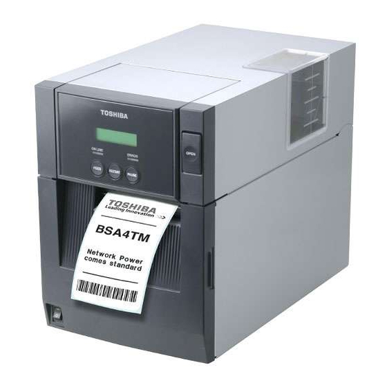
Page 4: Appearance And Dimensions (Approximate)
1. OUTLINE EO10-33016A 1.3 Appearance and Dimensions (Approximate) 1.3 Appearance and Dimensions (Approximate) 1.3.1 Front View/Rear View Front View Rear View Top Cover Supply Window Ribbon Cover LCD Message Serial Interface Display (Option), Wireless LAN Operation interface (Option) Panel Media Outlet Parallel Interface Connector (Centronics) Power Switch... -
Page 5: Basic Specifications
1. OUTLINE EO10-33016A 1.4 Basic Specifications 1.4 Basic Specifications 1) Printing method: Thermal direct printing or thermal transfer printing 2) Print head GS12 model TS12 model Total number of dots 832 dots 1248 dots Dot density 8 dots/mm 11.8 dots/mm Effective print width 104 mm 105.7 mm... - Page 6 1. OUTLINE EO10-33016A 1.4 Basic Specifications Magnification of bar code UPC/EAN/JAN/CODE93/128/PDF417.... Up to 6 modules can be automatically calculated using 1-module width designation (1 to 15 dots). Dots/Module Bar code UPC-A/E 0.25 0.38 0.50 0.63 – – – Min. Module Width (mm) EAN8/13 0.76 1.14...
- Page 7 1. OUTLINE EO10-33016A 1.4 Basic Specifications 12) White or black background all types of characters are available. ° ° ° ° 13) Character rotation: , 90 , 180 , 270 ° ° ° ° 14) Character strings rotation: 0 , 90 , 180 , 270 15) Type of line...
- Page 8 1. OUTLINE EO10-33016A 1.4 Basic Specifications (3) Auto cut mechanism (Option) When an optional cutter module is attached, printed media is fed to the cutter unit and cut off from the media roll. Tag Stock Cutter Black Mark Sensor 18) Power supply AC100 to 240 V ±10%, 50/60Hz Universal power supply: Harmonics:...
-
Page 9: Electronics Specifications
1. OUTLINE EO10-33016A 1.5 Electronics Specifications 1.5 Electronics Specifications 1) CPU: HD6417705F133BV 2) Memory (1) Program: 16-MB Flash ROM (2) Backup: 512-byte EE-PROM (3) Image buffer + Work: 16-MB SD-RAM 3) Interface (1) Parallel interface (Standard interface) Centronics interface conforming to IEEE1284, supporting SPP mode (compatibility mode) and nibble mode. - Page 10 1. OUTLINE EO10-33016A 1.5 Electronics Specifications Pin Layout (IEEE1284-B Connector) Signal SPP Mode Nibble Mode nStrobe HostClk Data 1 Data 1 Data 2 Data 2 Data 3 Data 3 Data 4 Data 4 Data 5 Data 5 Data 6 Data 6 Data 7 Data 7 Data 8...
- Page 11 1. OUTLINE EO10-33016A 1.5 Electronics Specifications Input/Output Signals SPP mode Signal Description Data1 to 8 Input Input data signals for the 1st to 8th bits. Logic 1 is “High” level. Min. data pulse width of 2.5 µsec. nStrobe Input Synchronizing signal for reading the above data. Normally at “High”...
- Page 12 1. OUTLINE EO10-33016A 1.5 Electronics Specifications Select Output This is an output signal which indicates whether the printer is in Pause state or placed online. The printer can receive data while placed online. The signal is at “Low” level while the printer is in a Pause state. The signal is kept at “Low”...
- Page 13 1. OUTLINE EO10-33016A 1.5 Electronics Specifications HostBusy Input Reverse data transfer phase: It indicates that the host can receive data from the printer by setting the signal to low. Then, the host sets the signal to high, and sends the Ack indicating that the nibble data is received.
- Page 14 1. OUTLINE EO10-33016A 1.5 Electronics Specifications (2) USB (Standard interface) Standard: Conforming to Rev. 2.0 Transfer type: Control transfer, Bulk transfer Transfer rate: Full speed (12M bps) Transfer control method: Data transfer is controlled by sending/receiving a status with the receive buffer free space information.
- Page 15 1. OUTLINE EO10-33016A 1.5 Electronics Specifications Flow control XON/XOFF (DC1/DC3) protocol This is a software flow control using XON (DC1)/XOFF (DC3) code. • When initialized after power on, this printer becomes ready to receive data and sends an XON code (11H). (Transmission or non-transmission of XON code is selectable by means of the parameter setting.) •...
- Page 16 1. OUTLINE EO10-33016A 1.5 Electronics Specifications READY/BUSY (RTS) Protocol This is a hardware flow control using RTS signal as a control code. • When initialized after power on, this printer becomes ready to receive data and converts the RTS signal to "High" level (READY). •...
- Page 17 Printer COM1 Photo-coupler TPL521 (TOSHIBA) TLP521 (TOSHIBA) There are six input circuits, and each input is a current loop using a photo-coupler. The anode of the photo-coupler is connected to common pin COM1 in each of the six circuits. Each cathode is independent.
- Page 18 1. OUTLINE EO10-33016A 1.5 Electronics Specifications 4) Sensor/switch (1) Media sensor This sensor is comprised of the black mark sensor and feed gap sensor. It is positioned 92.1 mm from the platen. The sensor position is adjustable according to the black mark position. It can be manually moved from the center to the left edge of media.
- Page 19 1. OUTLINE EO10-33016A 1.5 Electronics Specifications (2) Slit sensor (Transmissive sensor) The ribbon motor block has three same slit sensors: Two of them are attached to the ribbon feed motor side, and the other one is to the ribbon take-up side. A slit sensor is a photo-coupler, consisting of an LED and a transistor.
- Page 20 1. OUTLINE EO10-33016A 1.5 Electronics Specifications (4) Front cover open sensor On the right side of the printer front, a front cover open sensor is provided. This sensor is a photo-coupler, consisting of an LED and a transistor. A front cover open status is detected depending on the tab of the front cover intercepts the photo-coupler or not.
- Page 21 1. OUTLINE EO10-33016A 1.5 Electronics Specifications (6) Cutter home position sensor for optional cutter module This sensor is positioned inside of the cutter unit. This is a photo-coupler, consisting of an LED and a transistor. When the arm linked with the cutter blade intercepts the photo-coupler, it is considered as a cutter home position.
-
Page 22: Supply Specifications
Detail specifications and other information on the media and ribbon are described in Supply Manual by model. It is issued by and sent from TOSHIBA TEC H.Q (Sales Division) upon release of new model or manual's revision. When purchasing the supplies locally, be sure to refer to the Supply Manual for details. - Page 23 2. SUPPLY SPECIFICATIONS EO10-33016A 2.1 Media NOTES: To ensure print quality and print head life use only TOSHIBA TEC specified media. The ratio of a label length to a gap length must be a minimum of 3 to 1 (3:1).
- Page 24 2. SUPPLY SPECIFICATIONS EO10-33016A 2.1 Media (2) Specification of a Gap or a Black Mark • Feed Gap Sensor and a Gap Centre of media Area to be detected Sensor position Print side Label Min. 2.0 mm Label Min. 12 mm Media feed direction Sensor is movable within this range.
- Page 25 2. SUPPLY SPECIFICATIONS EO10-33016A 2.1 Media (3) Effective Printing Area • Relationship between the head effective print width and paper Out of print range Out of print range Head Effective Print Range 104.0 mm (GS model) 105.7 mm (TS model) 118 mm (Max.
-
Page 26: Ribbon
The ink side faces outside of ribbon winding NOTES: 1. To ensure print quality and print head life use only TOSHIBA TEC specified ribbons. 2. Too much difference in width between media and ribbon may cause ribbon wrinkles. To avoid ribbon wrinkles use a ribbon for proper media width shown in the above table. -
Page 27: Care And Handling Of The Media And Ribbon
2. SUPPLY SPECIFICATIONS EO10-33016A 2.3 Care and Handling of the Media and Ribbon (3) Appearance of Ribbon This inked surface faces the outside This ribbon should be wound at center of the core. End tape (Non transmissive) Ink ribbon Leader tape Adhesive tape Adhesive tape Adhesive tape... -
Page 28: Specification Of Rfid Tag
Printers, which are equipped with an RFID kit, can print data on the surface of RFID tags as well as write data on them. The B-SA4T series optional RFID kit, B-SA704-RFID-U2-EU-R, is destined for Europe and operates in the UHF band 869.7MHz to 870.0MHz ( Center Frequency : 869.85MHz). - Page 29 2. SUPPLY SPECIFICATIONS EO10-33016A (Revision Date: Feb. 14, 2008) 2.4 Specification of RFID Tag (1) UPM Raflatac’s Rafsec Short Dipole 2 Tag It is recommended to locate the vertical center of an RFID tag at 27 mm ± 3 mm from a leading edge of a label and align the horizontal center with the horizontal center of the label.
- Page 30 2. SUPPLY SPECIFICATIONS EO10-33016A (Revision Date: Feb. 14, 2008) 2.4 Specification of RFID Tag (2) UPM Raflatac’s Rafsec WEB Tag It is recommended to locate the vertical center of an RFID tag at 58 mm ± 6 mm from a leading edge of a label and align the horizontal center with the horizontal center of the label.
- Page 31 2. SUPPLY SPECIFICATIONS EO10-33016A (Revision Date: Feb. 14, 2008) 2.4 Specification of RFID Tag 2.4.4 Short-pitch tag (Rafsec Short Dipole2) A Shield Sheet is supplied with the B-SA704-RFID-U2-EU-R to enable the RFID kit to encode short-pitch tags properly. When the Shield Sheet is attached to the printer, the write field will be narrower. The RFID kit is designed so that the second label is positioned just above the antenna while the first label is at the print start position, when using the following short-pitch label.
- Page 32 2. SUPPLY SPECIFICATIONS EO10-33016A (Revision Date: Feb. 14, 2008) 2.4 Specification of RFID Tag 2.4.5 Cautions for using RFID Tags (1) Damage to Thermal Head by RFID Chip The thermal head may be damaged when it passes over an RFID tag chip. Our endurance test using TOPPAN’s Class 1 Generation 2 labels proved that issuing 1,200,000 labels did not damage the thermal head.
- Page 33 2. SUPPLY SPECIFICATIONS EO10-33016A (Revision Date: Feb. 14, 2008) 2.4 Specification of RFID Tag 2.4.6 Printing on Bump (Chip/Antenna) Area Embedding RFID tags in labels creates bumps in a chip/antenna area in the labels, causing incomplete printing. Especially, in the areas 5 mm from and left and right sides of the RFID-tag embedded area shown in the figure below, uneven printing or incomplete printing can occur easily.
- Page 34 2. SUPPLY SPECIFICATIONS EO10-33016A (Revision Date: Feb. 14, 2008) 2.4 Specification of RFID Tag 2.4.9 Caution for Minimum Label Pitch Length When media, of which label pitch length is short, is used, data may be written on an RFID tag next to the target RFID tag.
- Page 35 2. SUPPLY SPECIFICATIONS EO10-33016A (Revision Date: Feb. 14, 2008) 2.4 Specification of RFID Tag (3) Adjustment of location of antenna When writing data on tags, especially on short-pitch tags, the antenna may communicate with non- target tags, and this lowers the write rate. The B-SA4T has a feature to pinpoint a target tag by evaluating the output power (AGC) of tags.
-
Page 36: Optional Kit
Installing this board in the printer allows a connection with Board an external device with the exclusive interface. Real Time Clock B-SA704-RTC-QM-R This module holds the current time: year, month, day, hour, minute, second NOTE: To purchase the optional kits, please contact the TOSHIBA TEC Head Quarters. 3- 1... -
Page 37: Strip Module: B-Sa904-H-Qm-R
3. OPTIONAL KIT EO10-33016A 3.2 Strip Module: B-SA904-H-QM-R 3.1 Cutter Module: B-SA204-QM/B-SA204-QM-R/B-SA204P-QM-R Item Specification Cutting method Guillotine cutter Media to be cut Thermal paper, normal paper, label stock Media thickness 80 to 290µm DC24V ±5% Rated voltage Cutter life 80 to 160mm-thick paper: 1000000 cuts 160 to 290mm-thick paper: 500000 cuts Operating environment Temperature... -
Page 38: Serial Interface Board: B-Sa704-Rs-Qm-R
3. OPTIONAL KIT EO10-33016A 3.2 Strip Module: B-SA904-H-QM-R 3.3 Serial Interface Board: B-SA704-RS-QM-R Item Specification Type RS-232C Communication mode Full duplex Transmission speed 2400 bps, 4800 bps, 9600 bps, 19200 bps, 38400 bps, 115200 bps Synchronization Start-stop synchronization Start bit 1 bit Stop bit 1 bit, 2 bit... -
Page 39: Wireless Lan Board: B-Sa704-Wlan-Qm
3. OPTIONAL KIT EO10-33016A 3.4 Wireless LAN Board: B-SA704-WLAN-QM 3.4 Wireless LAN Board: B-SA704-WLAN-QM Hardware Specification Item Specification Wired LAN part Connected to a wired LAN port of the printer. Wireless LAN part IEEE802.11a Transfer mode Conforming to IEEE802.11a Orthogonal Frequency-Division Multiplexing (OFDM) Channel Depending on countries... - Page 40 3. OPTIONAL KIT EO10-33016A 3.4 Wireless LAN Board: B-SA704-WLAN-QM Country code As available frequency bands are different from country to country, be sure to set a country code before installing a wireless LAN module in a user’s printer. Also, ask an end user to confirm a country code.
- Page 41 3. OPTIONAL KIT EO10-33016A 3.4 Wireless LAN Board: B-SA704-WLAN-QM NOTE: MAC address can be checked by using “arp -a” command on MS-DOS Prompt. <Example> The following screen shows an example of executing an arp –a command on MS-DOS Prompt. After wireless LAN board (default IP address: 192.168.10.21) is pinged, IP address and MAC address are displayed.
- Page 42 3. OPTIONAL KIT EO10-33016A 3.4 Wireless LAN Board: B-SA704-WLAN-QM <Downloading the firmware> Status LAN status LED1 Blink at the same time Firmware is being overwritten. LED2 LED3 <Error> Status LAN status LED2 Blink Wired LAN error LED3 Blink Wireless LAN error Certification The wireless LAN module complies with the following standards.
-
Page 43: 300-Dpi Print Head: B-Sa704-Tph3-Qm-R
NOTES: 1. Do not touch the print head by bare hands. 2. Use TOSHIBA TEC approved media only. 3. Do not perform printing when the printer built up dew condensation. 4. Use a print head cleaner or a cotton swab or soft cloth slightly moistened with absolute ethyl alcohol to clean the print head element. -
Page 44: Expansion I/O Board: B-Sa704-Io-Qm-R
3. OPTIONAL KIT EO10-33016A (Revision Date: Jan. 19, 2006) 3.7 Expansion I/O Board: B-SA704-IO-QM-R 3.7 Expansion I/O Board: B-SA704-IO-QM-R Item Specification IN0 − IN5 Input Signal OUT0 − OUT6 Output Signal Connector (External FCN-781P024-G/P or equivalent Device Side) Connector (Printer Side) FCN-685J0024 or equivalent Signal Function... -
Page 45: Rfid Module: B-Sa704-Rfid-U2-Eu-R
3. OPTIONAL KIT EO10-33016A (Revision Date: Feb. 14, 2008) 3.8 RFID Module: B-SA704-RFID-U2-EU-R 3.8 RFID Module: B-SA704-RFID-U2-EU-R Item Specification Module TOSHIBA TEC TRW-EUM-01 for Europe Applicable standard ETSI EN 300 220 Frequency range 869.7-870.0MHz Center frequency 869.85MHz Output power (ERP) Max.