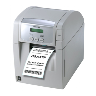
Toshiba B-SA4TP SERIES Owner's Manual
Barcode printer
Hide thumbs
Also See for B-SA4TP SERIES:
- Owner's manual (114 pages) ,
- Instructions manual (9 pages) ,
- Option installation manual (58 pages)

Related Manuals for Toshiba B-SA4TP SERIES


Summary of Contents for Toshiba B-SA4TP SERIES
- Page 1 TOSHIBA Barcode Printer B-SA4TP SERIES Owner’s Manual Mode d’emploi Bedienungsanleitung Manual de instrucciones Gebruikershandleiding Manuale Utente Manual do Utilizador...
- Page 2 Canada.” (for CANADA only) N258 IP20 Copyright © 2005 < For EU Only > by TOSHIBA TEC CORPORATION TOSHIBA TEC Europe Retail Information Systems S.A. All Rights Reserved 570 Ohito, Izunokuni-shi, Shizuoka-ken, JAPAN Rue de la Célidée 33 BE-1080 Brussels...
- Page 3 TOSHIBA Barcode Printer B-SA4TP SERIES Owner's Manual...
- Page 4 Waste Recycling information for users: Following information is only for EU-member states: The use of the crossed-out wheeled bin symbol indicates that this product may not be treated as general household waste. By ensuring this product is disposed of correctly you will help prevent potential negative consequences for the environment and human health, which could otherwise be caused by inappropriate waste handling of this product.
- Page 5 If the product is used in the countries or areas other than the following, you may be punished according to the laws of those countries or areas. Hereby, Toshiba TEC Corporation, declares that this TRW-EUM-01 (B-SA704-RFID-U2-EU-R) is in compliance with the essential requirements and other relevant provisions of Directive 1999/5/EC.
- Page 6 Do not attempt to effect repairs or modifications to this equipment. If a fault occurs that cannot be rectified using the procedures described in this manual, turn off the power, unplug the machine, then contact your authorised TOSHIBA TEC representative for assistance. Meanings of Each Symbol This symbol indicates warning items (including cautions).
- Page 7 • Utilize our maintenance services. After purchasing the machine, contact your authorised TOSHIBA TEC representative for assistance once a year to have the inside of the machine cleaned. Otherwise, dust will build up inside the machines and may cause a fire or a malfunction. Cleaning is particularly effective before humid rainy seasons.
-
Page 8: Table Of Contents
ENGLISH VERSION EO1-33048 TABLE OF CONTENTS Page PRODUCT OVERVIEW......................E1- 1 Introduction........................E1- 1 Features ........................E1- 1 Accessories ......................... E1- 2 Appearance ........................E1- 3 1.4.1 Dimensions........................E1- 3 1.4.2 Front View .........................E1- 3 1.4.3 Rear View ........................E1- 3 1.4.4 Operation Panel......................E1- 4 1.4.5 Interior ........................E1- 4 Options ..........................E1- 5 PRINTER SETUP ........................ - Page 9 CAUTION! 1. This manual may not be copied in whole or in part without prior written permission of TOSHIBA TEC. 2. The contents of this manual may be changed without notification.
-
Page 10: Product Overview
ENGLISH VERSION EO1-33048 1.1 Introduction 1. PRODUCT OVERVIEW Thank you for choosing the TOSHIBA B-SA4TP series thermal printer. 1.1 Introduction This Owner’s Manual contains from general set-up through how to confirm the printer operation using an online test print, and should be read carefully to help gain maximum performance and life from your printer. -
Page 11: Accessories
1. PRODUCT OVERVIEW ENGLISH VERSION EO1-33048 1.3 Accessories When unpacking the printer, please make sure all the following Accessories accessories are supplied with the printer. Start-up CD-ROM (1 pc.) NOTE: As a power cord is not supplied <Contents> • Bar code print application (Bartender ultra lite) with this printer, please purchase •... -
Page 12: Appearance
1. PRODUCT OVERVIEW ENGLISH VERSION EO1-33048 1.4 Appearance The names of the parts or units introduced in this section are used in the 1.4 Appearance following chapters. 238 (9.4) 339 (13.3) 1.4.1 Dimensions (13.1) Dimensions in mm (inches) 1.4.2 Front View Ribbon Cover Top Cover LCD Message... -
Page 13: Operation Panel
1. PRODUCT OVERVIEW ENGLISH VERSION EO1-33048 1.4 Appearance 1.4.4 Operation Panel LCD Message Display ON LINE LED ERROR LED (Green) (Red) [PAUSE] key [FEED] key [RESTART] key Please see Section 3.1 for further information about the Operation Panel. 1.4.5 Interior Ribbon Cover Supply Path Label WARNING! -
Page 14: Options
1. PRODUCT OVERVIEW ENGLISH VERSION EO1-33048 1.5 Options Options Option Name Type Usage 300-dpi Print B-SA704-TPH3-QM-R This print head enables a conversion of a 203-dpi print head of the Head B-SA4TM-GS12/B-SA4TP-GS12 model into a 300-dpi print head. This option is intended for use when you desire to print Kanji (Chinese characters) or to obtain clearer print. -
Page 15: Printer Setup
2. PRINTER SETUP ENGLISH VERSION EO1-33048 2. PRINTER SETUP 2. PRINTER SETUP This section outlines the procedures to setup your printer prior to its operation. The section includes precautions, loading media and ribbon, connecting cables, setting the operating environment of the printer, and performing an online print test. -
Page 16: Installation
2. PRINTER SETUP ENGLISH VERSION EO1-33048 2.2 Connecting the Power Cord To insure the best operating environment, and to assure the safety of the 2.1 Installation operator and the equipment, please observe the following precautions. • Operate the printer on a stable, level, operating surface in a location CAUTION! free from excessive humidity, high temperature, dust, vibration or A s the enclosure of this product... -
Page 17: Loading The Media
2. PRINTER SETUP ENGLISH VERSION EO1-33048 2.3 Loading the Media The following procedure shows the steps to properly load the media into 2.3 Loading the Media the printer so that it feeds straight and true through the printer. Use the same procedure when replacing the media, also. WARNING! The printer prints both labels and tags. - Page 18 2. PRINTER SETUP ENGLISH VERSION EO1-33048 2.3 Loading the Media 5. Put the Media Holder (Left) onto the Media Shaft. Push the Media 2.3 Loading the Media Holder (Left) and the Media Holder (Right) against the media until the (Cont.) media is held firmly in place.
- Page 19 2. PRINTER SETUP ENGLISH VERSION EO1-33048 2.3 Loading the Media Pull the media out of the front of the printer, and adjust the Media 2.3 Loading the Media Guides to the media width. This will automatically centre the media. (Cont.) Media Guide CAUTION! 1.
- Page 20 2. PRINTER SETUP ENGLISH VERSION EO1-33048 2.3 Loading the Media 11. After loading the media, it may be necessary to set the position of 2.3 Loading the Media the Media Sensor used to detect the print start position for label or (Cont.) tag printing.
- Page 21 2. PRINTER SETUP ENGLISH VERSION EO1-33048 2.3 Loading the Media Setting the Black Mark Sensor position 2.3 Loading the Media (Cont.) When using media with black marks, the Black Mark Sensor is used to detect a print start position. (1) Push the Upper Sensor Lever inside and open the Upper Sensor NOTES: Ass’y.
- Page 22 2. PRINTER SETUP ENGLISH VERSION EO1-33048 2.3 Loading the Media 12. There are three issue modes available on this printer. How to set the 2.3 Loading the Media media for each mode is provided below. (Cont.) Batch mode In the batch mode, the media is continuously printed and fed until the number of labels/tags specified in the issue command have been printed.
- Page 23 2. PRINTER SETUP ENGLISH VERSION EO1-33048 2.3 Loading the Media (2) Press down the Release Bar to open the Strip Unit. 2.3 Loading the Media Release Bar (Cont.) Strip Unit (3) Remove enough labels from the leading edge of the media to leave 300mm of backing paper free.
- Page 24 2. PRINTER SETUP ENGLISH VERSION EO1-33048 2.3 Loading the Media 2.3 Loading the Media Cut mode (Option) (Cont.) When the optional Cutter Module is fitted, the media is automatically cut. WARNING! Insert the leading edge of the media into the Media Outlet of the Cutter Module.
-
Page 25: Loading The Ribbon
2. PRINTER SETUP ENGLISH VERSION EO1-33048 2.4 Loading the Ribbon There are two types of media available for printing on: these are thermal 2.4 Loading the Ribbon transfer media (normal media) and direct thermal media (with a chemically treated surface). DO NOT LOAD a ribbon when using a WARNING! direct thermal media. - Page 26 2. PRINTER SETUP ENGLISH VERSION EO1-33048 2.4 Loading the Ribbon ° 3. Lower the Top Cover to its 45 angle open position. While pushing 2.4 Loading the Ribbon the Top Cover Stopper, raise the Top Cover again. This will fix the (Cont.) Top Cover.
- Page 27 2. PRINTER SETUP ENGLISH VERSION EO1-33048 2.4 Loading the Ribbon 7. Close the Ribbon Cover until it clicks. 2.4 Loading the Ribbon (Cont.) Ribbon Cover WARNING! Be sure to close the Ribbon Cover before closing the Top Cover. It is dangerous to close the Top Cover with the Ribbon Cover opened, as the Ribbon Top Cover...
-
Page 28: Connecting The Printer To Your Host Computer
2. PRINTER SETUP ENGLISH VERSION EO1-33048 2.5 Connecting the Printer to Your Host Computer The following paragraphs outline how to connect your host computer to 2.5 Connecting the the printer, and will also show how to make cable connections to other Printer to Your Host devices. -
Page 29: Turning The Printer On
2. PRINTER SETUP ENGLISH VERSION EO1-33048 2.6 Turning the Printer ON When the printer is connected to your host computer it is good practice to 2.6 Turning the Printer turn the printer ON before turning on your host computer and turn OFF your host computer before turning off the printer. -
Page 30: Setting An Operating Environment
TOSHIBA TEC service representative. For the settings this manual does not cover, please contact your nearest TOSHIBA TEC service representative, or refer to the B-SA4T Series Key Operation Specification stored in the CD-ROM. How to enter the System Mode... -
Page 31: Parameter Setting
2. PRINTER SETUP ENGLISH VERSION EO1-33048 2.7 Setting an Operating Environment While “<2>PARAMETER SET” is displayed on the LCD Message 2.7.1 Parameter Setting Display, press the [PAUSE] key to enter the Parameter Setting Mode. The Parameter Setting Mode contains the following sub menus. Each time the [PAUSE] key is pressed, the sub menus are displayed sequentially. - Page 32 2. PRINTER SETUP ENGLISH VERSION EO1-33048 2.7 Setting an Operating Environment (1) Character Code Selection 2.7.1 Parameter Setting This parameter is to choose a character code used for printing. Printed (Cont.) characters differ depending on a chosen character code and font. For details of characters, refer to the B-SA4T Series External Equipment Interface Specification (Printer Command Manual).
- Page 33 2. PRINTER SETUP ENGLISH VERSION EO1-33048 2.7 Setting an Operating Environment (3) Baud Rate Selection 2.7.1 Parameter Setting This parameter is to choose a baud rate of the RS-232C interface. When (Cont.) the printer communicates with a host computer by serial interface, be sure to match the setting with the host.
- Page 34 2. PRINTER SETUP ENGLISH VERSION EO1-33048 2.7 Setting an Operating Environment (5) Stop Bit Length Selection 2.7.1 Parameter Setting This parameter is to choose a stop bit length of the RS-232C interface. (Cont.) Be sure to match a setting with a host computer. When “<2>PARAMETER SET”...
- Page 35 2. PRINTER SETUP ENGLISH VERSION EO1-33048 2.7 Setting an Operating Environment (8) LCD Language Selection 2.7.1 Parameter Setting This parameter is to choose a language in which the LCD message is (Cont.) displayed. When “<2>PARAMETER SET” appears, press the [PAUSE] key until the following display appears.
- Page 36 2. PRINTER SETUP ENGLISH VERSION EO1-33048 2.7 Setting an Operating Environment When ON is selected, pressing the [PAUSE] key will result that the LCD 2.7.1 Parameter Setting Message Display shows the stop position fine adjustment value setting (Cont.) screen. <2>PARAMETER SET POSITION +0.0mm POSITION +5.0mm [RESTART]...
- Page 37 2. PRINTER SETUP ENGLISH VERSION EO1-33048 2.7 Setting an Operating Environment After setting the control code for Control Code 1, press the [PAUSE] 2.7.1 Parameter Setting key to show the CONTROL CODE2 screen. In a same manner, press the (Cont.) [PAUSE] key after setting the control code for Control Code 2 to display the CONTROL CODE3 screen.
- Page 38 2. PRINTER SETUP ENGLISH VERSION EO1-33048 2.7 Setting an Operating Environment (13) KANJI Code Selection 2.7.1 Parameter Setting This parameter is to choose a KANJI code. (Cont.) When “<2>PARAMETER SET” appears, press the [PAUSE] key until the following display appears. NOTE: Kanji code selection is not supported <2>PARAMETER SET...
- Page 39 2. PRINTER SETUP ENGLISH VERSION EO1-33048 2.7 Setting an Operating Environment (15) Auto Print Head Check Selection 2.7.1 Parameter Setting This parameter is to choose whether to perform the Auto Print Head (Cont.) Check function at the power on time. When “<2>PARAMETER SET” appears, press the [PAUSE] key until the following display appears.
- Page 40 2. PRINTER SETUP ENGLISH VERSION EO1-33048 2.7 Setting an Operating Environment (17) Web Printer Function Selection 2.7.1 Parameter Setting This parameter is to choose whether to use the printer as a web printer. (Cont.) When “<2>PARAMETER SET” appears, press the [PAUSE] key until the following display appears.
- Page 41 2. PRINTER SETUP ENGLISH VERSION EO1-33048 2.7 Setting an Operating Environment (19) Ribbon Near End Selection 2.7.1 Parameter Setting This parameter is to choose the remaining ribbon length where the ribbon (Cont.) near end is detected. When “<2>PARAMETER SET” appears, press the [PAUSE] key until the following display appears.
- Page 42 2. PRINTER SETUP ENGLISH VERSION EO1-33048 2.7 Setting an Operating Environment (21) Plug & Play Selection 2.7.1 Parameter Setting This parameter is to choose whether to enable a Plug & Play function. (Cont.) When “<2>PARAMETER SET” appears, press the [PAUSE] key until the following display appears.
- Page 43 2. PRINTER SETUP ENGLISH VERSION EO1-33048 2.7 Setting an Operating Environment (23) Pre-Strip Selection 2.7.1 Parameter Setting This parameter is to choose whether to activate the Pre Strip function. (Cont.) When this parameter is set to ON (Available), the top edge of a label is separated (pre-stripped) from the backing paper before the label is printed.
- Page 44 2. PRINTER SETUP ENGLISH VERSION EO1-33048 2.7 Setting an Operating Environment (24) Reverse Feed Speed Selection 2.7.1 Parameter Setting This parameter is to choose a reverse feed speed. (Cont.) In the strip issue, the back feed speed of 3”/sec. may cause a shortage of feed amount due to a lack of torque, slippery media surface, etc.
- Page 45 2. PRINTER SETUP ENGLISH VERSION EO1-33048 2.7 Setting an Operating Environment (26) Keyboard Interface Selection 2.7.1 Parameter Setting This parameter is to choose a keyboard interface. (Cont.) When “<2>PARAMETER SET” appears, press the [PAUSE] key until the following display appears. <2>PARAMETER SET KB I/F Use the [FEED] or [RESTART] key to select a desired option.
-
Page 46: Dump Mode Setting
2. PRINTER SETUP ENGLISH VERSION EO1-33048 2.7 Setting an Operating Environment While “<4>DUMP MODE” is displayed on the LCD Message Display, 2.7.2 Dump Mode Setting press the [PAUSE] key to enter the Dump Mode. In the Dump Mode, data in the receive buffer are printed. Data are expressed in hexadecimal values. -
Page 47: Feed Direction
2. PRINTER SETUP ENGLISH VERSION EO1-33048 2.7 Setting an Operating Environment The data in the receive buffer is printed as follows: 2.7.2 Dump Mode Setting (Cont.) 00 00 00 00 00 00 00 00 00 00 00 00 00 00 00 00 00 00 00 00 00 00 00 00 00 00 00 00 00 00 00 00 00 00 00 00 00 00 00 00 00 00 00 00 00 00 00 00 7B 41 58 3B 2B 30 30 30 2C 2B 30 30 30 2C 2B 30... -
Page 48: Basic Expansion Mode
2. PRINTER SETUP ENGLISH VERSION EO1-33048 2.7 Setting an Operating Environment While “<5>EXPAND MDOE” is displayed on the LCD Message Display, 2.7.3 BASIC Expansion Mode press the [PAUSE] key to enter the BASIC Expansion Mode. In the BASIC Expansion Mode, it is possible to execute the BASIC NOTE: expansion mode program under the following conditions. -
Page 49: Automatic Calibration
2. PRINTER SETUP ENGLISH VERSION EO1-33048 2.7 Setting an Operating Environment While “<6>AUTO CALIB” is displayed on the LCD Message Display, 2.7.4 Automatic Calibration press the [PAUSE] key to enter the Automatic Calibration Mode. In the Automatic Calibration Mode, whether to activate the automatic calibration at a power on time or not is selectable. -
Page 50: Lan Setting
2. PRINTER SETUP ENGLISH VERSION EO1-33048 2.7 Setting an Operating Environment While “<7>LAN” is displayed on the LCD Message Display, press the 2.7.5 LAN Setting [PAUSE] key to enter the LAN Setting Mode. In the LAN Setting Mode, whether to enable the LAN communication and SNMP or not is selectable. -
Page 51: Real Time Clock Setting
2. PRINTER SETUP ENGLISH VERSION EO1-33048 2.7 Setting an Operating Environment While “<8>RTC SET” is displayed on the LCD Message Display, press 2.7.6 Real Time Clock Setting the [PAUSE] key to enter the Real Time Clock Setting Mode. NOTE: The Real Time Clock Setting Mode contains the following sub menus. The Real Time Clock Setting is Each time the [PAUSE] key is pressed, the sub menus are displayed effective only when an optional Real... - Page 52 2. PRINTER SETUP ENGLISH VERSION EO1-33048 2.7 Setting an Operating Environment (3) Low Battery Check Setting 2.7.6 Real Time Clock Setting This parameter is to choose whether to activate the low battery check (Cont.) function or not. <8>RTC SET NOTE: LOW BATT.
-
Page 53: Ip Address Setting (Tcp/Ip)
2. PRINTER SETUP ENGLISH VERSION EO1-33048 2.7 Setting an Operating Environment When the printer is connected to a PC through TCP/IP by using a LAN 2.7.7 IP Address Setting cable, it is necessary to set an IP address in the System Mode for system (TCP/IP) administrators. -
Page 54: Ip Address Setting
2. PRINTER SETUP ENGLISH VERSION EO1-33048 2.7 Setting an Operating Environment In this section, how to set the IP address is described. 2.7.7 IP Address Setting First, you need to access the System Mode for system administrators. (TCP/IP) (Cont.) 1. While holding down the [FEED] and [PAUSE] keys, turn on the printer. - Page 55 2. PRINTER SETUP ENGLISH VERSION EO1-33048 2.7 Setting an Operating Environment (1) Printer IP Address 2.7.7 IP Address Setting This parameter is to set an IP address. (TCP/IP) (Cont.) <7>IP ADDRESS NOTES: PRINTER IP ADRES 1. Set each 3-digit value by using [PAUSE] the [RESTART] or [FEED] key.
- Page 56 2. PRINTER SETUP ENGLISH VERSION EO1-33048 2.7 Setting an Operating Environment (3) Subnet Mask 2.7.7 IP Address Setting This parameter is to set a Subnet Mask. (TCP/IP) (Cont.) <7>IP ADDRESS NOTE: SUBNET MASK After the last 3-digit value is set, [PAUSE] press the [PAUSE] key to go to Socket Port Setting.
- Page 57 2. PRINTER SETUP ENGLISH VERSION EO1-33048 2.7 Setting an Operating Environment (5) DHCP 2.7.7 IP Address Setting This parameter is to enable DHCP. (TCP/IP) (Cont.) <7>IP ADDRESS NOTE: DHCP Pressing the [PAUSE] key while “DHCP ON” is displayed allows [PAUSE] [RESTART] or [FEED] you to set a DHCP client ID.
- Page 58 Upper 4 bits Lower 4 bits “ & ‘ < > SP = Space (Example) To enter “TOSHIBA” in Hex. code: 54 4F 53 48 49 42 41 When the system mode settings have been completed, turn off the printer. E2-44...
-
Page 59: Installing The Printer Drivers
Installing the Printer Drivers 2.8.1 Introduction This manual describes how to install the TOSHIBA printer driver for the TOSHIBA bar code printer on your Windows host computer; install and delete the printer driver, the procedure for adding the LAN port, cautions and limitations. - Page 60 2. PRINTER SETUP ENGLISH VERSION EO1-33048 2.8 Installing the Printer Drivers Windows 98/Me Select “Settings” – “Printers” from the “Start” menu to open the printer folder. (2) Double-click on the “Add Printer” icon. The Add Printer Wizard runs. Click on the [Next] button. (3) Select “Local printer”, then click on the [Next] button.
- Page 61 2. PRINTER SETUP ENGLISH VERSION EO1-33048 2.8 Installing the Printer Drivers (6) The screen to select the existing installed printer driver or use the new one, is displayed. Select “Replace existing driver”, then click on the [Next] button. If you install the printer driver for the first time, this screen is not displayed.
- Page 62 2. PRINTER SETUP ENGLISH VERSION EO1-33048 2.8 Installing the Printer Drivers Windows 2000/XP (1) Log on to your host computer as a member who has full control access privilege concerning the printer settings. (2) Select “Settings” – “Printers” from the “Start” menu to open the printer folder. (3) Double-click on the “Add Printer”...
- Page 63 2. PRINTER SETUP ENGLISH VERSION EO1-33048 2.8 Installing the Printer Drivers (9) The “Use Existing Driver” screen is displayed. Select “Replace existing driver”, then click on the [Next] button. If you install the printer driver for the first time, this screen is not displayed. (10) Change the printer name if necessary, and select whether or not you use the printer as the default printer (“Yes”...
- Page 64 2. PRINTER SETUP ENGLISH VERSION EO1-33048 2.8 Installing the Printer Drivers (2) USB INTERFACE Installation starts by the operating system’s plug-and-play function. Windows 98/Me (1) Turn the printer ON, then connect it to your host computer with the USB cable. The “New Hardware Found”...
- Page 65 2. PRINTER SETUP ENGLISH VERSION EO1-33048 2.8 Installing the Printer Drivers (3) Select “Search for the best driver for your device. (Recommended)”. Mark the “Specify a location” checkbox, then click on the [Browse] button. Specify “\driver” folder, then click on the [Next] button. (4) Check to see that the “USB Printing Support”...
- Page 66 2. PRINTER SETUP ENGLISH VERSION EO1-33048 2.8 Installing the Printer Drivers (5) When the screen which indicates the USB Printing Support driver has been installed, is displayed, click on the [Finish] button. (6) After a while, “TEC B-SA4T” is detected as a new hardware. (7) The “Add New Hardware Wizard”...
- Page 67 2. PRINTER SETUP ENGLISH VERSION EO1-33048 2.8 Installing the Printer Drivers (8) Select “Search for the best driver for your device. (Recommended)”. Mark the “Specify a location” checkbox, then click on the [Browse] button. Specify “\driver” folder, then click on the [Next] button. (9) Check to see that the “TEC B-SA4T”...
- Page 68 2. PRINTER SETUP ENGLISH VERSION EO1-33048 2.8 Installing the Printer Drivers (10) Change the printer name if necessary, and select whether or not you use the printer as the default printer (“Yes” or “No”). Click on the [Finish] button. (11) When the screen, which indicates TEC B-SA4T has been installed, is displayed, click on the [Finish] button.
- Page 69 2. PRINTER SETUP ENGLISH VERSION EO1-33048 2.8 Installing the Printer Drivers Windows 2000/XP NOTE: When plug-and-play printer installation in progress is stopped, be sure to delete the printer detected and displayed on the “Device Manager” tab of the “System Properties” dialog box. (1) Log on to your host computer as a member who has full control access privilege concerning the printer settings.
- Page 70 2. PRINTER SETUP ENGLISH VERSION EO1-33048 2.8 Installing the Printer Drivers (6) Select “Install from a list or specific location (Advanced)”, then click on the [Next] button. (7) Select “Search for the best driver in these locations”. Mark the “Include this location in the search” checkbox, then click on the [Browse] button. Specify the “\driver”...
- Page 71 2. PRINTER SETUP ENGLISH VERSION EO1-33048 2.8 Installing the Printer Drivers (8) When the dialog box below is displayed, click on the [Continue Anyway] button. (9) When the “Completing the Found New Hardware Wizard” screen is displayed, click on the [Finish] button.
-
Page 72: Uninstalling The Printer Driver
2. PRINTER SETUP ENGLISH VERSION EO1-33048 2.8 Installing the Printer Drivers 2.8.4 Uninstalling the Printer Driver NOTE: Before uninstalling the printer driver, be sure to complete all of printing, the status monitor, and properties settings. Windows 98/ME (1) Select “Settings” – “Printers” from the “Start” menu to open the printer folder. (2) Right-click on the printer driver icon to be deleted, then select “Delete”. -
Page 73: Adding/Deleting A Lan Port
To use the LAN interface, first, you have to make the following settings in “<7> IP ADDRESS” in the system mode of the printer. (Refer to TOSHIBA TEC support representative.) • Set the printer IP address (“PRINTER IP ADRES”), the gateway IP address (“GATEWAY IP ADRES”), and subnet mask (“SUBNET MASK”). - Page 74 2. PRINTER SETUP ENGLISH VERSION EO1-33048 2.8 Installing the Printer Drivers Windows 2000/XP (1) Right-click on the printer icon. Select “Properties” to open the printer “Properties” dialog box. (2) Select the “Ports” tab, and click on the [Add Port…] button. The “Printer Ports” dialog box is displayed.
-
Page 75: Cautions
2. PRINTER SETUP ENGLISH VERSION EO1-33048 2.8 Installing the Printer Drivers 2.8.6 Cautions (1) Printer Driver Upgrades • To upgrade the printer driver to this version, uninstall the previous version of the printer driver, before installing this printer driver. • Be sure to restart your host computer, after you upgrade the printer driver. •... -
Page 76: Using The Printer Driver
2. PRINTER SETUP ENGLISH VERSION EO1-33048 2.8 Installing the Printer Drivers 2.8.7 Using the Printer Driver For how to use the Printer Driver, please refer to the Help for Windows Printer Drivers screen. Open the Properties screen of the Printer Driver. Clicking on the About tab causes the following screen to appear. -
Page 77: Print Test
2. PRINTER SETUP ENGLISH VERSION EO1-33048 2.9 Print Test After your operating environment has been set, perform a print test. 2.9 Print Test 1. Perform a print test by using the Printer Driver or an Issue Command. The printer driver’s Properties screen allows you to set the communication conditions, media size, and other printing conditions in accordance with your operating environment. - Page 78 2. PRINTER SETUP ENGLISH VERSION EO1-33048 2.9 Print Test 2.9 Print Test (Cont.) When using an optional Cutter Module or Strip Module It is necessary to set the issue mode, cut/strip position, etc. for the Printer Driver or TPCL (TEC Printer Command Language) in accordance with your printing condition.
-
Page 79: Position And Print Tone Fine Adjustment
2. PRINTER SETUP ENGLISH VERSION EO1-33048 2.10 Position and Print Tone Fine Adjustment This section describes how to fine adjust a print start position, cut/strip 2.10 Position and Print position, reverse feed amount, print tone, and ribbon motor torque. Tone Fine When a fine adjustment is required, such as print start position, print tone, Adjustment etc, follow the procedure below. - Page 80 2. PRINTER SETUP ENGLISH VERSION EO1-33048 2.10 Position and Print Tone Fine Adjustment 2.10 Position and Print Print Start Position Fine Adjustment Tone Fine Adjustment (Cont.) <3>ADJUST SET FEED ADJ.+10.0mm FEED ADJ.+50.0mm NOTES: [RESTART] FEED ADJ.+49.9mm Choose a desired value by using the [RESTART] or [FEED] key.
- Page 81 2. PRINTER SETUP ENGLISH VERSION EO1-33048 2.10 Position and Print Tone Fine Adjustment 2.10 Position and Print Cut/Strip Position Fine Adjustment Tone Fine Adjustment (Cont.) <3>ADJUST SET CUT ADJ. +10.0mm CUT ADJ.+50.0mm NOTES: Choose a desired value by using the [RESTART] CUT ADJ.+49.9mm [RESTART] or [FEED] key.
- Page 82 2. PRINTER SETUP ENGLISH VERSION EO1-33048 2.10 Position and Print Tone Fine Adjustment • Example of Strip Position Fine Adjustment When setting +3.0 mm Print Head Compared with “+0.0mm” position, the stop position Label after printing is shifted forward. Platen Stop position after Strip Plate printing...
- Page 83 2. PRINTER SETUP ENGLISH VERSION EO1-33048 2.10 Position and Print Tone Fine Adjustment 2.10 Position and Print Reverse Feed Amount Fine Adjustment Tone Fine Adjustment (Cont.) <3>ADJUST SET BACK ADJ. +5.0mm BACK ADJ.+9.9mm NOTES: Choose a desired value by using the [RESTART] BACK ADJ.+9.8 mm [RESTART] or [FEED] key.
- Page 84 2. PRINTER SETUP ENGLISH VERSION EO1-33048 2.10 Position and Print Tone Fine Adjustment 2.10 Position and Print X Coordinate Fine Adjustment Tone Fine Adjustment (Cont.) <3>ADJUST SET X ADJUST +5.0mm NOTES: X ADJUST +99.9mm Choose a desired value by using the [RESTART] X ADJUST +99.8mm [RESTART] or [FEED] key.
- Page 85 2. PRINTER SETUP ENGLISH VERSION EO1-33048 2.10 Position and Print Tone Fine Adjustment 2.10 Position and Print Print Tone Fine Adjustment Tone Fine Adjustment (Cont.) Thermal Transfer Print <3>ADJUST SET TONE ADJ.<T> +3 NOTES: Choose a desired value by using the TONE ADJ<T>.
- Page 86 2. PRINTER SETUP ENGLISH VERSION EO1-33048 2.10 Position and Print Tone Fine Adjustment 2.10 Position and Print Ribbon Motor Voltage Fine Adjustment Tone Fine When the ribbon is slack or wrinkled and printing is affected, fine adjust Adjustment (Cont.) the ribbon motor torque by using the following procedure. Take-up Motor (RBN ADJ <FW>) <3>ADJUST SET NOTES:...
-
Page 87: Threshold Setting
2.PRINTER SETUP ENGLISH VERSION EO1-33048 2.11 Threshold Setting To maintain a constant print position the printer uses the media sensor to 2.11 Threshold Setting detect a print start position according to the difference of voltage between a print area and a gap or black mark. When the media is pre-printed, the darker (or more dense) inks can interfere with this process causing paper jam errors. - Page 88 2.PRINTER SETUP ENGLISH VERSION EO1-33048 2.11 Threshold Setting 2.11 Threshold Setting Manual threshold setting procedure (Cont.) If a paper jam error still occurs even after an automatic threshold setting has been performed, manually set the threshold voltage. To make a threshold value manually set in this section effective, select the Transmissive Sensor (when using manual threshold value) or Reflective Sensor (when using manual threshold value) within software commands or the printer driver.
- Page 89 2.PRINTER SETUP ENGLISH VERSION EO1-33048 2.11 Threshold Setting When using the Black Mark Sensor 2.11 Threshold Setting (1) While “<5>SENSOR ADJ.” is displayed, press the [PAUSE] key (Cont.) until the message appears. The displayed value is a real-time voltage being detected by the Black Mark Sensor.
- Page 90 2.PRINTER SETUP ENGLISH VERSION EO1-33048 2.11 Threshold Setting Storing a “No Media Level” Voltage 2.11 Threshold Setting (Cont.) The following is how to set a “No media level” voltage that is used to detect a paper end. If a “NO PAPER” is displayed even if the media has not run out yet, this voltage needs to be set again.
- Page 91 2.PRINTER SETUP ENGLISH VERSION EO1-33048 2.11 Threshold Setting (4) Set a threshold voltage (calculated in Sensor Adjustment Menu) by 2.11 Threshold Setting using the [FEED] or [RESTART] key, as shown below. (Cont.) Threshold voltage = Midpoint between voltage at a print area and voltage at a gap/black mark Feed Gap Sensor Black Mark Sensor...
-
Page 92: On Line Operation
3. ON LINE OPERATION ENGLISH VERSION EO1-33048 3.1 Operation Panel 3. ON LINE OPERATION This chapter describes usage of the keys on the Operation Panel in On Line mode. When the printer is in On Line mode and connected to a host computer, the normal operation of printing images on labels or tags can be accomplished. -
Page 93: Operation
3. ON LINE OPERATION ENGLISH VERSION EO1-33048 3.2 Operation 3.2 Operation When the printer is turned on, the “ON LINE” message appears on the LCD Message Display. It is shown during standby or normal printing. 1. The printer is turned on, standing by, or printing. NOTES: ON LINE 1. -
Page 94: Maintenance
Print Head Head. Element 3. Be sure to use a Print Head Cleaner. Failure to do this may shorten the Print Head life. NOTE: A Print Head Cleaner (P/No. 24089500013) is available from your authorised TOSHIBA TEC service representative. E4- 1... -
Page 95: Covers And Panels
4. MAINTENANCE ENGLISH VERSION EO1-33048 4.1 Cleaning 5. Wipe the Platen and Dumper Roller with a soft cloth slightly 4.1.1 Print Head/Platen/ moistened with absolute ethyl alcohol. Remove dust or foreign Sensors (Cont.) substances from the internal part of the printer. 6. -
Page 96: Optional Cutter Module
4. MAINTENANCE ENGLISH VERSION EO1-33048 4.1 Cleaning 4.1.3 Optional Cutter Module 1. Open the Front Cover. 2. Loosen the Set Screw of the Cutter Unit to open it. 3. Remove jammed media, if any. Set Screw Cutter Unit Cutter Unit 4. -
Page 97: Optional Strip Module
4. MAINTENANCE ENGLISH VERSION EO1-33048 4.1 Cleaning 4.1.4 Optional Strip Module 1. Open the Front Cover holding its right side. Front Cover 2. Press down the Release Bar to open the Strip Unit. Release Bar Strip Unit 3. Remove jammed media or backing paper, if any 4. -
Page 98: Troubleshooting
WARNING! If a problem cannot be solved by taking the actions described in this chapter, do not attempt to repair the printer. Turn off and unplug the printer, then contact an authorised TOSHIBA TEC service representative for assistance. 5.1 Error Messages NOTES: 1. - Page 99 RIBBON ERROR **** of the ribbon. Replace the ribbon, if necessary. If the problem is not solved, turn off the printer, and call a TOSHIBA TEC authorised service representative. 2. The ribbon has run out. 2. Load a new ribbon. Then press the [RESTART] key.
-
Page 100: Possible Problems
Other error messages have occurred. does not solve the problem, turn off the printer again, and call a TOSHIBA TEC authorised service representative. 5.2 Possible Problems This section describes problems that may occur when using the printer, and their causes and solutions. -
Page 101: Removing Jammed Media
NOTE: 4. Remove the ribbon and media from the printer. If you get frequent jams in the cutter, contact a TOSHIBA TEC authorised service representative. Upper Sensor Ass’y 5. Remove the jammed media from the printer. DO NOT USE any sharp implements or tools as these could damage the printer. -
Page 102: Printer Specifications
6. PRINTER SPECIFICATIONS ENGLISH VERSION EO1-33048 6. PRINTER SPECIFICATIONS 6. PRINTER SPECIFICATIONS This section describes the printer specifications. Model B-SA4TP-GS12-QM B-SA4TP-TS12-QM Item Dimension (W × D × H) 238 mm × 339 mm × 332 mm (9.4” × 13.3” × 13.1”) Weight 26.5 lb (12 kg) (Media and ribbon are not included.) Operating... - Page 103 6. PRINTER SPECIFICATIONS ENGLISH VERSION EO1-33048 6. PRINTER SPECIFICATIONS Model B-SA4TP-GS12-QM B-SA4TP-TS12-QM Item Available bar code types JAN8, JAN13, EAN8, EAN8+2 digits, EAN8+5 digits, EAN13, EAN13+2 digits, EAN13+5 digits, UPC-E, UPC-E+2 digits, UPC-E+5 digits, UPC-A, UPC-A+2 digits, UPC-A+5 digits, MSI, ITF, NW-7, CODE39, CODE93, CODE128, EAN128, Industrial 2 to 5, Customer Bar Code, POSTNET, KIX CODE, RM4SCC (ROYAL MAIL 4STATE CUSTOMER CODE), RSS14...
-
Page 104: Supply Specifications
7. SUPPLY SPECIFICATIONS 7.1 Media Please make sure that the media being used is approved by TOSHIBA TEC. The warranty does not apply when a problem is caused by using media that is not approved by TOSHIBA TEC. For information regarding TOSHIBA TEC approved media, please contact a TOSHIBA TEC authorised service representative. -
Page 105: Detection Area Of The Transmissive Sensor
7.1 Media NOTES: 1. To ensure print quality and print head life use only TOSHIBA TEC specified media. 2. The ratio of a label length to a gap length must be a minimum of 3 to 1 (3:1). 3. Backing paper must be wider than a label; the distance between the edge of the backing paper and that of a label should be at least 1.5 mm. -
Page 106: Detection Area Of The Reflective Sensor
7. SUPPLY SPECIFICATIONS ENGLISH VERSION EO1-33048 7.1 Media 7.1.3 Detection Area of the Reflective Sensor The Reflective Sensor is movable from the centre to the left edge of media. The reflection factor of the Black Mark must be 10% or lower with a waveform length of 950 nm. The Reflective Sensor should be aligned with the centre of the Black Mark. -
Page 107: Rfid Tag
It is recommended to use the RFID Analyze Tool to evaluate the accuracy of writing data on an RFID tag to be used, then determine a specific location of the RFID tag. If the RFID tag cannot be placed on the best location specified, contact the dealer or nearest TOSHIBA TEC representative. - Page 108 7. SUPPLY SPECIFICATIONS ENGLISH VERSION EO1-33048 7.1 Media Example 2) UPM Raflatac’s Rafsec WEB Tag It is recommended to locate the vertical center of an RFID tag at 58 mm ± 6 mm from a leading edge of a label and align the horizontal center with the horizontal center of the label.
- Page 109 7. SUPPLY SPECIFICATIONS ENGLISH VERSION EO1-33048 7.1 Media Example 3) Rafsec Short Dipole 2 (short-pitch tag) A Shield Sheet is supplied with the B-SA704-RFID-U2-EU-R to enable the RFID kit to encode short-pitch tags properly. When the Shield Sheet is attached to the printer, the write field will be narrower. The RFID kit is designed so that the second label is positioned just above the antenna while the first label is at the print start position, when using the following short-pitch label.
- Page 110 As the location, where data is to be written, differs among RFID tag types, a check must be performed to make sure that the data is written on the target RFID tags. The B-SX RFID Analyze Tool can be used for this purpose. For details, please contact the nearest TOSHIBA TEC service representative. E7- 7...
-
Page 111: Ribbon
It is required to check the media feed using the media to be used under the actual operating environment. 7.2 Ribbon Please make sure that the ribbon being used is approved by TOSHIBA TEC. The warranty does not apply to any problem caused by using non-approved ribbons. -
Page 112: Recommended Media And Ribbon Types
7. SUPPLY SPECIFICATIONS ENGLISH VERSION EO1-33048 7.3 Recommended Media and Ribbon Types 7.3 Recommended Media and Ribbon Types Media type Description Vellum paper and labels General use for low cost applications. Matt coated paper Coated paper General use including applications that require small letters and/or symbols. Glossy coated paper Used where a high-grade finish is required Synthetic film (Polypropylene, etc.) -
Page 113: Care/Handling Of Media And Ribbon
7. SUPPLY SPECIFICATIONS ENGLISH VERSION EO1-33048 7.4 Care/Handling of Media and Ribbon 7.4 Care/Handling of Media and Ribbon CAUTION! Be sure to carefully review and understand the Supply Manual. Use only media and ribbons that meet specified requirements. Use of non-specified media and ribbons may shorten the head life and result in problems with bar code readability or print quality. -
Page 114: Appendix 1 Messages And Leds
APPENDIX 1 MESSAGES AND LEDS ENGLISH VERSION EO1-33048 APPENDIX 1 MESSAGES AND LEDS APPENDIX 1 MESSAGES AND LEDS Appendix 1 describes the LCD messages displayed on the operation panel. Symbols in the message : The LED is illuminated. : The LED is flashing. : The LED is unlit. - Page 115 APPENDIX 1 MESSAGES AND LEDS ENGLISH VERSION EO1-33048 APPENDIX 1 MESSAGES AND LEDS Acceptance of LED Indication Restoration by Status Request LCD Message Printer Status RESTART key Reset Command ONLINE ERROR (Yes/No) (Yes/No) When the following abnormal operations are performed, a system error occurs: (a) Command fetch from an odd address (b) Access to word data at an odd address (c) Access to long-word data at an odd...
- Page 116 APPENDIX 1 MESSAGES AND LEDS ENGLISH VERSION EO1-33048 APPENDIX 1 MESSAGES AND LEDS NOTE: Description of Command Error • If a command error is found in a command received, 16 bytes of the command error, starting from the command code, will be displayed. (However, [LF] and [NUL] will not be displayed.) Example 1 [ESC] T20 G30 [LF] [NUL] Command error...
-
Page 117: Appendix 2 Interface
APPENDIX 2 INTERFACE ENGLISH VERSION EO1-33048 APPENDIX 2 INTERFACE APPENDIX 2 INTERFACE NOTE: To prevent radiation and reception of electrical noise, the interface cables must meet the following requirements: • In case of a parallel interface cable or serial interface cable, fully shielded and fitted with metal or metallised connector housings. - Page 118 APPENDIX 2 INTERFACE ENGLISH VERSION EO1-33048 APPENDIX 2 INTERFACE Connector: Signal SPP Mode Nibble Mode nStrobe HostClk Data 1 Data 1 Data 2 Data 2 Data 3 Data 3 Data 4 Data 4 Data 5 Data 5 Data 6 Data 6 Data 7 Data 7 Data 8...
- Page 119 APPENDIX 2 INTERFACE ENGLISH VERSION EO1-33048 APPENDIX 2 INTERFACE USB interface Standard: Conforming to V2.0 Full speed Transfer type: Control transfer, Bulk transfer Transfer rate: Full speed (12M bps) Class: Printer class Control mode: Status with the receive buffer free space information Number of ports: Power source: Self power...
- Page 120 DSR (Data Set Ready) SG (Signal Ground) DTR (Data Terminal Ready) CTS (Clear to Send) RTS (Request to Send) RFID (Option: B-SA704-RFID-U2-EU-R) Module: TOSHIBA TEC TRW-EUM-01 for Europe Applicable standard: ETSI EN 300 220 Frequency range: 869.7-870.0MHz Center frequency: 869.85MHz Output power (ERP): Max.
- Page 121 Default subnet mask: 255.255.255.0 NOTE: MAC address of the Wireless LAN module will be necessary when setting the MAC address filtering function of an access point. Please ask a service person of your nearest TOSHIBA TEC service representative. EA2- 5...
- Page 122 APPENDIX 2 INTERFACE ENGLISH VERSION EO1-33048 APPENDIX 2 INTERFACE Expansion I/O Interface (Option: B-SA704-IO-QM-R) Input Signal IN0 to IN5 Output Signal OUT0 to OUT6 Connector FCN-781P024-G/P or equivalent (External Device Side) Connector FCN-685J0024 or equivalent (Printer Side) Signal Function Signal Function Input FEED...
-
Page 123: Appendix 3 Power Cord
APPENDIX 3 POWER CORD When purchasing the power cord: Since the power cord set is not enclosed in this unit, please purchase an approved one that meets the following standard from your authorized TOSHIBA TEC representative. (As of September 2004) Certification... -
Page 124: Appendix 4 Print Samples
APPENDIX 4 PRINT SAMPLES ENGLISH VERSION EO1-33048 APPENDIX 4 PRINT SAMPLES APPENDIX 4 PRINT SAMPLES The following are the image samples of the fonts, bar codes, and two-dimensional codes provided for the B- SA4T series as standard. The size of each font may be different from the actual one. Font type and size can be specified by a command. - Page 125 APPENDIX 4 PRINT SAMPLES ENGLISH VERSION EO1-33048 APPENDIX 4 PRINT SAMPLES APPENDIX 4 PRINT SAMPLES (Cont.) EA4-2...
- Page 126 APPENDIX 4 PRINT SAMPLES ENGLISH VERSION EO1-33048 APPENDIX 4 PRINT SAMPLES APPENDIX 4 PRINT SAMPLES (Cont.) Bar codes JAN8, EAN8 Interleaved 2 of 5 CODE39 (Standard) JAN13, EAN13 UPC-E EAN13+2 digits EAN13+5 digits CODE128 CODE39 (Full ASCII) CODE93 UPC-E+2 digits UPC-E+5 digits EAN8+2 digits EAN8+5 digits...
- Page 127 APPENDIX 4 PRINT SAMPLES ENGLISH VERSION EO1-33048 APPENDIX 4 PRINT SAMPLES APPENDIX 4 PRINT SAMPLES (Cont.) UPC-A+5 digits UCC/EAN128 Industrial 2 of 5 POSTNET Customer bar code Customer bar code of high priority KIX Code RM4SCC RSS-14 RSS-14 Stacked RSS-14 Stacked Omnidirectional RSS Limited RSS Expanded Data Matrix...
-
Page 128: Appendix 5 Glossaries
APPENDIX 5 GLOSSARIES ENGLISH VERSION EO1-33048 APPENDIX 5 GLOSSARIES APPENDIX 5 GLOSSARIES Bar code Feed gap sensor A code which represents alphanumeric characters A transmissive sensor which detects the difference by using a series of black and white stripes in of potential between the label gaps and the label to different widths. - Page 129 APPENDIX 5 GLOSSARIES ENGLISH VERSION EO1-33048 APPENDIX 5 GLOSSARIES Printer IP address Supply A 32-bit address of a printer connected to TCP/IP Media and ribbon network, which identifies the network printer. An IP address is written as 4 sets of numbers, separated by periods.
- Page 130 INDEX ENGLISH VERSION EO1-33048 INDEX INDEX Auto print head check 2-25 Interface 1-1, 1-3, 2-14, 6-2, A2-1 Automatic threshold setting 2-1, 2-73 IP address 2-39, 2-59 Issue mode 2-8, 2-63, 6-1 Backing paper 2-9, 2-68, 7-1 Bar code 6-2, A4-3, A5-1 Jammed media 4-3, 4-4, 5-4 Batch mode 2-8, 7-1, A5-1 Black mark 2-7, 7-1, 7-3, A5-1...
- Page 131 INDEX ENGLISH VERSION EO1-33048 INDEX Real time clock 1-1, 1-5, 2-16, 2-37, 5-3, 6-2, A1- Resolution 6-1, A5-2 Reverse feed amount 2-69 RFID module 1-1, 1-5, 6-2, A1-2 Ribbon 2-11, 7-8, 7-9, 7-10 Ribbon cover 1-3, 1-4, 2-12 Ribbon motor voltage 2-72 Ribbon stopper 1-4, 2-11, 2-12 RS-232C 1-3, 2-14, 6-2, A2-4 Serial interface 1-1, 1-3, 2-14, 6-2, A2-4...
- Page 132 EO1-33048E...