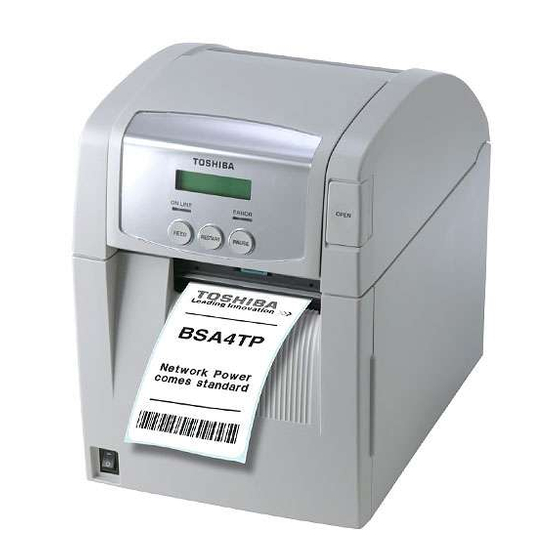
Toshiba B-SA4TM Maintenance Manual
B-sa4t series
Hide thumbs
Also See for B-SA4TM:
- Owner's manual (132 pages) ,
- Option installation manual (58 pages) ,
- Product description (45 pages)
Summary of Contents for Toshiba B-SA4TM
- Page 1 TOSHIBA Thermal Printer B-SA4T SERIES Maintenance Manual Document No. EO18-33016A Original Jul., 2005 (Revised Sep., 2005) PRINTED IN JAPAN...
-
Page 2: Table Of Contents
PERIODIC MAINTENANCE PROCEDURE ---------------------------------------------------------------- 4- 1 TROUBLESHOOTING ------------------------------------------------------------------------------------------- 5- 1 NOTE: Though the pictures used in this document are mostly those of the B-SA4TM (Metal cover model), the replacement procedures are in common with the B-SA4TP (Plastic cover model). [B-SA4TM]... -
Page 3: Unpacking
1. Open the carton. 2. Take out the accessories and the top pad from the carton. 3. Take out the printer from the carton. Accessories Top Pad Carton Printer 4. Remove the tapes from the printer. [B-SA4TM] [B-SA4TP] 1- 1... -
Page 4: Checks
(B-SA4TM only) Supply Loading Instructions Safety Precautions Warranty Disclaimer Sheet Quality Control Report (Doc. No. EO2-33015 for B-SA4TM) (Doc. No.: EO2-33016) (Doc. No. EO2-33017 for B-SA4TP) NOTE: Keep the carton and pads for later transport. 2. PRINTER INSTALLATION 1. Place the printer on the level surface. -
Page 5: Main Unit Replacement
3.MAIN UNIT REPLACEMENT EO18-33016A 3.1 PS Unit 3. MAIN UNIT REPLACEMENT WARNING! Turn the power off and disconnect the power cord before replacing the main parts. 3.1 PS Unit 1. Remove the screw from the back of the printer, and draw out the PS Unit halfway. NOTE: If the PS Unit cannot be drawn out smoothly, check whether it gets stuck with the harnesses on both sides. - Page 6 3.MAIN UNIT REPLACEMENT EO18-33016A 3.1 PS Unit 4. Remove the screw to release the Ground Wire of the Inlet Ass’y. Inlet Ass’y Ground Wire SMW-4x8 Screw 5. Draw out the PS PC Board Unit from the printer. PS PC Board Unit 6.
-
Page 7: Main Pc Board Ass'y
1. Remove the two screws from the back of the printer. SMW-3x6 Screw SMW-3x8* Screw [B-SA4TM] [B-SA4TP] 2. Only for the B-SA4TM model, open the Front Cover, and remove the two screws that secure the Front Cover. Front Cover SMW-3x6 Screw 3. Close the Front Cover. - Page 8 (White) SMW-3x8 Screw Power Cable Connector Lock To easily remove the MAIN PC board from the B-SA4TM model, remove the cable protection cover by squeezing and raising it. Cable Protection Cover Remove the two screws from the printer back. Also, remove the screw which secures the MAIN PC board together with the ground wires (orange and red lead wires).
-
Page 9: Ribbon Motor/Ribbon Sensor
3.MAIN UNIT REPLACEMENT EO18-33016A 3.2 MAIN PC Board Ass’y 11. Replace the MAIN PC board with a new one, and reassemble in the reverse order of removal. CN11 External I/O (Not used) CN13 Print Head, Signal Panel PCB Serial Interface CN19 Parallel I/F Expansion I/O PCB... - Page 10 3.MAIN UNIT REPLACEMENT EO18-33016A 3.2 MAIN PC Board Ass’y NOTES: 1. When re-attaching the Side Panel, be careful not to pinch the lead wires between the printer frames and the Side Panel. Be careful not to pinch the lead wires by the Side Panel.
- Page 11 3.MAIN UNIT REPLACEMENT EO18-33016A 3.3 Platen 3.3 Platen 1. Open the Top Cover. 2. Push both Platen Holders inside to release the hooks, and lift the Platen Ass’y. Platen Holder Platen Holder Platen Ass’y NOTES: 1. Do not disassemble the Platen Ass’y further as a Platen Ass’y is a minimum unit. 2.


