Hoshizaki IM-500SAA Service Manual
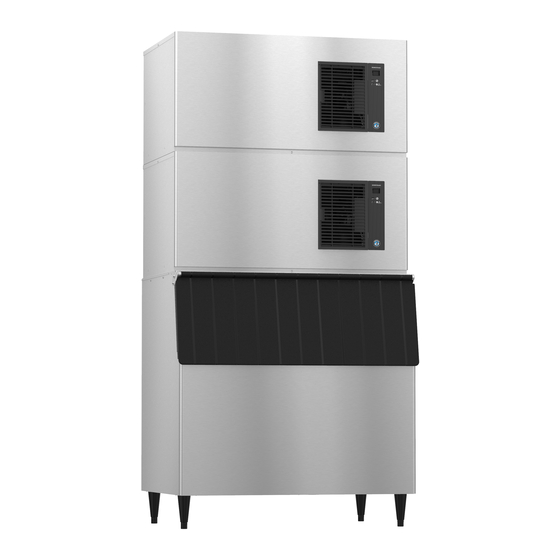
Stackable square cuber
Hide thumbs
Also See for IM-500SAA:
- Service manual (40 pages) ,
- Manual (24 pages) ,
- Instruction manual (22 pages)

Related Manuals for Hoshizaki IM-500SAA


Summary of Contents for Hoshizaki IM-500SAA
- Page 1 Hoshizaki Hoshizaki America, Inc. Stackable Square Cuber Model IM-500SAA SERVICE MANUAL “A Superior Degree of Reliability” www.hoshizaki.com Number: M029-897 Issued: 2-8-2013 Revised: 5-19-2014...
- Page 2 Hoshizaki provides this manual primarily to assist qualified service technicians in the service of the appliance. Should the reader have any questions or concerns which have not been satisfactorily addressed, please call, send an e-mail message, or write to the Hoshizaki Technical Support Department for assistance. Phone: 1-800-233-1940; (770) 487-2331 Fax: 1-800-843-1056;...
-
Page 3: Table Of Contents
IMPORTANT This manual should be read carefully before the appliance is serviced. Read the warnings and guidelines contained in this manual carefully as they provide essential information for the continued safe use, service, and maintenance of the appliance. Retain this manual for any further reference that may be necessary. CONTENTS Important Safety Information .................... -
Page 4: Important Safety Information
Important Safety Information Throughout this manual, notices appear to bring your attention to situations which could result in death, serious injury, damage to the appliance, or damage to property. WARNING Indicates a hazardous situation which could result in death or serious injury. - Page 5 WARNING, continued • The appliance is not intended for use by persons (including children) with reduced physical, sensory, or mental capabilities, or lack of experience and knowledge, unless they have been given supervision or instruction concerning use of the appliance by a person responsible for their safety. •...
-
Page 6: Construction And Water/Refrigeration Circuit Diagram
Thermostatic Expansion Valve Inlet Water Valve Hot Gas Valve High-Pressure Switch Condenser Pump Motor Actuator Motor Fan Motor Drain Pan Control Board Thermistor Drier Control Box Compressor Evaporator Thermistor Fuse Holder Control Switch Water Tank Bin Control Model Shown: IM-500SAA... -
Page 7: Water/Refrigeration Circuit Diagram
B. Water/Refrigeration Circuit Diagram 1. Air-Cooled Model (SAA) Inlet Water Valve Thermostatic Expansion Valve Evaporator Evaporator Thermistor Water Tank Water Pump Condenser Heat Exchanger Hot Gas Fan Motor Valve Strainer Compressor Drier Water Circuit Refrigerant Circuit... -
Page 8: Sequence Of Operation And Service Diagnosis
II. Sequence of Operation and Service Diagnosis A. Sequence of Operation Flow Chart "IM" Control Board 1. 30-Sec. 3. Freeze Cycle 2. Harvest Cycle Cycle Startup • Max. freeze time: 45 min. (CB Setting 6) • HGV: If CBT≤81°F (27°C) (CB Setting Steps Cycle 74), HGV repeatedly energizes 40 sec./... -
Page 9: Sequence Of Operation
B. Sequence of Operation 1. Startup Cycle When power supply is turned on, "on" appears on CB display and HGV energizes. 30 sec. later, harvest cycle starts. • If the "RESET" button is pressed during 30-sec. startup cycle time, startup cycle ends immediately and harvest cycle starts. -
Page 10: Shutdown
ET temperature is recorded 30 seconds after PM energizes. Water temperature correction value (CB Setting 13) is added to ET temperature and this is used as WT value in following harvest cycle. If CBT>81°F (27°C) (CB Setting 74) and CBT≤111°F (44°C) (CB Setting 70), when ET≤-1.3°F (-18.5°C) (CB Setting 2), HGV energizes 5 sec., de-energizes 25 sec., energizes 5 sec. -
Page 11: Service Diagnosis Table
C. Service Diagnosis Table First see "III.G. Error Codes." If there are no recorded errors, refer to the table below. No Ice Production - Possible Cause 1. Power Supply a) Off, blown fuse, or tripped breaker. b) Not within specifications. 2. - Page 12 Low Ice Production - Possible Cause Long Harvest Cycle 1. Evaporator a) Scaled up. 2. Refrigerant Charge a) Low. 3. Control Board a) Thermistor connection loose (K3). b) Defective. 4. Evaporator (Cube Control) a) Loose, disconnected, or defective. Thermistor See "II.E. Evaporator Thermistor Check"...
- Page 13 Large-Hole Cubes - Possible Cause (Also see III.H.1. Dimple Diameter") 4. Icemaker Location a) Insufficient clearance. b) Ambient temperature too high. 5. Water Supply a) Water leaks. b) Improper water pressure. Cloudy Cubes - Possible Cause 1. Water Quality a) High hardness. See "III.H.2. Ice Clarity." 2.
-
Page 14: Bin Control Check And Cleaning
D. Bin Control Check and Cleaning 1. Bin Control Check This appliance uses a lever-actuated proximity switch to control the ice level in the storage bin. No adjustment is required. To check, follow the steps below. 1) Turn off the power supply. 2) Remove the front panel, then move the control switch to the "OFF"... -
Page 15: Bin Control Cleaning
BC from the bin control bracket and move to the front of the icemaker for cleaning. 5) Remove the actuator paddle from the switch mount. See Fig. 1. 6) Wipe down BC with a mixture of 1 part of Hoshizaki "Scale Away" and 25 parts of warm water. Rinse the parts thoroughly with clean water. -
Page 16: Evaporator Thermistor Check
E. Evaporator Thermistor Check To check thermistor resistance, follow the steps below. 1) Turn off the power supply. 2) Remove the front panel. Move the control switch to the "OFF" position. 3) Remove the control box cover. 4) Remove the thermistor from the evaporator. 5) Immerse the thermistor sensor portion in a glass containing ice and water for 2 or 3 min. -
Page 17: Controls And Adjustments
The control switch has three positions: OFF for power off, ICE for icemaking, and WASH to energize the water pump when cleaning and sanitizing. B. Control Board • A Hoshizaki exclusive control board is employed in IM series appliances. • All models are pretested and factory adjusted. NOTICE •... -
Page 18: Control Board Layout
1. Control Board Layout • CN16 Connector Actuator Motor Position Sensor (Hall IC) Input • CN11 Connector Bin Control Input • CN13 Connector Evaporator (Cube Control) Thermistor Input • CN10 Connector • CN9 Connector Compressor Start DC Relay Drive Output Display Output •... -
Page 19: Control Buttons
C. Control Buttons The control board features RESET, SERVICE 1, and SERVICE 2 Buttons 1. RESET Button • Press briefly to go to initial harvest cycle. • Press and hold for 3 seconds to enter control board setting mode. For details about control board settings, see "III.D. -
Page 20: Control Board Settings
D. Control Board Settings NOTICE Failure to maintain factory settings may adversely affect performance and warranty coverage. For more information, contact your Hoshizaki Service Center. 1) With "on" in display, press and hold the "RESET" button for 3 seconds. Display changes to "1". - Page 21 Control Board (CB) Setting Menu IM-500SAA Category No. Item Range Default Water 12 Freeze Cycle Water Supply Time 1: Partial Drain (CB 0 to 90 sec. Supply, Setting 14) (1 sec. increments) continued Freeze Cycle Water Supply Time 1: Full Drain (CB...
- Page 22 Control Board (CB) Setting Menu IM-500SAA Category No. Item Range Default Compressor 37 Compressor Output Selection 0: X8 (DC Relay) On DO NOT ADJUST 1: X1 (AC Relay) On Anti-Slush 50 Pump De-Energized Time 0 to 90 sec. Control When temperature at evaporator (cube control) 0=ignore, no anti-slush thermistor drops to 37°F (3°C) in the freeze cycle,...
-
Page 23: Control Board Information Display
Temperature at evaporator (cube control) (9°C) thermistor 30 seconds after pump motor "L" if 48°F (9°C) or energized in freeze cycle plus the water Lower temperature correction value (Control Board Setting 13). Current Condenser Thermistor Temperature °C Not Applicable to IM-500SAA... - Page 24 Control Board Information Display History Cleared by Pressing and Holding SERVICE 1 and SERVICE 2 Buttons Simultaneously for 5 Sec. when Item Value No. Item Description is Displayed? Last Completed Freeze Cycle Time 0 to 99 min. Freeze cycles interrupted by bin control shutdown or the "RESET"...
-
Page 25: Control Board Model Code Setting
0, 1, 2, 3, 4, 5, 6, 7, 8, 9, A, B, C, D, E, F. When a valid model code is displayed, the dot in the bottom right of the display turns on. For IM-500SAA, set model code to "08". - Page 26 0, 1, 2, 3, 4, 5, 6, 7, 8, 9, A, B, C, D, E, F. When a valid model code is displayed, the dot in the bottom right of the display turns on. For IM-500SAA, set model code to "08".
-
Page 27: Error Codes
G. Error Codes When the control board detects an error, the display shows one of the following error codes in the display mode. Error codes other than E1 and E2 are displayed as "EE" at the time of occurrence. To see the actual error code, see the error log. 1. -
Page 28: Quick Adjustments
Condenser Thermistor Error Replace condenser thermistor. (E9) If condenser thermistor is open or shorted for 2 sec., unit stops. Note: IM-500SAA does not utilize a condenser thermistor, therefore E9 error will not occur. Control Board Error Replace control board. (EA) If model data IC is defective, unit stops. -
Page 29: Ice Clarity
3) Press the "SERVICE 2" button to lower freeze cycle termination temperature setting (Control Board Setting 2). Temperature setting lowers in .5°C increments. The "." in the lower, right corner of the display indicates .5°C. Default is -18.5°C. NOTICE! Do not decrease dimple size below 3/16"... -
Page 30: Refrigeration Circuit And Component Service Information
IV. Refrigeration Circuit and Component Service Information WARNING • This appliance should be diagnosed and repaired only by qualified service personnel to reduce the risk of death, electric shock, serious injury, or fire. • Move the control switch to the "OFF" position and turn off the power supply. Place the disconnect in the "OFF"... - Page 31 2. Brazing WARNING • R-404A itself is not flammable at atmospheric pressure and temperatures up to 176°F (80°C). • R-404A itself is not explosive or poisonous. However, when exposed to high temperatures (open flames), R-404A can be decomposed to form hydrofluoric acid and carbonyl fluoride both of which are hazardous.
-
Page 32: Component Service Information
5) Disconnect the gauge manifold hose from the vacuum pump and attach it to a refrigerant service cylinder. Remember to loosen the connection and purge the air from the hose. For the required refrigerant charge, see the nameplate. Hoshizaki recommends only virgin refrigerant or reclaimed refrigerant which meets ARI Standard 700 (latest edition) be used. - Page 33 Water Pan Refer to illustration for assembly. Assembly 1. Water Tank 2. Water Plate Bracket 3. Bracket 4. Spring Hook Screw 5. Pump Tubing (Suction) 6. Pump Tubing (Discharge) 7. Pump Motor Bracket 8. Water Plate 9. Overflow Pipe 10. Screw (for Overflow Pipe) 11.
-
Page 34: Maintenance
V. Maintenance The maintenance schedule below is a guideline. More frequent maintenance may be required depending on water quality, the appliance's environment, and local sanitation regulations WARNING • Only qualified service technicians should service the appliance. • To reduce the risk of electric shock, do not touch the control switch or service switch with damp hands •... -
Page 35: Preparing The Icemaker For Periods Of Non-Use
VI. Preparing the Icemaker for Periods of Non-Use NOTICE • When storing the appliance for an extended time or in sub-freezing temperatures, follow the instructions below to prevent damage. • To prevent damage to the water pump, do not operate the appliance with the control switch in the "WASH"... -
Page 36: Disposal
VII. Disposal The appliance contains refrigerant and must be disposed of in accordance with applicable national, state, and local codes and regulations. Refrigerant must be recovered by properly certified service personnel. -
Page 37: Technical Information
VIII. Technical Information We reserve the right to make changes in specifications and design without prior notice. A. Specification Data 1. IM-500SAA AC SUPPLY VOLTAGE 115/60/1 11.5 A ( 5 Min. Freeze AT 104°F / WT 80°F) AMPERAGE MINIMUM CIRCUIT AMPACITY... -
Page 38: Performance Data
B. Performance Data Pressure data is recorded at 5 min. into freezing cycle. The data not in bold should be used for reference only. 1. IM-500SAA APPROXIMATE ICE WATER TEMP. (ºF/ºC) AMBIENT TEMP. PRODUCTION PER 24 HR. (ºF/ºC) 50/10 70/21... -
Page 39: Wiring Diagram
C. Wiring Diagram 1. IM-500SAA...