Advertisement
SERVICE MANUAL
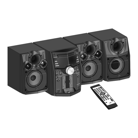
COMPACT COMPONENT SYSTEM
8 S ERVICE MANUAL
2008
MB664<Rev.002>
MX-KC68J, MX-KC68C, MX-KC68B, MX-KC68E,
MX-KC68EN, MX-KC68EV, MX-KC68A,
MX-KC68UJ, MX-KC68UW, MX-KC38J, MX-KC38C
COPYRIGHT © 2008 Victor Company of Japan, Limited
Lead free solder used in the board (material : Sn-Ag-Cu, melting point : 219 Centigrade)
Lead free solder used in the board (material : Sn-Cu, melting point : 230 Centigrade)
1
PRECAUTION. . . . . . . . . . . . . . . . . . . . . . . . . . . . . . . . . . . . . . . . . . . . . . . . . . . . . . . . . . . . . . . . . . . . . . . . . 1-5
2
SPECIFIC SERVICE INSTRUCTIONS . . . . . . . . . . . . . . . . . . . . . . . . . . . . . . . . . . . . . . . . . . . . . . . . . . . . . . 1-8
3
DISASSEMBLY . . . . . . . . . . . . . . . . . . . . . . . . . . . . . . . . . . . . . . . . . . . . . . . . . . . . . . . . . . . . . . . . . . . . . . . 1-8
4
ADJUSTMENT . . . . . . . . . . . . . . . . . . . . . . . . . . . . . . . . . . . . . . . . . . . . . . . . . . . . . . . . . . . . . . . . . . . . . . . 1-20
5
TROUBLESHOOTING . . . . . . . . . . . . . . . . . . . . . . . . . . . . . . . . . . . . . . . . . . . . . . . . . . . . . . . . . . . . . . . . . 1-21
(MX-KC68B,E,EN,EV)
TABLE OF CONTENTS
COPYRIGHT © 2008 Victor Company of Japan, Limited
No.MB664<Rev.002>
2008/8
Advertisement

Related Manuals for JVC MX-KC68J


Summary of Contents for JVC MX-KC68J
-
Page 1: Table Of Contents
SERVICE MANUAL COMPACT COMPONENT SYSTEM MB664<Rev.002> 2008 8 S ERVICE MANUAL MX-KC68J, MX-KC68C, MX-KC68B, MX-KC68E, MX-KC68EN, MX-KC68EV, MX-KC68A, MX-KC68UJ, MX-KC68UW, MX-KC38J, MX-KC38C (MX-KC68B,E,EN,EV) COPYRIGHT © 2008 Victor Company of Japan, Limited Lead free solder used in the board (material : Sn-Ag-Cu, melting point : 219 Centigrade) - Page 2 SPECIFICATION MX-KC68J/C/MX-KC38J/C Amplifier section OUTPUT POWER Main speakers 110 W per channel min. RMS driven into 3Ω at 1 kHz with no more than 10% total harmonic distortion 3Ω - 6 Ω Speakers/Impedance Subwoofer (for MX-KC68) 180 W per channel min. RMS driven into 8 Ω at 63 Hz with no more than 10% total harmonic distortion 8 Ω...
- Page 3 MX-KC68B/E/EN/EV Amplifier section 110 W per channel min. RMS driven into 3 Ω at 1 kHz with no more than 10% total harmonic distortion OUTPUT POWER Main speakers Speakers/Impedance: 3 Ω - 6 Ω 180 W min. RMS driven into 8 Ω at 63 Hz with no more than 10% total harmonic distortion Subwoofer Speakers/Impedance: 8 Ω...
- Page 4 MX-KC68A/UJ/UW Amplifier section 110 W per channel min. RMS driven into 3 Ω at 1 kHz with no more than 10% total harmonic distortion OUTPUT POWER Main speakers Speakers/Impedance: 3 Ω - 6 Ω 180 W per channel min. RMS driven into 8 Ω at 63 Hz with no more than 10% total harmonic distortion Subwoofer Speakers/Impedance: 8 Ω...
-
Page 5: Precaution
SECTION 1 PRECAUTION Safety Precautions (1) This design of this product contains special hardware and voltmeter. many circuits and components specially for safety purpos- Move the resistor connection to each exposed metal es. For continued protection, no changes should be made part, particularly any exposed metal part having a return to the original design unless authorized in writing by the path to the chassis, and measure the AC voltage across... - Page 6 Preventing static electricity Electrostatic discharge (ESD), which occurs when static electricity stored in the body, fabric, etc. is discharged, can destroy the laser diode in the traverse unit (optical pickup). Take care to prevent this when performing repairs. 1.5.1 Grounding to prevent damage by static electricity Static electricity in the work area can destroy the optical pickup (laser diode) in devices such as laser products.
- Page 7 Important for laser products 1.CLASS 1 LASER PRODUCT 5.CAUTION : If safety switches malfunction, the laser is able to function. 2.CAUTION : (For U.S.A.) Visible and/or invisible class II laser radiation 6.CAUTION : Use of controls, adjustments or performance of when open.
-
Page 8: Specific Service Instructions
When it repair the CD mechanism of an article sticking this label on, please use a parts list of FMU-VK1-2M. A label for identification SECTION 3 DISASSEMBLY Main body (Used figure are MX-KC68J) 3.1.1 Removing the Metal cover (See Fig.1, 2) (1) Remove the six screws A attaching the Metal cover. (See Fig.1) (2) Remove the four screws B attaching the both side of the Metal cover. - Page 9 3.1.2 Removing the Tuner pack (See Fig.3, 4) (1) Disconnect the card wire from Tuner pack connected to connector CN707 of the Micom board. (See Fig.3) (2) Remove the two screws C attaching the Tuner pack. (See Fig.4) CN707 Fig.3 Fig.4 3.1.3 Removing the CD mechanism (See Fig.5, 6) (1) Disconnect the card wire from CD mechanism connected...
- Page 10 3.1.4 Removing the CD chassis (See Fig.7, 8) (1) Remove the two screws E attaching the both side of the Front panel. (See Fig.7) (2) Remove the two screws F attaching the CD chassis. (See Fig.8) Fig.7 Fig.8 3.1.5 Removing the Front panel (See Fig.9 to 11) (1) Disconnect he card wire from FL board connected to con- nector CN700...
- Page 11 3.1.6 Removing the Rear panel (See Fig.12, 13) CN706 (1) Disconnect the connector wire from Fan connected to con- nector CN706 of the Micom board. (See Fig.12) (2) Remove the four screws H attaching the Rear panel. (See Fig.13) Fig.12 Fig.13 3.1.7 Removing the Micom board (See Fig.14, 15) (1) Remove the one screw J attaching the Micom board.
- Page 12 3.1.8 Removing the Power supply unit (See Fig.16) (1) Disconnect the Power cord connected to connector the Power supply unit. (2) Disconnect the connector wire from Power amp board con- nected to connector of the Power supply unit. (3) Remove the six screws K attaching the Power supply unit. 3.1.9 Removing the Power amp board (See Fig.16) (1) Remove the four screws L attaching the Power amp board.
- Page 13 3.1.11 Removing the Volume board (See Fig.18) (1) Remove the volume knob. (2) Disconnect the flat cable wire connected to connector CN951 of the Headphone jack board. (3) Remove the seven screws N attaching the Volume board. CN951 Fig.18 3.1.12 Removing the Audio input board (See Fig.19) (1) Remove the two screws P attaching the Audio input board.
- Page 14 CD mechanism assembly • Remove the CD mechanism assembly from main body. 3.2.1 Removing the CD cover (See Fig.1) (1) Remove the two screws A attaching the CD cover from bot- tom side of CD mechanism assembly. Boss a Fixing part b (2) Lift up the CD cover from disengage boss a of the CD mechanism assembly.
- Page 15 3.2.3 Removing the traverse mechanism assembly (See Fig.4) (1) Remove the four screws C attaching the traverse mecha- CD mechanism assembly nism assembly from bottom side of CD mechanism assem- bly. CD servo board Card wire (2) Disconnect the card wire from connector CN602 of the CD servo board and then take out the traverse mechanism as-...
- Page 16 3.2.4 Removing the CD servo board (See Fig.5 and 6) • Remove the traverse mechanism assembly. Solder part e Yellow wire (1) Remove the two screws D attaching the CD servo board from bottom side of traverse mechanism assembly. (See Fig.5) (2) Remove the solder from solder part e of the CD servo White wire...
- Page 17 3.2.5 Removing the pickup (See Fig.7 to 9) • Remove the traverse mechanism assembly. (1) Remove the one screw E attaching the plate from upper Feed gear Shaft LEAD spring side of traverse mechanism assembly. (See Fig.7) (2) Remove the plate from fixing part k then take out the plate. (See Fig.7) Part m (3) Remove the two screws F attaching the LEAD spring and...
- Page 18 3.2.7 Removing the feed motor (See Fig.11 to 13) • Remove the traverse mechanism. Feed gear Feed motor part t (1) Remove the yellow wire from solder part q of the CD servo board from upper side of traverse mechanism. (See Fig.11) (2) Remove the white wire from solder part r of the CD servo board.
- Page 19 3.2.8 Removing the switch board (See Fig.14) (1) Disconnect the card wire from of the switch board Hook v Switch board Wire from bottom side of CD mechanism assembly. (2) Remove the wire from solder part u of the switch board. Solder (3) Remove the one screw H attaching the switch board to CD part u...
-
Page 20: Adjustment
SECTION 4 ADJUSTMENT Outline CD TEST MODE C1 error display How to go CD TEST MODE [SET] + [POWER] + AC in Function specification Function Operation FL display CD TEST MODE C1 error display Remocon C1 error display Remocon After receive data Return to CD TEST MODE CANCEL Remocon... -
Page 21: Troubleshooting
SECTION 5 TROUBLESHOOTING This service manual does not describe TROUBLESHOOTING. (No.MB664<Rev.002>)1-21... - Page 22 Victor Company of Japan, Limited Audio/Video Systems category 10-1,1chome,Ohwatari-machi,Maebashi-city,371-8543,Japan (No.MB664<Rev.002>) Printed in Japan...