JVC MX-KC4 Instructions Manual
Compact component system
Hide thumbs
Also See for MX-KC4:
- Service manual (61 pages) ,
- Instructions manual (29 pages) ,
- Instructions manual (88 pages)
Table of Contents
Advertisement
Quick Links
JVC
COMPACT COMPONENT
SYSTEM
MX-KC4
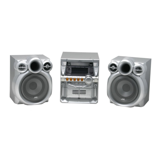
Consists
of CA-MXKC4
and SP-MXKC4
SP-MXKC4
CA-MXKC4
SP-MXKC4
DIGITAL AUDIO
INSTRUCTIONS
For Customer
Use:
Enter below the Model No. and Serial No.
which are located either on the rear, bot-
tom or side of the cabinet.
Retain
this
information
for future reference.
Model No.
Serial No.
LVT1343-001 B
[d]
Advertisement
Table of Contents

Related Manuals for JVC MX-KC4


Summary of Contents for JVC MX-KC4
- Page 1 COMPACT COMPONENT SYSTEM MX-KC4 Consists of CA-MXKC4 and SP-MXKC4 SP-MXKC4 CA-MXKC4 SP-MXKC4 DIGITAL AUDIO INSTRUCTIONS For Customer Use: Enter below the Model No. and Serial No. which are located either on the rear, bot- tom or side of the cabinet. Retain this information...
- Page 2 Warnings, Cautions and Others CAUTION: TO REDUCE RISK OF ELECTRIC SHOCK DO NOT REMOVE COVER (OR BACK) NO USER SERVICEABLE PARTS INSIDE REFER SERVICING TO QUALIFIED SERVICE PERSONNEL. The lightning flash with arrowhead symbol, within an equilateral triangle is intended to alert the user to the presence of uninsulated "dangerous voltage"...
- Page 3 CLASS 1 LASER PRODUCT DANGER 1. Invisible laser radiation when open and interlock failed or defeated. Avoid direct exposure to beam. CAUTION 1. Do net open the top cover. There are no user serviceable parts inside the unit; leave all servicing to qualified service personnel.
-
Page 4: Introduction
Thank you for purchasing the JVC Compact Component System. We hope it will be a valued addition to your home, giving you years of enjoyment. Be sure to read this instruction manual carefully before operating your new stereo system. In it you will find all the information you need to set up and use the system. -
Page 5: Table Of Contents
Introduction ........................Features ..............................How This Manual Is Organized ....................... IMPORTANT CAUTIONS ........................Table of Contents ......................Getting Started ......................Accessories .............................. How To Put Batteries In the Remote Control ..................Using the Remote Control ........................Connecting the FM Antenna ........................Connecting the AM Antenna ........................ -
Page 6: Accessories
Accessories Make sure that you have all of the following items, which are supplied with the System. AM Loop Antenna FM Wire Antenna Remote Control Batteries If any of these items are missing, contact your dealer immediately. To Put Batteries In the Remote Control Match the polarity... -
Page 7: Connecting The Fm Antenna
Getting Started _CAUTION: • Make all connections before plugging the System into an AC power outlet. Connecting the FM Antenna Using the Supplied Wire Antenna FM wire antenna (supplied) BBBB BBBBBDDDDDDt Extend the supplied FM Wire Antenna horizontally. BBBBBBBBBBDDDDDDI BBBBB _ DDDDDi_I BBBBB DDDDD/;_;i... -
Page 8: Connecting The Am Antenna
Getting Started Connecting the AM Antenna Rear Panel of the Unit Turnthe loop until you have the best reception. AM loop antenna (Supplied Attach the AM loop to its base by snapping the tabs on the loop into the slot in the base. •... -
Page 9: Connecting External Equipment
Play JVC's COMPU PLAY feature lets you control the most frequently used System functions with a single touch. With One Touch Operation you can play a CD, a tape, turn on the radio, or listen to an external equipment with a single press of the play button for that function. -
Page 10: Basic Operations
o oo 1 STANDBY/ON d)/I Display RHYTHM AX Numeric keys SOUND MODE VOLUME _/I STANDBY/ON STANDBY indicatol SOUND MODE VOLUME +, FADE MUTING Various information I ..... RHYTHM I--I I I',;I I I-- Sound Mode indicator I_._L__I I I I-" !!!!!!!i!!i !!!!!!!!!!i iini... -
Page 11: Enjoying The Powerful Sound (Rhythm Ax)
Basic Operations Entering Number with Fade.out Muting (FADE MUTING) Remote Control (Numeric Keys) You can mute the output with one touch operation. You will use the number keys on the Remote Control to enter num- To muting output, press the FADE MUTING button on the bers for presetting... -
Page 12: Tuning In A Station
® ®I@ ® ® @/o Numeric -- keys FM/AM FM/AM FM MODE ©<D _E_TEeONmOL Band display, Frequency display, Preset channel I-_ I',tl I t?1_t I LI_t._I FM mode indicators * When the System is in use, the display shows other items as well. For simplicity, we show here only the items described in this section. -
Page 13: Using The Tuner
Using the Tuner _CAUTION: • Even if the System is unplugged or if the power • tn AM broadcast, reception sensitivity will be changed by failure occurs, the preset stations will be stored turning the AM loop antenna. Turn the AM loop antenna for best reception. - Page 14 REPEAT PROGRAM RANDOM pen/ Close _A CD I,>/II Numeric keys CANCEL CD1-CD3 IIIII CD1-CD3 --CD I,>/II REPEAT -- PROGRAM Track number, Playing time, _UND V_UME /RANDOM Program number, etc. Program indicator MP3 indicator s Disc indicators .IVC --'U" 'E -T-3 _ N REMOTE CONTROL Random Repeat...
-
Page 15: Using The Cd Player
Using the CD Player About Disc Indicator: [71 When you use an 8 cm (3") CD, place it on the inner circle of the tray. Disc Rotation [71 You can load CDs while listening to the other source or while indicator listening to the CD being played back. -
Page 16: Basics Of Using The Cd Player-Normal Play
Using the CD Player GROUP mode Basics of Using the CD Player..i';_/ Normal Play i F'7t __ t .-3 L-7 L_) : :_ Total track number To Play CDs Total group number To pause, press the CD )-/11 button. The playing time indication Load CDs. -
Page 17: Programming The Playing Order Of The Tracks
Using the CD Player Using the Remote Control Programming the Playing Order Press the numeric keys to directly enter the track number. Then, the program order number will be assigned from P-I. of the Tracks • To delete the current program step, press the CANCEL button... -
Page 18: Random Play
Using the CD Player Tray Lock Function Random Play The tracks of the selected CD will play in no special order when In order to safely keep the CD in the CD Player, the tray can be you use this mode. electronically locked. -
Page 19: Using The Cassette Deck (Listening To A Tape)
® ® ®IQ TAPE A ® ® TAPE B • PUSH OPEN A PUSH OPEN (Deck B) (Deck A) TAPE B P,- TAPE A REMOTE CONTROL Tnnr t I II Deck indicators _: Tape indicator * When the System is in use, the disp/ay shows other items as we//. For simplicity, we show here only the items described in this section. -
Page 20: Using The Cassette Deck (Recording)
CD RED START -- PROGRAM TAPE B TAPE A A PUSH OPEN A PUSH OPEN (Deck B) (Deck "_ nEWEST P_A.a_M TAPE A TAPE B TNNr I III I'_1 _: Tape indicator Deck indicators RED indicator * When the System is in use. the display shows other items as well. For simplicity, we show here only the items described in this section. -
Page 21: Standard Recording
Using the Cassette Deck (Recording) Insert a blank or erasable tape into the Deck Standard Recording B and wind past the tape leader. 3 Press the CD REC START button on the Unit. This is the basic method for recording any source. -
Page 22: Using An External Equipment
® ®I@ ® Q ®I_ -- AUX i _ _ EEED _ AUX jack C_T_ ° nE.OTE CONTROL Listening to the External Equipment You can listen to the external equipment such as portable CD, MD player, STB, or other auxiliary. First, make sure that the external equipment is properly... -
Page 23: Using The Timers
® ® SLEEP CLOCK/TIMER DAILY Timer indicator SLEEP indicator T T I_1 I_ I_ REC (Recording) Timer indicator J ± I _ L Timer indicator * When the System is in use, the display shows other items as well. For simplicity, we show here only the items described in this section. -
Page 24: Setting The Daily Timer
Using the Timers 2. Press the _ or _ button to set the minute, then press the Setting the Daily Timer SET button. Once you have set the Daily Timer, the timer will be activated --_ A 1 L'i--_"l the same time every clay. // * ;I-I__ I_ 11 1 I"71. -
Page 25: Setting The Rec (Recording) Timer
Using the Timers Preparation for each music source: Turning the DailyTimer On and Off Perform the following operation according to the music source Once you have set tile Daily Timer, it is stored in memory. So, tile you have selected. Then, the System enters Volume Setting Daily Timer will be activated at the same time every day until it is mode. - Page 26 Using the Timers 8 Press the 0/I STANDBY/ON button to turn Using the Unit You can set the time in the same way as I_r setting the Daily Tim- off the System, if necessary. The Timer indicator (tlIP) and "REC" indicator are lit on the 1[ Insert a blank or erasable tape into the Deck...
-
Page 27: Setting The Sleep Timer
Using the Timers Setting the SLEEP Timer Timer Priority Use the Sleep Timer to turn the System off after a certain number Since REC Timer and DAILY Timer can be set independently, of minutes when it is playing. By setting the Sleep Timer, you can may wonder what happens... -
Page 28: Care And Maintenance
Moisture Condensation Handle your CDs and tapes carefully, and they will last a long time. Moisture may condense on the lens inside the System in the Compact Discs following cases: • After tnming on heating in the room. • Only bearing these marks... -
Page 29: Troubleshooting
• If you are having a proNem with your System, check this list for a possible solution before calling for service. • If you cannot solve the problem from the hints given here, or the System has been physically damaged, call a qualified person, such as... - Page 30 WE WANT TO HELP YOU ACHIEVE A PERFECT EXPERIENCE. NEED HELP ON HOW TO HOOK UP? NEED ASSISTANCE ON HOW TO OPERATE? NEED TO LOCATE A JVC SERVICE CENTER? LiKE TO PURCHASE ACCESSORIES? ® E TO HELP! TOLL FREE: 1(800)252-5722 http://www.jvc.com...
- Page 31 OF PUERTO RICO. , WHAT WE WILL DO: If this product is found to be defective within the warranty period, JVC will repair or replace defective parts with new or ,_ rebuilt equivalents at no charge to the original owner.
- Page 32 Amplifier Output Power 180 W per channel, rain. RMS, driven into 6 _Q at lkHz, with no more than 10% total harmonic distortion Input Sensitivity/Impedance (1 kHz) AUX IN 400 mV/50 6- 16f2 Speaker terminals Phones 32 f)- 1 kf_ 15 mW/ch output into 32 f2 Cassette Deck Section...
- Page 33 EN, FR 1204NYMCREBET © 2005 Victor Company of Japan, Limited...