Table of Contents

Related Manuals for Omega OS-MINI SERIES


Summary of Contents for Omega OS-MINI SERIES
- Page 1 ® User’s Guide Shop online at omega.com ® e-mail: info@omega.com For latest product manuals: omegamanual.info MADE IN UNITED KINGDOM OS-MINI SERIES Miniature Non-Contact Infrared Temperature Sensors With Separate Electronics Modules...
- Page 2 For Other Locations Visit omega.com/worldwide The information contained in this document is believed to be correct, but OMEGA accepts no liability for any errors it contains, and reserves the right to alter specifications without notice. WARNING: These products are not designed for use in, and should not be used for, human applications.
-
Page 3: Specification
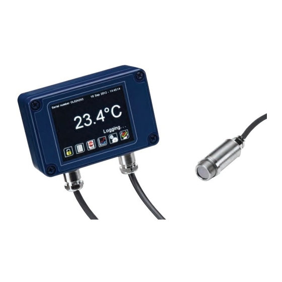
The OS-Mini Series is a range of miniature non-contact infrared temperature sensors with separate electronics modules. All models have an adjustable emissivity setting and are capable of measuring a wide variety of target materials, including food, paper, textiles, plastics, leather, tobacco, pharmaceuticals, chemicals, rubber, coal and asphalt. -
Page 4: Model Numbers
ENVIRONMENTAL Sensing Head Electronics Module Electronics Module (without touch (with touch screen) screen) Environmental Rating IP65 (NEMA 4) IP65 (NEMA 4) – Ambient Temperature See table of Model 0°C to 60°C 0°C to 60°C Range Numbers Relative Humidity Maximum 95% Maximum 95% Maximum 95% non-condensing... -
Page 5: Field Of View
SENSING HEAD OPERATING TEMPERATURE RANGE 0°C to 60°C 0°C to 180°C The high ambient temperature sensing head on -HA models is capable of withstanding temperatures of up to 180°C without cooling. It is available with 20:1 optics. There is no need to supply cooling air or water, and the miniature sensing head is much smaller than bulky, cooled sensors. -
Page 6: Touchscreen Specifications
EXAMPLE: OS-MINI 302-CT-C4-R-D Series Sensing Head Optics Temperature Output and Operating Range Interface Temperature OS-MINI -MA 0°C to 60°C -302 30:1 C4-R-D RS485 divergent within the limits: Modbus output and two -20 to 1000 °C alarm relay outputs, with touch screen EMISSIVITY ADJUSTMENT (-CB MODELS) The emissivity setting on OS-MINI with MA output models may be adjusted via two rotary switches inside the electronics box. -
Page 7: User Interface
USER INTERFACE Default View Temperature View Displays a large indication of the measured temperature. The background turns bright red when an alarm is activated. Setting Press “°C” to switch to °F and vice versa. The units are changed throughout Temperature the interface. - Page 8 Lock/Unlock Prevents settings being changed via a four-digit numerical code. Change Password Enter, confirm and save a new four-digit code. Start/Stop Logging Manually begins or ends data logging (requires MicroSD Card, available separately). If Scheduled Start is enabled in Settings > Data Logging, then logging cannot be started manually.
- Page 9 SETTINGS Date & Time Change the date and time for data logging purposes. The clock is reset when the power is cycled unless a battery is fitted. Output Processing Averaging Set the time, in seconds, over which the measured temperature is averaged. Period Note: averaging prevents the sensor from following rapid temperature changes.
- Page 10 SETTINGS (continued) Emissivity and Compensation Emissivity Enter the emissivity of the target. Target emissivity can be determined Setting experimentally, or estimated using an emissivity table. For more information, contact Calex. Minimum: 0.2. Maximum: 1.0. Enable colder objects. Energy Compensation Temperature Compensation.
- Page 11 SETTINGS > ALARMS Alarm 1 and Alarm 2 Alarm Set The temperature at which the alarm is triggered. Minimum: -20°C. Maximum: Point 1000°C. Hysteresis The temperature difference between the Alarm Set Point and the reset temperature. Hysteresis is only used when Automatic Reset is enabled. Please see the diagrams below for more information Minimum: 0°C (hysteresis disabled).
- Page 12 ALARM OPERATION WITH HYSTERESIS & AUTOMATIC RESET Low Alarm with Automatic Reset High Alarm with Automatic Reset Temperature Temperature Alarm Set Point Hysteresis Hysteresis Alarm Set Point Time Time Alarm triggered Alarm reset Alarm triggered Alarm reset DATA LOGGING (MA-R-D and C4-R-D MODELS) The OS-Mini can be used as a standalone data logger.
-
Page 13: Data Log Files
INSTALLATION OF MICROSD CARD AND BATTERY MicroSD Card Battery (use 1 x BR 1225 3V) DATA LOG FILES Data is saved to the MicroSD Card in .csv format. This file format can be opened or imported by spreadsheet software such as Microsoft Excel. A new folder is created on the MicroSD Card for each day that data is logged. - Page 14 A range of accessories to suit different applications and industrial environments is available. These may be ordered at any time and added on-site. The following accessories are available from Omega: Fixed mounting bracket (see above for dimensions): Allows rotational adjustment in one dimension.
-
Page 15: Installation
INSTALLATION The installation process consists of the following stages: Preparation Mechanical installation Electrical installation Please read the following sections thoroughly before proceeding with the installation. PREPARATION Ensure that the sensor is positioned so that it is focused on the target only. Sensor Target greater BEST... -
Page 16: Power Supply
To minimise electromagnetic interference or ‘noise’, the sensor should be mounted away from motors, generators and such like. POWER SUPPLY Be sure to use a 24 V DC (100 mA) power supply. MECHANICAL INSTALLATION All sensors come with a 1 m cable and a mounting nut as standard. Longer cables are available to order. - Page 17 WIRING (ALL MODELS) Check the distance between the sensing head and the electronics module, and between the electronics module and the instrumentation. If necessary, the sensor can be ordered with a longer cable between the sensing head and the electronics module. The output cable from the electronics module should have an outer diameter between 3.0 and 6.5 mm, with conductors of size 28 to 18 AWG.
- Page 18 Address Length Description R/W/MW (words) 0x06 Unfiltered object temperature 0x08 Sensor temperature 0x0A Maximum temperature over hold period 0x0C Minimum temperature over hold period 0x0E Average temperature over hold period 0x10 Filtered object temperature 0x12 PCB temperature 0x14 Emissivity (1 LSB = 0.0001) Minimum 0.2000, Maximum 1.0000 0x16 Reflected temperature...
-
Page 19: Operation
8-14 microns. The emissivity setting of the sensor should be adjusted to compensate for the presence of the window. Please contact Omega for more information on using the OS-Mini with a window. -
Page 20: Maintenance
In many cases, problems can be solved over the telephone. If the sensor is not performing as it should, try to match the symptom below to the problem. If the table does not help, call Omega for further advice. Troubleshooting... - Page 21 Customer Service Department will issue an Authorized Return (AR) number immediately upon phone or written request. Upon examination by OMEGA, if the unit is found to be defective, it will be repaired or replaced at no charge. OMEGA’s WARRANTY does not...
-
Page 22: Data Acquisition
Where Do I Find Everything I Need for Process Measurement and Control? OMEGA…Of Course! Shop online at omega.com TEMPERATURE M U Thermocouple, RTD & Thermistor Probes, Connectors, Panels & Assemblies M U Wire: Thermocouple, RTD & Thermistor M U Calibrators & Ice Point References M U Recorders, Controllers &...