
Related Manuals for Toshiba RAV-SM1103AT-E1


Summary of Contents for Toshiba RAV-SM1103AT-E1
-
Page 1: Service Manual
FILE NO. A11-016 SERVICE MANUAL (SPLIT TYPE) OUTDOOR UNIT < DIGITAL INVERTER> RAV-SM1103AT-E1 RAV-SM1403AT-E1 R410A PRINTED IN JAPAN, Jan., 2012 ToMo... -
Page 2: Table Of Contents
CONTENTS Precaution for Safety ......................6 New Refrigerant (R410A) ....................11 1. SPECIFICATIONS ......................13 1-1. Outdoor Unit ..........................13 1-2. Characteristic Curve ......................... 14 2. CONSTRUCTION VIEWS (EXTERNAL VIEWS) ............15 3. REFRIGERATING CYCLE DIAGRAM ................. 17 4. WIRING DIAGRAM ...................... 19 5. -
Page 3: Original Instruction
Toshiba Carrier Corporation or, alternatively, he or she has been instructed in such matters by an individual or individuals who have been trained and is thus thoroughly acquainted with the knowledge related to this work. - Page 4 Definition of Protective Gear When the air conditioner is to be transported, installed, maintained, repaired or removed, wear protective gloves and ‘safety’ work clothing. In addition to such normal protective gear, wear the protective gear described below when undertaking the special work detailed in the table below.
-
Page 5: Warning Indications On The Air Conditioner Unit
Warning Indications on the Air Conditioner Unit [Confirmation of warning label on the main unit] Confirm that labels are indicated on the specified positions If removing the label during parts replace, stick it as the original. Warning indication Description WARNING WARNING ELECTRICAL SHOCK HAZARD ELECTRICAL SHOCK HAZARD... -
Page 6: Precaution For Safety
Precaution for Safety The manufacturer shall not assume any liability for the damage caused by not observing the description of this manual. DANGER Before carrying out the installation, maintenance, repair or removal work, be sure to set the circuit breaker to the OFF position. Otherwise, electric shocks may result. Before opening the intake grille of the indoor unit or service panel of the outdoor unit, set the circuit breaker to the OFF position. - Page 7 WARNING The appliance shall be installed in accordance with national wiring regulations. Capacity shortages of the power circuit or an incomplete installation may cause an electric shock or fire. Only a qualified installer (*1) or qualified service person (*1) is allowed to undertake work at heights using a stand of 50 cm or more or to remove the intake grille of the indoor unit to undertake work.
- Page 8 The refrigerant used by this air conditioner is the R410A. Check the used refrigerant name and use tools and materials of the parts which match with it. For the products which use R410A refrigerant, the refrigerant name is indicated at a position on the outdoor unit where is easy to see.
- Page 9 Once the repair work has been completed, check for refrigerant leaks, and check the insulation resistance and water drainage. Then perform a trial run to check that the air conditioner is running properly. After repair work has finished, check there is no trouble. If check is not executed, a fire, electric shock or injury may be caused.
-
Page 10: Declaration Of Conformity
Toshiba Carrier Corporation 336 Tadehara, Fuji-shi, Shizuoka-ken 416-8521 JAPAN Authorized Nick Ball Representative/TCF holder: Toshiba EMEA Engineering Director Toshiba Carrier UK Ltd. Porsham Close, Belliver Industrial Estate, PLYMOUTH, Devon, PL6 7DB. United Kingdom Hereby declares that the machinery described below:... -
Page 11: New Refrigerant (R410A)
New Refrigerant (R410A) This air conditioner adopts a new HFC type refrigerant (R410A) which does not deplete the ozone layer. 1. Safety Caution Concerned to New Refrigerant The pressure of R410A is high 1.6 times of that of the former refrigerant (R22). Accompanied with change of refrigerant, the refrigerating oil has been also changed. - Page 12 4. Tools 1. Required Tools for R410A Mixing of different types of oil may cause a trouble such as generation of sludge, clogging of capillary, etc. Accordingly, the tools to be used are classified into the following three types. 1) Tools exclusive for R410A (Those which cannot be used for conventional refrigerant (R22)) 2) Tools exclusive for R410A, but can be also used for conventional refrigerant (R22) 3) Tools commonly used for R410A and for conventional refrigerant (R22) The table below shows the tools exclusive for R410A and their interchangeability.
-
Page 13: Specifications
1. SPECIFICATIONS 1-1. Outdoor Unit <Digital Inverter> Model name Outdoor unit RAV- SM1103AT-E1 SM1403AT-E1 1 phase 230V (220 – 240V) 50Hz Power supply (Power exclusive to outdoor is required.) Type Hermetic compressor Compressor Motor (kW) Pole Refrigerant charged (kg) Refrigerant control Pulse motor valve Standard length Min. -
Page 14: Characteristic Curve
1-2. Operation Characteristic Curve • Operation Characteristic Curve <Digital Inverter> RAV-SM1103AT-E1,RAV-SM1403AT-E1 <Cooling> <Heating> RAV-SM1103AT-E RAV-SM1103AT-E1 RAV-SM1403AT-E1 RAV-SM1403AT-E RAV-SM1403AT-E RAV-SM1403AT-E1 RAV-SM1103AT-E RAV-SM1103AT-E1 • Conditions • Conditions Indoor : DB27˚C/WB19˚C Indoor : DB20˚C Outdoor : DB35˚C Outdoor : DB7˚C/WB6˚C Air flow : High Air flow : High Pipe length : 7.5m... -
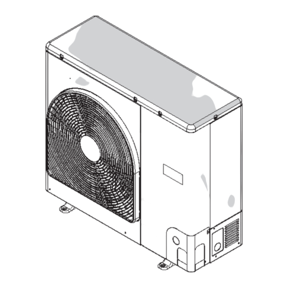
Page 15: Construction Views (External Views)
2 . CONSTRUCTION VIEWS (EXTERNAL VIEWS) RAV-SM1103AT-E1, RAV-SM1403AT-E1 Knockout Drain hole (Ø20 × 88 Burring hole) (For draining) Drain hole (Ø25 Burring hole) Installation bolt hole (Ø12 × 17 U-shape holes) Suction Part B port Suction Details of B part... - Page 16 RBC-TWP30E2, RBC-TWP50E2 (Simultaneous Twin) Inner diameter Ø C Inner Inner diameter Ø D diameter Ø D Model (RBC-) Liquid side Ø9.5 Ø6.4 TWP30E2 Gas side Ø15.9 Ø12.7 Liquid side Ø9.5 Ø9.5 TWP50E2 Gas side Ø15.9 Ø15.9 – 16 –...
-
Page 17: Refrigerating Cycle Diagram
3 . REFRIGERATING CYCLE DIAGRAM RAV-SM1103AT-E1, RAV-SM1403AT-E1 Outer diameter of refrigerant pipe Gas side ØA Liquid side ØB 15.9mm 9.5mm Indoor unit Height difference (m) Distributor TCJ sensor Outdoor unit Outdoor unit (Strainer incorporated) at upper side at lower side... - Page 18 RAV-SM1103AT-E1 Pressure Pipe surface temp. Temp (MPa) (kg/cm C omp. 27/19 3.44 0.92 35.1 HIGH 35/– Standard 3.73 1.18 38.1 12.0 HIGH 32/24 43/– Cooling Overload 1.49 0.70 15.2 LOW 18/15.5 –5/– Low load 0.61 28.6 HIGH 20/– Standard 2.80 3.43...
-
Page 19: Wiring Diagram
4. WIRING DIAGRAM – 19 –... -
Page 20: Specifications Of Electrical Parts
5. SPECIFICATIONS OF ELECTRIC PARTS Part name Type Specifications Compressor DA422A3F-12M Outdoor fan motor WDF-340-A100-1 Output 100W Reactor CH62-2Z-T 6mH, 18.5A 4-way valve coil STF-H01AJ1949A1 AC230V High-pressure SW ACB-4UB83W OFF: 4.15MPa PMV coil UKV-A039 DC12V P.C. board MCC-1630 1Ø AC220V/230V/240V±10%, 50/60HZ Fuse GDT 250V25A AC250V, 25A... -
Page 21: Refrigerant R410A
6. REFRIGERANT R410A This air conditioner adopts the new refrigerant HFC 6. When an air conditioning system charged with a (R410A) which does not damage the ozone layer. large volume of refrigerant is installed in a small room, it is necessary to exercise care so that, The working pressure of the new refrigerant R410A even when refrigerant leaks, its concentration is 1.6 times higher than conventional refrigerant... - Page 22 Table 6-2-1 Thicknesses of annealed copper pipes Thickness (mm) Nominal diameter Outer diameter (mm) R410A 0.80 0.80 0.80 0.80 12.7 0.80 0.80 15.9 1.00 1.00 1. Joints For copper pipes, flare joints or socket joints are used. Prior to use, be sure to remove all contaminants. a) Flare Joints Flare joints used to connect the copper pipes cannot be used for pipings whose outer diameter exceeds 20 mm.
- Page 23 c) Insertion of Flare Nut d) Flare Processing Make certain that a clamp bar and copper pipe have been cleaned. By means of the clamp bar, perform the flare processing correctly. Use either a flare tool for R410A or conventional flare tool. ØD Flare processing dimensions differ according to the type of flare tool.
- Page 24 Fig. 6-2-2 Relations between flare nut and flare seal surface 2. Flare Connecting Procedures and Precautions a) Make sure that the flare and union portions do not have any scar or dust, etc. b) Correctly align the processed flare surface with the union axis. c) Tighten the flare with designated torque by means of a torque wrench.
-
Page 25: Tools
6-3. Tools 6-3-1. Required Tools Refer to the “4. Tools” 6-4. Recharging of Refrigerant When it is necessary to recharge refrigerant, charge the specified amount of new refrigerant according to the following steps. Recover the refrigerant, and check no refrigerant remains in the equipment. -
Page 26: Brazing Of Pipes
1) Be sure to make setting so that liquid can be charged. 2) When using a cylinder equipped with a siphon, liquid can be charged without turning it upside down. It is necessary for charging refrigerant under condition of liquid because R410A is mixed type of refrigerant. Accordingly, when charging refrigerant from the refrigerant cylinder to the equipment, charge it turning the cylinder upside down if cylinder is not equipped with siphon. - Page 27 2. Characteristics required for flux 6-5-3. Brazing • Activated temperature of flux coincides with As brazing work requires sophisticated techniques, the brazing temperature. experiences based upon a theoretical knowledge, it must be performed by a person qualified. • Due to a wide effective temperature range, flux is hard to carbonize.
-
Page 28: Instructions For Re-Use Piping Of R22 Or R407C
Operation System age of the pipe at the worst. • In the concurrent twin system, when TOSHIBA- specified branching pipe is used, it can be reused. ∗ Pipe diameter and thickness (mm) -
Page 29: Final Installation Checks
6-6-5. Final Installation Checks Is there no scratch or dent on the existing pipes? Existing pipe: NO * Use a new pipes. Is it possible to operate the existing air conditioner? ∗ After the existing air conditioner operated in cooling mode for approx. - Page 30 6-6-6. Handling of Existing Pipe When using the existing pipe, carefully check it for the following: • Wall thickness (within the specified range) • Scratches and dents • Water, oil, dirt, or dust in the pipe • Flare looseness and leakage from welds •...
-
Page 31: Circuit Configuration And Control Specifications
7.CIRCUIT CONFIGURATION AND CONTROL SPECIFICATIONS 7-1. Outdoor unit control 7-1-1. Prim circuit board (MCC-1630) – 31 –... -
Page 32: Outline Of Main Controls
7-1-2. Outline of Main Controls 1. Pulse Modulating Valve (PMV) control 1) For PMV with 50 to 500 pulses during operation, respectively. 2) In cooling operation, PMV is controlled with the temperature difference between TS sensor and TC sensor. 3) In heating operation, PMV is controlled with the temperature difference between TS sensor and TE sensor. - Page 33 3. Current release control The output frequency and the output voltage are controlled by AC current value detected by T20 on the outdoor P.C. board so that input current of the inverter does not exceed the specified value. Current [A] Frequency down SM110 SM140...
- Page 34 4-2. Heating fan control 1) An outdoor fan is controlled by TE sensor, TO sensor and operation frequency. (It is controlled with W1 for minimum and the maximum is controlled according to the following table.) 2) At the start time, the fan is fixed for 3 minutes only with the maximum fan tap corresponded to the zone in the following table but it is controlled with TE sensor temperature after then.
- Page 35 6. Short intermittent operation preventive control 1) For 3 to 10 minutes after operation start, in some cases, the compressor does not stop to protect the compressor even if receiving the thermostat-OFF signal from indoor. However it is not abnormal status. (The operation continuance differs according to the operation status.) 2) When the operation stops by the remote controller, the operation does not continue.
- Page 36 Start of heating operation [min.] TE [ ˚ – 5 A zone A zone – 10 – 13 B zone B zone – 18 D zone D zone C zone C zone * From 10 minutes to 15 minutes after a heating operation started, the minimum value of TE is stored in memory as TEO and the minimum temperature of TO as ToO.
-
Page 37: Troubleshooting
8. TROUBLESHOOTING 8-1. Summary of Troubleshooting <Wired remote controller type> 1. Before troubleshooting 1) Required tools/instruments • screwdrivers, spanners, radio cutting pliers, nippers, push pins for reset switch – • Tester, thermometer, pressure gauge, etc. 2) Confirmation points before check a) The following operations are normal. - Page 38 <Wireless remote controller type> 1. Before troubleshooting 1) Required tools/instruments • screwdrivers, spanners, radio cutting pliers, nippers, etc. – • Tester, thermometer, pressure gauge, etc. 2) Confirmation points before check a) The following operations are normal. 1. Compressor does not operate. •...
-
Page 39: Troubleshooting
8-2. Troubleshooting 8-2-1. Outline of judgment The primary judgment to check whether a trouble occurred in the indoor unit or outdoor unit is carried out with the following method. Method to judge the erroneous position by flashing indication on the display part of the indoor unit (sensors of the receiving part) The indoor unit monitors the operating status of the air conditioner, and the blocked contents of self-diagnosis are displayed restricted to the following cases if a protective circuit works. - Page 40 Lamp indication Check code Cause of trouble occurrence ⎫ Operation Timer Ready Heat exchanger sensor (TCJ) error ⎪ ⎬ Heat exchanger sensor (TC) error Indoor unit sensor error ⎪ ⎭ Alternate flash Heat exchanger sensor (TA) error Discharge temp. sensor (TD) error ⎫...
- Page 41 8-2-3. Monitor Function of Remote Controller Switch Calling of sensor temperature display <Contents> Each data of the remote controller, indoor unit and outdoor unit can be understood by calling the service monitor mode from the remote controller. <Procedure> <RBC-AMT32E> TEST Push buttons simultaneously for 4 seconds to call the service monitor mode.
- Page 42 8-2-4. Check Code List (Outdoor) : Go on, : Flash, : Go off ALT (Alternate): Alternate flashing when there are two flashing LED SIM (Simultaneous): Simultaneous flashing when there are two flashing LED Sensor lamp part Central Remote Automatic Operation control controller Block indication...
- Page 43 : Go on, : Flash, : Go off ALT (Alter nate): Alternate flashing when there are two flashing LED SIM (Simultaneous): Sim Central Remote Automatic Operation controller Block indication Representative defective position Detection Explanation of error contents control reset continuation indication Ready Flash...
-
Page 44: Error Mode Detected By Indoor Unit
Error mode detected by indoor unit Operation of diagnostic function Judgment and measures Check Status of Cause of operation Condition code air conditioner 1. Check cables of remote controller and communication adapters. No communication from remote Stop Displayed when • Remote controller LCD display OFF (Disconnection) controller (including wireless) and (Automatic reset) error is detected... -
Page 45: Error Mode Detected By Outdoor Unit
Error mode detected by outdoor unit The indoor unit check code has been ramified from 4 series and after. The ramified check code is displayed only when combined with 4-series indoor unit. (Ex. Combination of RAV-SM1404UT-E with RAV-SM1403AT-E1) When the indoor unit is 3 series and before, the conventional check code is displayed. (Ex. - Page 46 Operation of diagnostic function Check code Indoor unit Status of Judgment and measures Cause of operation Condition air conditioner before after 3 series 4 series Displayed when 1. Check outdoor P.C. board. Current detection circuit error Stop error is detected (AC current detection circuit) Discharge temp.
-
Page 47: Error Mode Detected By Remote Controller Or Central Controller (Tcc-Link)
Error mode detected by remote controller or central controller (TCC-LINK) Operation of diagnostic function Judgment and measures Status of Check code Cause of operation Condition air conditioner Power supply error of remote controller, Indoor EEPROM error 1. Check remote controller inter-unit wiring. No communication with master indoor unit 2. - Page 48 Contents Error Display ∗ When fixations of the errors were overlapped, the latest error is displayed. ∗ When D800 to D804 are slowly flashing or D805 is flashing, push and hold SW800 and SW801 simulta- neously for 5 seconds or more. The error display changes to the error which is generated. Check code LED display Wired remote controller...
- Page 49 8-2-5. Diagnostic Procedure for Each Check Code (Outdoor Unit) 1) This section describes the diagnostic method for each check code displayed on the wired remote controller. 2) In some cases, a check code indicates multiple symptoms. In this case, confirm LED display on the outdoor P.C. board to narrow the contents to be confirmed. 3) The check code on the wired remote controller is displayed only when the same error occurred continu- ously by multiple times while LED of the outdoor P.C.
- Page 50 Check Outdoor Check and troubleshooting code LED display (Item without special mention Indicates part of outdoor unit.) — [Indoor/Outdoor communication error] Is setting of group address Check CODE No. [14]. of remote controller correct? Are inner wiring and indoor/outdoor Correct wiring indoor/outdoor control wires (1, 2, 3) normal? control wires Correct wiring of connectors...
- Page 51 Check Outdoor Check and troubleshooting code LED display (Item without special mention Indicates part of outdoor unit.) [F04] [Discharge temp. sensor (TD) error] Correct connector. Is CN601 connection normal? Sensor error → Replace Is resistance value of TD sensor normal? Check outdoor P.C.
- Page 52 Check Outdoor Check and troubleshooting code LED display (Item without special mention Indicates part of outdoor unit.) [F08] [Outside air temp. sensor (TO) error] Correct connector. Is CN602 connection normal? Sensor error → Replace Is resistance value of TO sensor normal? Check outdoor P.C.
- Page 53 Check Outdoor Check and troubleshooting code LED display (Item without special mention Indicates part of outdoor unit.) [F31] [EEPROM error] Check outdoor P.C. board. Defect → Replace [H01] [Compressor break down] Is power supply voltage normal? Correct power supply line. AC198 to 264V Is wire connection normal? Compressor lead...
- Page 54 Check Outdoor Check and troubleshooting code LED display (Item without special mention Indicates part of outdoor unit.) [H03] [Current detection circuit error] Check outdoor P.C. board. Defect → Replace [L10] [Unset model type] : Only when service P.C. board is used Cut jumper line according to the explanation sheet packaged with the service P.C.
- Page 55 Check Outdoor <DCheck and troubleshooting code LED display (Item without special mention Indicates part of outdoor unit.) ∗ There is a possibility that it is one of the following errors. [P04] Confirm LED on outdoor P.C. board to judge which error it is. (1) high-pressure SW system error, (2) power supply error (Vdc), (3) high-pressure protective operation.
- Page 56 Check Outdoor Check and troubleshooting code LED display (Item without special mention Indicates part of outdoor unit.) [P04] [Power supply error (Vdc)] → Refer to [P05] column. [High pressure protective operation] → Refer to [P20] column. [P05] [Power supply error (Voltage error)] Is there no down or up of power supply voltage? Confirm electric construction, etc.
- Page 57 Check Outdoor Check and troubleshooting code LED display (Item without special mention Indicates part of outdoor unit.) [4-way valve reversal error] [P19] Is operation of 4-way valve Is power supply to 4-way Replace coil normal? valve coil normal? of 4-way valve. (Check pipe temp.
- Page 58 Check Outdoor Check and troubleshooting code LED display (Item without special mention Indicates part of outdoor unit.) [P20] [High pressure protective operation] Is valve fully opened? Open valve fully. Reset the power supply and then perform test run Cooling season matching to the season.
- Page 59 Check Outdoor Check and troubleshooting code LED display (Item without special mention Indicates part of outdoor unit.) [P22] [Fan system error] Is there no problem on power supply voltage? Check wiring construction. (AC 198 to 264V) Ask repair of power supply. Does the fan rotate without trouble when rotating shaft of fan motor with hands during power-OFF? Is there no problem on coil resistance of fan motor?
- Page 60 Check Outdoor Check and troubleshooting code LED display (Item without special mention Indicates part of outdoor unit.) [P26] [Short-circuit of compressor drive element] Is there no problem on connection of compressor lead or reactor? Correct wiring. (Check referring to Wiring diagram.) The same error does not occur in Replace outdoor P.C.
-
Page 61: Temperature Sensor
Temperature sensor Temperature – Resistance value characteristic table TA, TC, TCJ, TE, TS, TO sensors TD, TL sensors Representative value Representative value Resistance value (kΩ Ω Ω Ω Ω ) Resistance value (kΩ Ω Ω Ω Ω ) Temperature Temperature (°C) (°C) (Minimum value) - Page 62 Table Inspection of outdoor unit main parts Parts name Checking procedure Compressor Measure the resistance value of each winding by using the tester. (Model : DA422A3F-12M) Position Resistance value Red – White White – Black 0.476 Ω White Black Black – Red Under 20°C Outdoor fan motor Measure the resistance value of each winding by using the tester.
-
Page 63: Setup At Local Site And Others
9. SETUP AT LOCAL SITE AND OTHERS 9-1. Calling of Error History <Contents> The error contents in the past can be called. <Procedure> TEST Push buttons simultaneously for 4 seconds or more to call the service check mode. TEMP. ON / OFF Service Check goes on, the CODE No. - Page 64 Indoor unit power-ON sequence Power ON • The unit without power feed waits entirely → Waiting status is released by system start • Reboot when power is fed on the way <By feed unit> <Automatic address judgment> Not normal Gr construction check 3 minutes elapse Normal ∗...
-
Page 65: Outdoor Unit
9-3. Outdoor Unit Various displays and various operations are enabled by push buttons (service) switches and LED on the outdoor control P.C. board. Service switch (SW800, SW801) operations LED display • 4 patterns are provided for LED display. : ON, : OFF, : Rapid flashing (5 times/second), : Slow flashing (Once/second) - Page 66 9-3-2. Various settings on outdoor unit (Existing piping, power save, cooling-only, etc.) (1) Service switch setting Various settings are available by setting service switches. [Operating method] 1) Check LED display is the initial status. If it is not so, set the initial status. 2) Push and hold SW800 for 5 seconds or more and then check D804 flashes slowly.
- Page 67 In the case to return the setting to one at shipment from factory When to return the setting to one at shipment from the factory due to reinstallation and so on, the setting can be returned in the following procedure. 1) Check LED display is the initial status.
-
Page 68: Operating Method
9-3-3. Service support function (LED display, service switch operating method) 1. LED display switching 1-1. Display switching list The displayed contents of LED D800 to D805 on the outdoor P.C. board can be switched by handling the service switches SW800 and SW801. [Operating method] 1) Check LED display is the initial status. - Page 69 1-2. Error display The error which is occurring at present and the latest error (the latest error data including one which is occur- ring now) can be confirmed by lighting LED D800 to D805 on the outdoor control P.C. board. A.
- Page 70 C. Sensor, current, compressor operation frequency, PMV opening display The values, such as the temperature sensor or the current value, which the controller detects are easily confirmed. * Temperature sensor: TD, TE, TL, TS, TO, TH, TA, TC, TCJ LED display Temp.
- Page 71 2. Special operation for maintenance check (SW800 and SW801 operations) The following special operations for maintenance check can be performed by handling the service switches SW800 and SW801. [Operating method] 1) Check LED display is the initial status. If it is not so, set the initial status. 2) Push and hold SW800 for 5 seconds or more and then check D804 flashes slowly.
-
Page 72: Applicable Control Of Outdoor Unit
9-4. Applicable Control of Outdoor unit The following controls are enabled by connecting the part “Application control kit” (TCB-PCOS1E2) sold separately. (1) Power peak cut control * The capacity of the outdoor unit is saved by the Demand signal from outside and corresponds to the temporary peak cut. -
Page 73: Address Setup
10. ADDRESS SETUP 10-1. Address Setup Procedure When an outdoor unit and an indoor unit are connected, or when an outdoor unit is connected to each indoor unit respectively in the group operation even if multiple refrigerant lines are provided, the automatic address setup completes with power-ON of the outdoor unit. -
Page 74: Address Setup & Group Control
10-2. Address Setup & Group Control <Terminology> Indoor unit No. : N - n = Outdoor unit line address N (Max. 30) - Indoor unit address n (Max. 64) Group address : 0 = Single (Not group control) 1 = Master unit in group control 2 = Sub unit in group control Master unit (= 1) : The representative of multiple indoor units in group operation sends/receives signals to/from the remote controllers and sub indoor units. - Page 75 10-2-2. Automatic Address Example from Unset Address (No miswiring) 1. Standard (One outdoor unit) 1) Single (Master/Sub) Individual 2) Group operation (Twin, Triple operation) (Multiple outdoor units = Miltiple indoor units only with serial communication) Sub/Header Sub/Header Sub/Follower Master/Header Sub/Follower Sub/Follower Only turning on source power supply (Automatic completion) •...
- Page 76 10-2-3. Automatic Address Example from Unset Address (No miswiring) 1. Standard (One outdoor unit) 1) Single 2) Twin (1-1) (1-2) Individual Master/Header Sub/Follower (Master/Header) Only turning on source power supply (Automatic completion) 2. Group operation (Multiple outdoor units = Multiple indoor units with serial communication only, without twin) Sub/Header Sub/Header Master/Header...
-
Page 77: Remote Controller Wiring
10-3. Remote Controller Wiring • Strip off approx. 9 mm the wire to be connected. Wiring diagram • For single system, use non polarity, 2 core wire is used for wiring of the remote controller. (0.5 mm² to 2.0 mm² wires) Terminal block for remote controller Terminal block wiring of indoor unit... -
Page 78: Confirmation Of Indoor Unit No. Position
TEST Push buttons simultaneously for 4 seconds or more. (← ← ← ← ← Line address) Using the temperature setup buttons, 12 12 12 12 12 to the CODE No. Using timer time buttons, set the line address. Push button. (OK when display goes on.) (←... - Page 79 2. To know the position of indoor unit body by address • To confirm the unit No. in the group control (Follow to the procedure during operation) (in this procedure, the indoor units in group control stop.) <Procedure> The indoor unit numbers in the group control are successively displayed, and fan, louver, and drain pump of the corresponding indoor unit are turned on.
-
Page 80: Replacement Of The Service P.c. Board Mcc-1630
J 802 J 803 J 804 Factory setting (default) RAV-SM1103AT-E1 RAV-SM1403AT-E1 3. Installing the P.C. board (1) Apply thermal grease to the back (heat sink contacting side) of devices IC200 and IC300. (2) Reuse the insulating sheet. When a small amount of thermal grease is applied to the back of the insulating sheet, it adheres temporarily to the heat sink, which makes it easy to attach the insulating sheet. -
Page 81: How To Exchange Compressor
12. HOW TO EXCHANGE COMPRESSOR 12-1. Exchanging Procedure of Compressor (Outline) START Open PMV forcedly and then recover refrigerant Has refrigerant recovery work been done? using a refrigerant recovery unit. Turn off the leakage breaker. Never recover the refrigerant to the outdoor unit. For the refrigerant recovery work during reinstallation Remove the defective compressor. -
Page 82: Detachments
13. DETACHMENTS RAV-SM1103AT-E1, RAV-SM1403AT-E1 Part name Procedure Remarks Common procedure CAUTION Never forget to put on the gloves at working Front time, otherwise an injury will be caused by the cabinet parts, etc. 1. Detachment 1) Stop operation of the air conditioner, and also turn off switch of the breaker. - Page 83 Part name Procedure Remarks 1. Detachment Discharge port cabinet 1) Perform work of item 1 of 2) Remove screws (M4 x 8, 3 pcs.) of discharge port cabinet for partition plate. Fin guard 3) Remove screws (M4 (Hexagon) x 10, 2 pcs.) of discharge port cabinet for the bottom plate.
- Page 84 Part name Procedure Remarks Inverter 1) Perform works of 1 of ,1 of ,and assembly Inverter assembly 2) Remove the front cover. (M4 x 8, 3 pcs.) 3) Remove the inverter fixing plate. (M4 x 8, 3 pcs.) 4) Remove connectors connected to other parts from P .C.
- Page 85 Part name Procedure Remarks Outdoor unit 1) Perform works of 1 of , 2) of control P .C. Guide fixing screw 2) Remove the guide. (M4 x 8, 1 pc.) board 3) Remove connectors and lead wires which are connected to the other parts from the cycle P.C.
- Page 86 Part name Procedure Remarks Fan motor 1) Perform works of items 1 of , 1 of 2) Remove the flange nut fixing the fan motor Loosened by Loosened by Loosened by and the propeller fan. Flange nut Flange nut Flange nut turning clockwise turning clockwise turning clockwise...
- Page 87 Part name Procedure Remarks Compressor 1) Evacuate refrigerant gas. 2) Perform works of items 1 of , 1 of Piping panel Piping panel (Front) (Front) 3) Remove screws which fixes the piping panel (Front) and the bottom plate. (M4 (Hexagon) x 10, 2 pcs.) 4) Remove screw of the piping panel (Front) and the piping panel (Rear).
- Page 88 Part name Procedure Remarks Pulse Modulating 1. Detachment Positioning Valve (PMV) coil projection PMV main unit 1) Perform works of items 1 of 2) Remove the coil from PMV body while pulling it upward. Dent part Dent part Dent part 2.
- Page 89 Part name Procedure Remarks 1. Detachment Fan guard Discharge 1) Perform works of items 1 of port cabinet 2) Remove the discharge port cabinet, and put it down so that the fan guard side directs downward. Bell mouth Perform work on a corrugated card- board, cloth, etc.
-
Page 90: Exploded Views And Parts List
14. EXPLODED VIEWS AND PARTS LIST – 90 –... - Page 91 Model Name RAV- Location Part No. Description SM1103AT-E1 SM1403AT-E1 43005727 CABINET, AIR, OUTLET 43100350 CABINET, FRONT, ASSY, ROHS 43100349 CABINET, SIDE, ASSY, ROHS 4310A009 PLATE, ROOF 4301V071 GUARD, FIN 43191651 GUARD, FAN 43122065 BELL MOUTH 43F47669 NUT, FLANGE 43120224 FAN, PROPELLER, PE492 4312C090 MOTOR, FAN, WDF-340-A100-1 4314G308...
-
Page 92: Inverter Assembly
Inverter assembly Model Name RAV- Location Part No. Description SM1103AT-E1 SM1403AT-E1 43150351 SENSOR, TD 43150350 SENSOR ASSY 43150353 SENSOR 43150352 SENSOR 43150355 SENSOR 43F63338 HOLDER, ASSY (SENSOR) 4316V496 PC BOARD ASSY, MCC-1630 43160589 FUSE 43F63248 SUPPORTER, ASSY 43160567 TERMINAL BLOCK, 3P , 30A 43160565 TERMINAL BLOCK, 3P , 20A 43163059... - Page 93 TOSHIBA C TOSHIBA CARRIER CORPORA ARRIER CORPORA ARRIER CORPORA ARRIER CORPORATION TION TION TION TOSHIBA C TOSHIBA C ARRIER CORPORA TION 23-17, TAKANAWA 3 CHOME, MINATOKU, TOKYO, 108-8580, JAPAN Copyright © 1999 to 2012 TOSHIBA CARRIER CORPORATION, ALL Rights Reserved.