Table of Contents
Advertisement
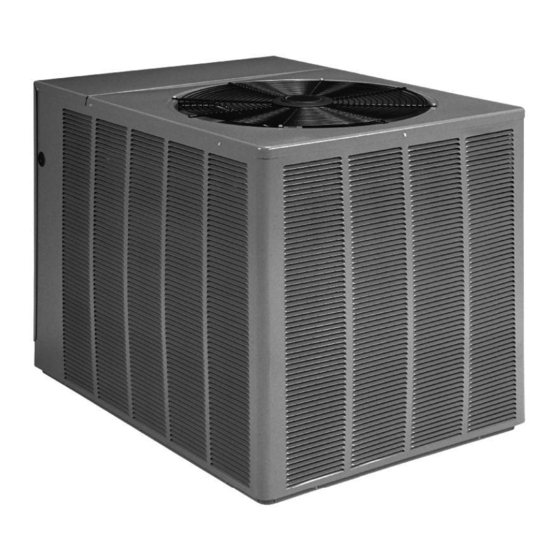
INSTALLATION INSTRUCTIONS
TWO-STAGE HEAT PUMP OUTDOOR UNITS
(-)PRL-JEC 16 SEER EQUIPPED WITH THE COMFORT CONTROL
SYSTEM™
!
R E C O G N I Z E T H I S S Y M B O L A S A N I N D I C A T I O N O F I M P O R T
!
W A R N I N G
THESE INSTRUCTIONS ARE INTENDED AS AN AID TO
QUALIFIED, LICENSED SERVICE PERSONNEL FOR PROPER
INSTALLATION, ADJUSTMENT AND OPERATION OF THIS
UNIT. READ THESE INSTRUCTIONS THOROUGHLY BEFORE
ATTEMPTING INSTALLATION OR OPERATION. FAILURE TO
FOLLOW THESE INSTRUCTIONS MAY RESULT IN IMPROPER
INSTALLATION, ADJUSTMENT, SERVICE OR MAINTENANCE
POSSIBLY RESULTING IN FIRE, ELECTRICAL SHOCK,
PROPERTY DAMAGE, PERSONAL INJURY OR DEATH.
P L E A S E R E A D C A R E F U L L Y A N D K E E P I N A S A F E P L A C E F O R F U T U R E R E F E R E N C E B Y A S E R V I C E M A N
[ ] INDICATES METRIC CONVERSIONS
D O N O T D E S T R O Y T H I S M A N U A L
A N T S A F E T Y I N F O R M A
ISO 9001:2008
SUPERSEDES 92-20522-63-05
2
T I O N !
92-20522-63-06
Advertisement
Table of Contents
Troubleshooting

Related Manuals for Rheem R-410A


Summary of Contents for Rheem R-410A
-
Page 1: Installation Instructions
INSTALLATION INSTRUCTIONS TWO-STAGE HEAT PUMP OUTDOOR UNITS (-)PRL-JEC 16 SEER EQUIPPED WITH THE COMFORT CONTROL SYSTEM™ R E C O G N I Z E T H I S S Y M B O L A S A N I N D I C A T I O N O F I M P O R T A N T S A F E T Y I N F O R M A T I O N ! W A R N I N G... -
Page 2: Table Of Contents
Specification of R-410A ........ -
Page 3: Safety Information
1.0 SAFETY INFORMATION WARNING THESE INSTRUCTIONS ARE INTENDED AS AN AID TO QUALIFIED, LICENSED SERVICE PERSONNEL FOR PROPER INSTALLATION, ADJUSTMENT AND OPERATION OF THIS UNIT. READ THESE INSTRUCTIONS THOROUGHLY BEFORE ATTEMPTING INSTALLATION OR OPERATION. FAILURE TO FOL- LOW THESE INSTRUCTIONS MAY RESULT IN IMPROPER INSTALLATION, ADJUSTMENT, SERVICE OR MAINTENANCE POSSIBLY RESULTING IN FIRE, ELECTRICAL SHOCK, PROPERTY DAMAGE, PERSONAL INJURY OR DEATH. - Page 4 CAUTION R-410A systems operate at higher pressures than R-22 systems. Do not use R-22 service equipment or components on R-410A equipment. CAUTION Only use evaporators approved for use on R-410A systems. Use of existing R-22 evaporators can introduce mineral oil to the R-410A refrigerant form- ing two different liquids and decreasing oil return to the compressor.
-
Page 5: General Information
2.0 GENERAL INFORMATION WARNING The (-)PRL-series of heat pump are designed to operate using the Comfort Control System™ or traditional 24VAC controls. These units are equipped with the Comfort THE MANUFACTURER’S WAR- System™. To take full advantage of the Comfort Control System™, the RANTY DOES NOT COVER ANY preferred method of installation is using the Comfort Control... -
Page 6: Dimensions
BTUH x 1000 (NOMINAL CAPACITY) 024 = 24,000 BTU/HR 036 = 36,000 BTU/HR ACCESS 048 = 48,000 BTU/HR PANEL 060 = 60,000 BTU/HR DESIGN SERIES R-410A 16 SEER AIR INLETS (LOUVERS) ALLOW 24” [610 mm] ALLOW 6” [152 mm] REMOTE HEAT PUMP SERVICE ACCESS MIN. -
Page 7: Electrical And Physical Data
2.4 Electrical And Physical Data TABLE 1 (-)PRL ELECTRICAL AND PHYSICAL DATA ELECTRICAL PHYSICAL Fuse or HACR Model Compressor Outdoor Coil Weight Fan Motor Minimum Refrig. Circuit Breaker Phase Number Full Load Circuit Frequency (Hz) Rated Load Locked Rotor Amperes Ampacity Circuit RPRL-... -
Page 8: Heat Pump Location
Several different types of protective coatings are offered in some areas. These coatings may provide some benefit, but the effectiveness of such coating materials cannot be verified by the equipment manufacturer. 3.2 Heat Pump Location Consult local and national building codes and ordinances for special installation requirements. -
Page 9: Factory-Preferred Tie-Down Method
All units are factory charged with Refrigerant 410A. All models are supplied with service valves. Keep tube ends sealed until connection is to be made to prevent system contamination. 4.1 Tools Required For Installing & Servicing R-410A Models Manifold Sets: -Up to 800 PSIG High side... -
Page 10: Specification Of R-410A
R-410A and air should never be mixed in tanks or supply never be done with a mixture of R-410A and air. Leak checking can be per- lines, or be allowed to accumulate in storage tanks. Leak checking should formed safely with nitrogen or a mixture of R-410A and nitrogen. -
Page 11: Replacement Units
CAUTION Only use evaporators approved for use on R-410A systems. Use of existing R-22 evaporators can introduce mineral oil to the R-410A refrigerant forming two differ- ent liquids and decreasing oil return to the compressor. -
Page 12: Maximum Length Of Lines
Any debris in the line set will end up plugging the expansion device. • As an added precaution, a high quality filter drier is standard on R-410A units. • Do not allow the vapor line and liquid line to be in contact with each other. This causes an undesirable heat transfer resulting in capacity loss and increased power consumption. - Page 13 NOTES: Using suction line larger than shown in table will result in poor oil return and is not recommended. TABLE 5 LIQUID LINE SIZING – DUAL SPEED HEAT PUMP 2-Stage Line Size Liquid Line Size R-410A Line Size Outdoor unit Above or Below Indoor Coil Connection System (Inch O.D.)
-
Page 14: Tubing Connections
7.5 Tubing Connections Indoor coils have only a holding charge of dry nitrogen. Keep all tube ends sealed until connections are to be made. • Use type “L” copper refrigeration tubing. Braze the connections with the follow- ing alloys: – copper to copper - 5% –... -
Page 15: Defrost Termination
8.2 Defrost Termination Once a defrost is initiated, the defrost will continue until fourteen minutes has elapsed or the coil temperature has reached the terminate temperature. The termi- nate temperature is factory set at 70°F, although the temperature can be changed to 50°F, 60°F, 70°F or 80°F by relocating dip switches on the ICC. -
Page 16: High & Low Pressure Controls (Hpc And Lpc)
11.0 HIGH AND LOW PRESSURE CONTROLS 11.0 (HPC AND LPC) These controls keep the compressor from operating in pressure ranges which can cause damage to the compressor. Both controls are in the low voltage control cir- cuit. High pressure control (HPC) is an automatic-reset which opens near 610 PSIG and closes near 420 PSIG. -
Page 17: Control Description
12.0 CONDENSING UNITS EQUIPPED WITH THE 12.0 OMFORT ONTROL SYSTEM™ The Comfort Control is the next generation of the Integrated Compressor Control (ICC) and is an integral part of the Comfort Control System™ with the following features: 12.1 Control Description (see Figure 4) Dual 7-Segment LED •... - Page 18 Thermostat Connector (E2) • R – 24VAC from the indoor unit 24VAC transformer (40 VA minimum) • C – 24VAC Common from the indoor unit 24VAC transformer • 1-Data: System Communications Line 1 • 2-Data: System Communications Line 2 Low Volt Fuse •...
-
Page 19: Comfort Control Icc Control Operation
12.2 omfort ontrol Control Wiring The four 18AWG low voltage control wires must be installed from the thermostat to the indoor unit and from indoor unit to the outdoor unit. The wire length between the thermo- stat and indoor unit should not be greater than 100 feet. The wire length between the indoor unit and outdoor unit should not be greater than 125 feet. - Page 20 cooling operation, an upper case “C” is displayed on the 7-segment LEDs. 2) Second Stage Cooling Operation – When the ICC receives a command for second stage cooling operation, an upper case “C” is displayed on the 7-segment LEDs. Upper case “C” indicates second stage cooling operation 3) First Stage Heating Operation - When the ICC receives a command for first stage heating operation, “h1”...
-
Page 21: Active Compressor Protection Mode
• The 3-minute time delay can be bypassed when a command for compressor operation is present by pressing the TEST button for 1 second and releasing. The compressor will begin operation and the dual 7-segment will stop flashing. 3 3 0 0 S S e e c c o o n n d d M M i i n n i i m m u u m m R R u u n n T T i i m m e e r r •... - Page 22 If the HPC opens three (3) times during the same command for unit operation, the ICC • above 5°F before performing further diagnostics. will lockout the compressor to keep it from continuing to operate and flash a L” on the 7- segment LEDs followed by a “29”.
-
Page 23: Test And Fault Recall Modes
If the ICC detects current in the start circuit without current present in the run cir- cuit, , the ICC will lockout the compressor to keep it from continuing to operate and flash a “L” on the dual 7-segment LEDs followed by a “07”. I I M M P P O O R R T T A A N N T T : : This mode of active protection must be manually reset. - Page 24 A maximum of six individual faults can be stored • • Each fault is displayed one time with the top right hand segment of the dual 7- A maximum of three consecutive identical faults are stored. • segment display activated between faults. A “0”...
-
Page 25: Icc Diagnostic Codes
12.6 OMFORT ONTROL SYSTEM™ CONTROL WIRING 13.X ICC Diagnostic Codes CONVENTIONAL THERMOSTAT WIRING 13.X ICC Diagnostic Codes 13.X ICC Diagnostic Codes 13.X ICC Diagnostic Codes 13.X ICC Diagnostic Codes 13.X ICC Diagnostic Codes ICC DIAGNOSTIC CODES Descriptions of the ICC diagnostic codes are provided below: ICC Diagnostic Codes Descriptions of the ICC diagnostic codes are provided below: Descriptions of the ICC diagnostic codes are provided below:... - Page 26 DESCRIBE d3 – Airflow CFM Mismatch DESCRIBE DESCRIBE • Misapplied/wrong indoor air mover – replace DESCRIBE DESCRIBE proper system operation The indoor air mover (air handler/furnace) with properly sized air handler/furnace. P – Protector Trip • Motor protector open cannot supply the required airflow for d3 –...
- Page 27 Dual 7-Segment Status/Possible Cause – Troubleshooting LEDs Display Diagnostic Description 21 – Low Pressure Control Open 21 – Low Pressure Control Open • Unit has low refrigerant charge • Unit has low refrigerant charge Information 21 – Low Pressure Control Open •...
-
Page 28: Conventional 24Vac Thermostat Control Wiring
compressor 21 – Low Pressure Control Open • Unit has low refrigerant charge 01 – Long Run Time (Compressor) • Low refrigerant charge The ICC detects the LPC is open. • Indoor coil is frozen (cooling mode) Dual 7-Segment The compressor has continuously run for Status/Possible Cause –... - Page 29 A thermostat and a 24-volt, 40VA minimum transformer are required for the control circuit of the condensing unit. The furnace or the air handler transformer may be used if sufficient. See the wiring diagram for reference. Use Table 6 to size the 24- volt control wirings.
-
Page 30: Icc Control Operation With Conventional Thermostat Wiring
INSERT FIGURES 7 THRU 10 HERE FR SECTION 13.4 HERE!!!! 12.9 ICC Control Operation with Conventional Thermostat Wiring 13.X ICC Control Operation with Conventional Therm I I n n s s t t a a l l l l a a t t i i o o n n V V e e r r i i f f i i c c a a t t i i o o n n •... - Page 31 4 4 ) ) S S e e c c o o n n d d S S t t a a g g e e H H e e a a t t i i n n g g O O p p e e r r a a t t i i o o n n - When the ICC receives a call for second stage heating operation, “H”...
-
Page 32: Active Compressor Protection Mode
The ICC starts/stops the outdoor fan one (1) second after the start/stop of the compressor • upon a call for compressor operation to minimize current inrush and/or voltage drop. 13.X Active Compressor Protection Mode 12.10 Active Compressor Protection Mode • The ICC actively protects the compressor from harmful operation during a fault The ICC actively protects the compressor from harmful operation during a fault condition. - Page 33 If the HPC opens three (3) times during the same call for unit operation, the ICC will • lockout the compressor to keep it from continuing to operate and flash a L” on the 7- segment LEDs followed by a “29”. Active Protection –...
-
Page 34: Test And Fault Recall Modes
IMPORTANT: This mode of active protection must be manually deactivated. I I M M P P O O R R T T A A N N T T : : This mode of active protection must be manually reset. Exiting Active Compressor Protection Lockout E E x x i i t t i i n n g g A A c c t t i i v v e e C C o o m m p p r r e e s s s s o o r r P P r r o o t t e e c c t t i i o o n n L L o o c c k k o o u u t t Three are three methods to reset the ICC after an active protection lockout: Three are three methods to reset the ICC after an active protection lockout:... - Page 35 • Each fault is displayed one time with the top right hand segment of the dual 7- segment display activated between faults. • Each fault is displayed with the most recent fault displayed first. • A maximum of six individual faults can be stored •...
-
Page 36: Electrical Wiring
13.0 ELECTRICAL WIRING NOTE: Check all wiring to be sure connections are securely fastened, electrically isolated from each other and that the unit is properly grounded. Field wiring must comply with the National Electric Code (C.E.C. in Canada) and any applicable local code. 13.1 Power Wiring It is important that proper electrical power from a commercial utility is available at the condensing unit contactor. -
Page 37: Checking Airflow
16.1 Charging units with R-410A Refrigerant Charge for all systems should be checked against the Charging Chart inside the... -
Page 38: Charging By Liquid Pressure
IMPORTANT: Do not operate the compressor without charge in system. Addition of R-410A will raise pressures (vapor, liquid and discharge). If adding R-410A raises both vapor pressure and temperature, the unit is over- charged. IMPORTANT: Use industry-approved charging methods to ensure proper system charge. -
Page 39: Accessories
17.0 ACCESSORIES WARNING 17.1 Dual Fuel Kit Model (Part No. RXME-A01) This kit is required if this unit is installed in a dual fuel application. TURN OFF ELECTRIC POWER AT THE FUSE BOX OR SERVICE PANEL BEFORE MAKING ANY 17.2 Remote Outdoor Temperature Model (Part No. 47-102709-03) ELECTRICAL CONNECTIONS. -
Page 40: Replacement Of Comfort Control System™ Control Board
ADVANCED SETTINGS All adjustments for airflow are made at the thermostat at this point. Items that can be changed are Airflow trim adjustment Dehumidification Setpoint and mode of operation. The thermostat also has a wide range of fault and history information. The following tables show all of the available options by unit type. -
Page 41: Electrical Checks Flow Chart
18.3 Electrical Checks Flow Chart Thermostat call For cooling, no cooling Outdoor Unit Running? Refer to panel cover/documentation for Fault Code Troubleshooting. Check fault history for other faults. Check control voltage (R and C) 7-Segment display lit? to control No call received. Y1 LED lit? 24V Systems: Check thermostat, control wiring... -
Page 42: Cooling Mechanical Checks Flow Chart
18.4 Cooling Mechanical Checks Flow Chart Unit Running? Go to Electrical Pressure problems? Checks Flow Chart High Head Pressure Low Head Pressure Low Suction Pressure Dirty Outdoor Coil Low on Charge Dirty Filters Inoperative Outdoor Fan Open IPR Valve Dirty Indoor Coil Overcharge Low Ambient Temperature Inadequate Indoor Air Flow... -
Page 43: Defrost Mechanical Checks Flow Chart
18.5 Defrost Mechanical Checks Flow Chart DEFROST SYSTEM No Defrost Incomplete Defrost Excessive Defrost Reversing Valve Stuck Poor Sensor Location Wrong Defrost Timer Setting Poor Sensor Location Failed Defrost Relay Low System Charge (doesn’t stop O.D. Fan) Welded Rev Valve Thermostat Satisfies Wind Affecting Relay... -
Page 44: General Troubleshooting Chart
18.6 General Trouble Shooting Chart WARNING DISCONNECT ALL POWER TO UNIT BEFORE SERVICING. CONTACTOR MAY BREAK ONLY ONE SIDE. FAILURE TO SHUT OFF POWER CAN CAUSE ELECTRICAL SHOCK RESULTING IN PERSONAL INJURY OR DEATH. SYMPTOM POSSIBLE CAUSE REMEDY Unit will not run •... -
Page 45: Service Analyzer Charts
18.7 Service Analyzer Charts COMPRESSOR OVERHEATING SYMPTOMS POSSIBLE CAUSE CHECK/REMEDIES High superheat Low charge Check system charge Faulty metering device Restricted cap tube, TEV (TXV) Power element superheat adjustment Foreign matter stopping flow High internal load Hot air (attic) entering return Heat source on;... - Page 46 SYMPTOMS POSSIBLE CAUSE CHECK OR REMEDIES Short cycling of compressor (cont.) Low charge Check system charge Low evaporator air flow Dirty coil Dirty filter Duct too small or restricted Faulty run capacitor Replace Faulty internal overload Replace compressor Faulty Compressor Valves Fast equalization/ Replace compressor and examine Low pressure difference...
- Page 47 LOSS OF LUBRICATION SYMPTOMS POSSIBLE CAUSE CHECK OR REMEDIES Compressor failures Line tubing too long Add oil to the recommended level Line tubing too large Reduce pipe size to improve oil return Low suction pressure Low charge Check system charge Refrigerant leaks Repair and recharge Cold, Noisy compressor - Slugging...
- Page 48 THERMOSTATIC EXPANSION VALVES SYMPTOMS POSSIBLE CAUSE CHECK OR REMEDIES High Superheat, Low Suction Pressure Moisture freezing and blocking valve Recover charge, install filter-drier, evacuate system, recharge Dirt or foreign material blocking valve Recover charge, install filter-drier, evacuate system, recharge Low refrigerant charge Correct the charge Vapor bubbles in liquid line Remove restriction in liquid line...
- Page 49 THERMOSTATIC EXPANSION VALVES SYMPTOMS POSSIBLE CAUSE CHECK OR REMEDIES Superheat is low to normal Unequal evaporator circuit loading Ensure air flow is equally distributed with low suction pressure through evaporator Check for blocked distributor tubes Low load or airflow entering Ensure blower is moving proper air evaporator coil Remove/Correct any air flow...
-
Page 50: Subcooling Calculation
1. Measure the liquid pressure at the liquid line service valve. TABLE 8 TEMPERATURE PRESSURE CHART 2. Convert the liquid line pressure to saturated temperature. See Table 8. TEMP R-410A 3. Measure the liquid line temperature at the liquid line service valve. (Deg. F) PSIG -150 —... -
Page 51: Wiring Diagrams
19.0 WIRING DIAGRAMS FIGURE 11 WIRING DIAGRAM FOR 2, 3, & 4 TON... - Page 52 FIGURE 12 WIRING DIAGRAM FOR 5 TON CM 0610...