Samsung AQB18J6WC Service Manual
Split-type air conditioner
Hide thumbs
Also See for AQB18J6WC:
- Installation manual (16 pages) ,
- Service manual (122 pages) ,
- User manual (26 pages)
Table of Contents
Advertisement
AIR CONDITIONER
AQV18JA, AQV24JA
AQV18JAX, AQV24JAX
Refer to the service manual in the GSPN(see the rear cover) for the more information.
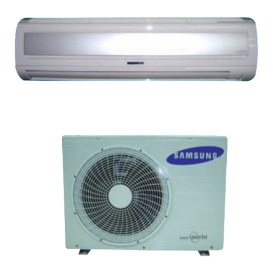
SPLIT-TYPE AIR CONDITIONER
INDOOR UNIT
Basic : AQB18J6WC
AQB24J2WC
Model : AQV18JA
AQV24JA
Model Code : AQV18JA
AQV24JA
THE FEATURE OF PRODUCT
High Energy Efficiency BLDC
Air Conditioner
Simple Flat Grille Design
good' sleep Mode
: good' sleep Mode can help you sleep quickly and
soundly and wake up refreshed.
Multi Functional Cleaning System
: Silver Nano Health System and Deodorizing/
Catechin Filter are adopted.
Silence Mode
: When you use the "Silence Mode", you can
experience extremely quiet operation of your
air conditioner.
OUTDOOR UNIT
AQV18JAX
AQV24JAX
Advertisement
Table of Contents

Related Manuals for Samsung AQB18J6WC


Summary of Contents for Samsung AQB18J6WC
-
Page 1: Air Conditioner
SPLIT-TYPE AIR CONDITIONER INDOOR UNIT OUTDOOR UNIT Basic : AQB18J6WC AQB24J2WC Model : AQV18JA AQV24JA Model Code : AQV18JA AQV18JAX AQV24JA AQV24JAX AIR CONDITIONER THE FEATURE OF PRODUCT High Energy Efficiency BLDC Air Conditioner Simple Flat Grille Design ... -
Page 2: Table Of Contents
5-4 Ass’y Control Out ..........................16. Wiring Diagram ..........................6-1 Indoor Unit ............................6-2 Outdoor Unit ............................ 17. Schematic Diagram ........................7-1 Indoor Unit ............................7-2 Outdoor Unit ............................ 18. Circuit Descriptions ........................8-1 PCB Circuit Descriptions ........................Samsung Electronics... - Page 3 13-2 Low Refrigerant Pressure Distribution 13-2 ..................13-3 Pressure & Capacity mark 13-3 ......................13-4 Q & A for Non-trouble 13-4 ........................13-5 Cleaning/Filter Change 13-7 ......................... 13-6 Installation 13-9 ............................13-7 Installation Diagram of Indoor Unit and Outdoor Unit 13-10 ............Samsung Electronics...
-
Page 4: Precautions
Do not place a cloth or other materials over it. Remove the batteries if you don’t use the remote control for a long time. (If applicable) Use the remote control within 23ft(7m) from the indoor unit. (If applicable) Samsung Electronics... -
Page 5: Disposing Of The Unit
Young children or infirm persons should be always supervised when they use the air conditioner. Max current is measured according to IEC standard for safety. Current is measured according to ISO standard for energy efficiency. Samsung Electronics... -
Page 6: Product Specifications
Mode can help you sleep quickly and soundly and wake up refreshed. Multi functional cleaning system With Silver Nano Health System and Deodorizing/Catechin Filters makes your room more refreshed. Silence Mode When you use the “Silence Mode”, you can experience extremely quiet operation of your air conditioner. Samsung Electronics... -
Page 7: Product Specifications
-10°C to 46°C approx. Operation conditon range 80°F or less 80°F or less indoor 27°C or less 27°C or less heating 5°F to 75°F approx. 5°F to 75°F approx. Outdoor -15°C to 24°C approx. -15°C to 24°C approx. Samsung Electronics... -
Page 8: The Comparative Specifications Of Product
AQB18J* : 58 Outdoor Unit AQV24J* : 60 AQB24J* : 60 Silver Nano Coated Evaporator Silver Nano Coated Evaporator Air Purifying System Filter Bio Filter Bio Filter Deodorizing Fiter Deodorizing Fiter Indoor Display 3 LED Display 3 LED Display Samsung Electronics... -
Page 9: Accessory And Option Specifications
2-4-1 Accessories Item Descriptions Code-No. Q'TY Remark Ass'y Plate Hanger DB90-02738A Remote Control DB93-03012N Batteries for Remote Control DB47-90024A Indoor Unit User’s Manual DB98-27555A Installation Manual DB98-27556A Service Manual DB98-27558A Drain Plug DB67-20011A Outdoor Unit Rubber Leg DB73-20134A Samsung Electronics... -
Page 10: Alignment And Adjustments
* After the test operation is finished, you cannot retry the test operation without power reset. * The blade places to set position and then the indoor fan operates. * The Compressor is operated by rated frequency before sixty minutes or enforced stop. Samsung Electronics... -
Page 11: Indoor Display Error And Check Method
(open or short) Indoor fan motor malfunction 3-4P EEPROM error Option Setting Option error Option Setting (option wasn’t set up or option data error) Remote Control on/off Outdoor unit error Outdoor Unit Power Reset Lamp on, Lamp off, Lamp blink Samsung Electronics... -
Page 12: Outdoor Led Error Display And Check Method
DC-Link voltage sensor error I_Trip error / PFC Over current GAS Leak error AC Line Zero Cross Signal out Power ON reset(1sec) Capacity miss match Test Operation at Cooling Mode Test Operation at Heating Mode LED ON, LED OFF, LED BLINK Samsung Electronics... -
Page 13: Setting Option Setup Method
Setting Option SEG4. Push the button to set the display panel to Every time you push the button, the display panel reads . . . repeatedly. �� Samsung Electronics �� ��... - Page 14 . . . repeatedly. Setting Option SEG10. Push the button to set the display panel to Every time you push the button, the display panel reads . . . repeatedly. Samsung Electronics...
-
Page 15: Option Items
If the unit is not working properly or all lamps are continuously flickering after setting the option code, see if the correct option code is set up for its model. OPTION ITEMS REMOCON SEG1 SEG2 SEG3 SEG4 SEG5 SEG6 SEG7 SEG8 SEG9 SEG10 SEG11 SEG12 MODEL AQV18JA AQV24JA Samsung Electronics... -
Page 16: Disassembly And Reassembly
4. Disassembly and Reassembly Necessary Tools Item Remark +SCREW DRIVER MONKEY SPANNER Samsung Electronics... -
Page 17: Indoor Unit
3) Loosen 1 of the right screw(CCW) and detach the Terminal Cover. (Use +Screw Driver.) 4) Detach the thermistor from the Front Grille. 5) Loosen 2 fixing screws(CCW) of Front Grille. 6) Unlock 3 hooks to fix Panel Front and Tray Drain. (Use +Screw Driver.) Samsung Electronics... - Page 18 2) Detach the outdoor unit connection wire from the Terminal Block. 3) Loosen 4 fixing screws(CCW) of Ass'y Control-In. (Use +Screw Driver.) You can disassembly Ass'y Control In without evaporator disassembled. Tray Drain 1) Pull Tray Drain out from the Back Body. Samsung Electronics...
- Page 19 Evaporator from indoor unit. Fan Motor 1) Loosen the fixing screw(CCW). & (Use +Screw Driver.) Cross Fan 2) Detach the Fan Motor from the Fan. 3) Detach the Fan From the left Holder Bearing. Samsung Electronics...
-
Page 20: Outdoor Unit
1) Loosen 1 fixing screw(CCW) of the Cover- Control and detach the Cover Control. 2) Loosen fixing screws(CCW) and detach the Cabinet-Upper. 3) Loosen 1 screw(CCW) fixed to assemble Control Box with Cabinet-Side RH. 4) Loosen 6 fixing screws(CCW) and detach the Cabinet-Side RH. Samsung Electronics... - Page 21 Disassembly and Reassembly Parts Procedure Remark 5) Loosen 2 screws(CCW) fixed on the Guide Condenser. 6) Loosen fixing screws(CCW) of the Cabinet Front. Samsung Electronics...
- Page 22 Motor 2) Detach the Fan Propeller. 3) Loosen 4 fixing screws(CCW) to detach the Motor. 4) Disconnect the wire between Ass’y Control Out and Motor. 5) Loosen 2 fixing screws(CCW) and detach the Bracket Motor. Samsung Electronics...
- Page 23 Compressor 1) Loosen the fixing nut(CCW) and detach the Compressor Lead Wire. 2) Disassemble the Felt Comp Sound. 3) Loosen the 3 bolts(CCW) at the bottom of Compressor like the picture on the right side. Samsung Electronics...
- Page 24 MEMO Samsung Electronics...
-
Page 25: Exploded Views And Parts List
5-1 Indoor Unit � � � ��� �� ��� �� �� �� �� �� � ��� ��� ��� � � ��� ��� ��� ��� � ��� ��� ��� ��� ��� ��� ��� ��� ��� ��� ��� ��� � � Samsung Electronics... - Page 26 HOLDER-PIPE HIPS,T2.5 DB63-01063D COVER-CONTROL ABS 5V,T2.5 DB93-03012N ASS’Y REMOCON ARH-1409 DB96-03817A ASS’Y EVAP-SUPPORT ASS’Y DB31-00267A MOTOR FAN 220-240V~, 50/60Hz, Class E DB94-00456B ASS’Y-CROSS FAN ASS’Y DB97-02075A ASS’Y-BOLT SPECIAL ASS’Y DB94-00455A ASS’Y BEARING-RUBBER ASS’Y DB90-02082A ASS’Y COVER PCB SGCC-M,T0.4 Samsung Electronics...
-
Page 27: Outdoor Unit
5-2 Outdoor Unit Samsung Electronics... -
Page 28: Parts List
VALVE EXPANSION BODY FUJIKOKI 20-3 DB62-02283A VALVE SERVICE R410A, SANHUA, 1/4” DB61-00821B GUIDE SCREEN P.E.H 100% DB93-04346B ASS’Y CONTROL OUT ASS’Y DB93-04346A ASS’Y CONTROL OUT ASS’Y DB32-00176A THERMISTOR OUT/DIS ASS’Y DB32-00175A THERMISTOR COND ASS’Y DB39-01301A CONNECT WIRE COMP ASS’Y Samsung Electronics... -
Page 29: Ass'y Control In
DB93-04832A CONNECT WIRE STEP MOTOR DB32-00020A SENSOR 4P(103AT) DB63-00851A COVER DRAIN DB73-00242B RUBBER BAND RUBBER DB39-00765T CONNECT WIRE DB39-01193A CONNECT WIRE SKYBLU,3P DB39-01210B CONNECT WIRE RED/BLU DB93-04685A CONNECT WIRE DISPLAY DB98-27584A LABEL CAUTION LABEL DB93-04257A ASSY PCB-INDOOR485 24K/18K(INDOOR) Samsung Electronics... - Page 30 MEMO Samsung Electronics...
-
Page 31: Ass'y Control Out
5-4 Ass'y Control Out AQV18JAX : DB93-04346B AQV24JAX : DB93-04346A Samsung Electronics... - Page 32 6002-000630 SCREW-TAPPING PH+,M2,L8 DB91-00306A ASSY-SCREW MACHINE PH+,M3,L16 DB91-00307A ASSY-SCREW MACHINE PH+,M4,L16 6002-000555 SCREW-TAPPING PH+,M4,L25 6009-001001 SCREW-SPECIAL TH+,M4,L8 6002-000560 SCREW-TAPPING PH+,M4,L10 DB61-00206B HOLDER-WIRE SGCC_M,T0.5 6002-000231 SCREW-TAPPING PH+,M4,L10 DB65-10088D CABLE-TIE NYLON66 DB95-01040E ASSY NOISE ABSORBER ASSY DB98-27584A LABEL CAUTION LABEL Samsung Electronics...
-
Page 33: Wiring Diagram
6. Wiring Diagram 6-1 Indoor Unit This Document can not be used without Samsung’s authorization. Samsung Electronics... -
Page 34: Outdoor Unit
6-2 Outdoor Unit This Document can not be used without Samsung’s authorization. Samsung Electronics... -
Page 35: Schematic Diagram
7. Schematic Diagram 7-1 Indoor Unit This Document can not be used without Samsung’s authorization. Samsung Electronics 7 -1... -
Page 36: Outdoor Unit
7-2 Outdoor Unit This Document can not be used without Samsung’s authorization. Samsung Electronics... -
Page 37: Circuit Descriptions
8-1-1 Indoor Unit SMPS PART BUZZER PART INDOOR FAN CONTROL SUB PCB CONNECTOR ZERO CROSSING PART DISPLAY PART STEP MOTOR & ION INDOOR TEMPERATURE SENSOR MPI PART HUMID PART This Document can not be used without Samsung’s authorization. Samsung Electronics... - Page 38 Circuit Descriptions Circuit Descriptions 8-1-2 Outdoor Unit TEMPERATURE SENSOR & EEV SMPS INVERTER This Document can not be used without Samsung’s authorization. Samsung Electronics...
-
Page 39: Refrigerating Cycle Diagram
8-2 Refrigerating Cycle Diagram Indoor Unit Outdoor Unit 2 way valve Expansion valve Liquid side Heat Exchanger (Evaporator) Heat Exchanger (Condenser) Cross Fan Gas side 4 way valve 3 way valve Cooling Compressor Heating Gas Leak Check Point Samsung Electronics... -
Page 40: Pcb Diagram
9. PCB Diagram 9-1 Indoor PCB The red number connecter is not used. Power Temperature Sensor Motor RPM Feedback Auto Grill Remocon Module HVPS(High voltage Generator) Humidity Sensor BLADE-H Step Motor Anions Display Indoor Fan Motor Samsung Electronics... -
Page 41: Outdoor Inverter Pcb
9-2 Outdoor Inverter PCB The red number connecter is not used. Power N COND/OLP Temperature Sensor Power L DIS/OUT Temperature Sensor BLDC FAN EEV Connector AC FAN Comp. Connector Wire Communication 485 Reactor Connector Wire Samsung Electronics... - Page 42 MEMO Samsung Electronics...
-
Page 43: Operating Instructions
10-1 Name of Each Part Air Inlet Temperature sensor Air filter Air flow blades (under the grille) (outlet) Operation indicator (GREEN) Timer indicator (GREEN) Turbo indicator (RED) On/Off button Air Inlet (Rear) Air Outlet Connection Valve (Inside) 10-1 Samsung Electronics... -
Page 44: Wireless Remote Control-Buttons And Display
(AUTO, COOL, DRY, FAN, HEAT) Temperature adjustment button Fan speed adjustment Energy Saving button button & Silence mode button Airflow control button Good Sleep button Timer Set/Cancel button On Timer button Battery check button Off Timer button Samsung Electronics 10-2... -
Page 45: Main Function
Medium High Maximum Heat Mode Press the button on the remote control until is displayed. Press the button to select the fan speed until the required setting is displayed. Automatic (rotated : Silence mode Medium High Maximum 10-3 Samsung Electronics... - Page 46 You can select the Turbo function in the Auto, Cool and Heat mode. If you select this function in the Dry or Fan mode, it will return to the Auto mode. good' sleep Press the button until the indicator appears on the remote con- Mode trol. Samsung Electronics 10-4...
-
Page 47: Troubleshooting
The compressor operates in a reverse cycle to remove Indoor fan and outdoor fan stop operation intermittently exterior ice in a HEAT mode, and indoor fan and outdoor in a HEAT mode. fan do not operate intermittently for within 20% of the total heater operation 11-1 Samsung Electronics... -
Page 48: Fault Diagnosis By Symptom
Replace fuse FUSE(F701) : T3.15[A]/250[V] Check the output of SMPS on the control board. Input power: AC230±15%[V] PCB should be replaced IC02 Input: DC12[V] IC02 output: DC5[V] Check the setting temperature Samsung Electronics 11-2... -
Page 49: The Outdoor Unit Power Supply Error
Is there no error at the insertion of PCB? Exchange the PCB. Exchange the PCB. Are the BLDC FAN Wire Is the +,- of C102 short? 1 and 3 short? Exchange the PCB. Exchange the BLDC FAN. Normal Operation Exit 11-3 Samsung Electronics... - Page 50 Voltage at pin #30~#34 of micom (IC04) Micom (IC04) is faulty. change?(Squarewave) Voltage at Driver IC05/06 (ULN2003A) is faulty. pin #2 ~ #5 of CN61(motor connector) change?(Squarewave) Up/Down louver motor is faulty. Samsung Electronics 11-4...
-
Page 51: Outdoor Pcb
Pull out the power cord and during the operation?(Square-Wave) execute the following step after 30 seconds. Disassemble the BLDC FAN Wire. Is the short between Exchange the PCB. the BLDC FAN Wires? Exchange the BLDC FAN MOTOR. Exchange the PCB. 11-5 Samsung Electronics... - Page 52 Pull out the power cord and exchange the PCB from the case after 30 seconds. Is the assembly of Micom and Exchange the PCB. peripheral circuit part good? Check again after assembly of PCB. Samsung Electronics 11-6...
- Page 53 4 way valve coil. Dose the voltage of AC 220V Exchange apply to the connector of 4 way the outdoor PCB. valve coil during the operation? Go to the next page 4 way valve main body error 11-7 Samsung Electronics...
- Page 54 Connect the connector. correctly? Check the resistance value Outdoor fan error of outdoor fan. Dose the voltage of DC300V apply to the connector of outdoor Check the motor wire. fan during the operation of outdoor unit? Outdoor PCB error Samsung Electronics 11-8...
-
Page 55: Outdoor Temperature Sensor Error
Exchange the sensor. (Refer to the R/T TABLE) Is the resistance value of sensor connection pull_up 18.2K? Exchange the PCB. Exchange the PCB. Normal operation Exit 400.0 350.0 300.0 250.0 200.0 150.0 100.0 50.0 11-9 Samsung Electronics... - Page 56 Exchange the sensor. (Refer to the R/T TABLE) Is the resistance value of sensor connection pull_up 24K? Exchange the PCB. Exchange the PCB. Normal operation Exit 600.0 500.0 400.0 300.0 200.0 100.0 Samsung Electronics 11-10...
-
Page 57: Coil Temperature Sensor Error
Exchange the sensor. (Refer to the R/T TABLE) Is the resistance value of sensor connection pull_up 18.2K? Exchange the PCB. Exchange the PCB. Normal operation Exit 400.0 350.0 300.0 250.0 200.0 150.0 100.0 50.0 11-11 Samsung Electronics... - Page 58 16.89 18.01 16.31 14.74 15.90 17.37 12.95 14.08 12.69 11.41 12.51 11.25 10.09 11.14 9.993 8.941 9.950 8.904 7.948 8.900 7.947 7.078 7.983 7.112 6.320 7.175 6.378 5.656 6.465 5.735 5.075 5.838 5.168 4.564 5.285 4.669 4.114 Samsung Electronics 11-12...
- Page 59 -1.1 55.0 131.0 -1.3 60.0 140.0 -1.4 65.0 149.0 -1.4 70.0 158.0 -1.6 75.0 167.0 -1.8 80.0 176.0 -1.8 85.0 185.0 -2.0 90.0 194.0 -2.2 95.0 203.0 -2.3 100.0 212.0 -2.3 105.0 221.0 -2.5 110.0 230.0 -2.7 Samsung Electronics 11-13...
-
Page 60: Fan Error
4) Is the resistance value of sensor connection pull_up correct? 2. Troubleshooting procedure Remove the Fan lock. Isn't the Fan locked? Is the connector connected correctly? Connect the connector. Is the color of Fan wire matched correctly? Exchange the Fan. Exchange the PCB. Normal operation Exit Samsung Electronics 11-14... - Page 61 1, 2 correct after power supply? Is the capacitor(C101, C102, C103) Connect the connector. for DC-Link assembled in accordance the specification? Are R113, R114, R115 470kohm? Exchange the PCB. Is R116 14.3kohm? Exchange the Fan. Exchange the PCB. Normal operation Exit 11-15 Samsung Electronics...
- Page 62 Is the position of temperature sensor Correct the sensor position or and the sensing value normal? exchange the sensor. Is the connection cable for Correct the cable connection. the compressor and power terminal normal? Exchange the PCB. Samsung Electronics 11-16...
-
Page 63: Communication Error
Correct the wrong wiring. and communication cable error? Is the connection of Correct the connection of communication cable normal? communication cable. Is it the outdoor Exchange the indoor/outdoor unit PCB. 2 Micom(Inverter + Main) model? Exchange the outdoor unit PCB. 11-17 Samsung Electronics... -
Page 64: Compressor Start Error
Exchange the compressor. compressor (u↔v, v↔w, w↔u) normal? Is the compressor body and Exchange the compressor. interphase resistance insulated? Is the connection cable for the Correct the cable connection. compressor and power terminal normal? Exchange the PCB. Samsung Electronics 11-18... -
Page 65: Compressor Lock Error
Exchange the compressor. compressor (u↔v, v↔w, w↔u) normal? Is the compressor body and Exchange the compressor. interphase resistance insulated? Is the connection cable for the Correct the cable connection. compressor and power terminal normal? Exchange the PCB. 11-19 Samsung Electronics... - Page 66 Is the resistance for the Exchange the PCB. detection of DC Link voltage normal? Is the resistance value of Exchange the PCB. DC Link discharge normal? Is the reactor insulation damaged? Exchange the PCB. Exchange the reactor. Samsung Electronics 11-20...
- Page 67 11-2-18 The others 1. AC Line Zero Cross Signal OUT – Check the assembly condition of peripheral part of IC21, ZD21, ZD20 and D200 on the PCB. 2. Capacity miss match – Check again the indoor unit option code. 11-21 Samsung Electronics...
-
Page 68: Pcb Inspection Method
2) The fan motor of the indoor unit doesn’t run. • Fan Motor Connector(CN72) is faulty 3) The power voltage between terminal #3 and #5 • ASS’Y Main PCB is faulty of the connector(CN72) is 0V. • Connection is faulty Samsung Electronics 11-22... -
Page 69: Outdoor Detailed Inspection Procedure
1) Is CN01 1, 3 over 250V? • Outdoor PCB Error 2) Is CN01 3, 5 within 1V~5V? • BLDC Motor Error 3) Is the voltage of CN01 6 changed? 4) Is the resistance of BLDC Motor 1, 3 opened after power off? 11-23 Samsung Electronics... -
Page 70: Main Part Inspection Method
∞, 0Ω . . . Open or Short Stepping Motor Measure the resistance between the red wire and each terminal wire with a tester. Normal About 300Ω at the normal temperature (20˚C ~ 30˚C) Abnormal ∞, 0Ω . . . Open or Short Samsung Electronics 11-24... -
Page 71: Block Diagram
: BLADE CONTROL SELECT(UP/DOWN) MELODY CONTROL PART SLEEP OPERATION DC5V VOLTAGE REGULATOR ANION SELECT SPEAKER AUTO CLEAN SELECT OPTION ENERGY SAVING SELECT DC12V SMPS POWER BLOCK SOUND ON/OFF SELECT DIGITAL ON/OFF DC5V DC12V AC230V AC INPUT DC25V 12-1 Samsung Electronics... - Page 72 Block Diagram INDOOR FAN CONTROL BUZZER CONTROL SMPS 485 COMMUNICATION SUB-PCB Samsung Electronics 12-2...
-
Page 73: Outdoor Unit
• 4 WAY CONTROL SIGNAL COMPRESSOR • PFC CONTROL SIGNAL • COMPRESSOR CONTROL(6P, BLDC) • LED CONTROL SIGNAL • INDOOR COMMUNICATION SIGNAL • 4 WAY VALVE SMPS • EEV INDOOR UNIT PFC CIRCUIT DC5V AC INPUT DC12V DC15V AC300V AC230V DC25V 12-3 Samsung Electronics... - Page 74 DIODE OUTDOOR FAN IGBT DC_LINK CAP SMPS Samsung Electronics 12-4...
-
Page 75: Reference Sheet
" digit for classification between indoor and outdoor. Indoor "N" & Outdoor "X". : Use the “ ” digit for KD models. "CKD" "1" & "SKD" "2". Except the RAC Export Models for China. 13-1 Samsung Electronics... -
Page 76: Low Refrigerant Pressure Distribution
10 minutes. Indoor Temp. Variation : 68°F(20°C)~90°F(32°C) Outdoor Temp. Variation : 23°F(-5°C)~113°F(45°C) Low Refrigerant Pressure Distribution AQV18JA Indoor Temperature 90℉ 85℉ 80℉ 75℉ 70℉ Outdoor Temperature[℉] AQV24JA Indoor Temperature 90℉ 85℉ 80℉ 75℉ 70℉ Outdoor Temperature[℉ ] Samsung Electronics 13-2... -
Page 77: Pressure & Capacity Mark
0.10197 0.73756 4.1868 14.286 0.0056146 0.42693 3.088 1.163 0.27778 3.9683 0.0015596 0.11859 0.85778 3.9302x10 -4 0.29307 0.06999 0.252 0.029885 0.21616 745.7 178.11 641.19 2,544.4 76.04 9.8067 2.3423 8.4322 33.462 0.013151 7.233 1.3558 0.32383 1.1658 4.6262 0.0018182 0.13826 13-3 Samsung Electronics... -
Page 78: Q & A For Non-Trouble
It occurs when the drain pump is plugged out or it is out of order. Check the power of the drain pump and the position of the drain hose, and when the pump is faulty, contact the drain pump manufacturer. Samsung Electronics do not manufacture drain pumps. - Page 79 Also, the remote controller may not work under intensive light from a 3-wave length lamp or a neon sign due to the EMI. In this case, take the remote controller closer to the receiver. 13-5 Samsung Electronics...
- Page 80 There is a cost table. But, our service engineer needs to visit to total up the cost correctly. When you move in, make sure to contact Samsung Electronics Service Center or Authorized Service Agent in advance to streamline the process.
-
Page 81: Cleaning/Filter Change
Hook Body Note : • If you have not used the air conditioner for a long period of time, set the fan going for three to four hours to dry the inside of the air conditioner thoroughly. 13-7 Samsung Electronics... - Page 82 3. Wash the filters with clean water, then dry them in the shade. Bio Filter 4. Insert the filters into the original position. Note : • You can change the position of filters with each other. 5. Close the front grille. Samsung Electronics 13-8...
-
Page 83: Installation
Electric and earth work shall meet the "Electric Facility Technology Standard" and the "Internal Wire Regulation" of the Electric Business Laws. Inspection & Trial Run Upon completion of the tests, you shall make a trial run while you explain the main functions of the air conditioner to finish the installation. 13-9 Samsung Electronics... -
Page 84: Installation Diagram Of Indoor Unit And Outdoor Unit
- At this time, especially check for gas leakage from the 3 way valve’s stem nuts, and from the service port cap. 8) For further detailed information how to check the low pressure after installation, Please refer to Page 3-1. Samsung Electronics 13-10... -
Page 85: Pump Down" Procedure
• Make sure you do not bend the connection pipes in the middle and store together with the cables. • Move the indoor and outdoor units to a new location. • Remove the mounting plate for the indoor unit and move it to a new location. 13-11 Samsung Electronics... - Page 86 Mideast & Africa http://mea.samsungportal.com © Samsung Electronics Co., Ltd. Mar. 2007. This Service Manual is a property of Samsung Electronics Co., Ltd. Printed in China. Any unauthorized use of Manual can be punished under applicable International and/or domestic law.