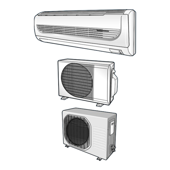
Samsung SH09ZW8X Service Manual
Hide thumbs
Also See for SH09ZW8X:
- Owner's instructions manual (26 pages) ,
- Owner's instructions manual (26 pages)
Advertisement
SERVICE
AIR CONDITIONER
ROOM AIR CONDITIONER
INDOOR UNIT
AQ12WHWE
AQ12WHWED
AQ09W8WE
SH12ZWHD
SH09ZW8
Manual
CONTENTS
OUTDOOR UNIT
UQ12WHWE
UQ12WHWED
UQ09W8WE
SH12ZWHDX
SH09ZW8X
Advertisement
Table of Contents

Related Manuals for Samsung SH09ZW8X


Summary of Contents for Samsung SH09ZW8X
-
Page 1: Table Of Contents
ROOM AIR CONDITIONER INDOOR UNIT OUTDOOR UNIT AQ12WHWE UQ12WHWE AQ12WHWED UQ12WHWED AQ09W8WE UQ09W8WE SH12ZWHD SH12ZWHDX SH09ZW8X SH09ZW8 SERVICE Manual AIR CONDITIONER CONTENTS 1. Product Specifications 2. Disassembly and Reassembly 3. Refrigerating Cycle Diagram 4. Set Up the Model Option 5. Troubleshooting 6. -
Page 2: Product Specifications
CAPILLARY TUBE Freezer Oil Capacity Refrigerant to Change(R410A) Protection Device(OLP) RBC12074-12500 RBC12188-12500 Cooling Test Condition INDOOR UNIT : DB27˚C WB19˚C OUTDOOR UNIT : DB35˚C WB24˚C INDOOR UNIT : DB32˚C WB23˚C OUTDOOR UNIT : DB43˚C WB26˚C Maximum Operation Condition Samsung Electronics... -
Page 3: Disassembly And Reassembly
2) Open the Front Grille by pulling right and left sides of the hook. 3) Loosen 1 of the right screw and detach the Terminal Cover. 4) Detach the thermistor from the Front Grille. 5) Loosen 2 fixing screws of Front Grille. Samsung Electronics... - Page 4 1) Take all the connector of PCB upper side (Main PCB) out. (Inclusion Power Cord) 2) Detach the outdoor unit connection wire from the Terminal Block. 3) Loosen 4 fixing screws of Ass'y Control-In. Tray Drain 1) Pull Tray Drain out from the Back Body. Samsung Electronics...
- Page 5 1) Loosen the fixing screw and detach the Fan Motor & Motor Holder. Cross Fan 2) Detach the Fan Motor from the Fan. 3) Detach the Fan From the left Holder Bearing. Samsung Electronics...
- Page 6 Cabinet-Side edge and a fixing screw on the Cabinet-Front lower to detach the Cabinet-Front. 2) Loosen 2 fixing screws of the Ass'y-Control. 3) Loosen 6 fixing screws of the Cabinet-Side 4) Loosen 2 fixing screws of the Cabinet-Side Samsung Electronics...
- Page 7 3) Disassemble the pipe in both inlet and outlet of the Compressor with welding torch. 4) Disassemble the pipe in both inlet and outlet of the Condenser with welding torch. 5) Loosen the 3 bolts at the bottom. 6) Detach the Compressor. Samsung Electronics...
- Page 8 Cover Control. 3) Loosen 8 fixing screws of the Cabi-Front and take off the Cabi-Front. 4) Loosen the fixing screws of the Assy Control Out. 5) Loosen the fixing screws of the Assy Cabi-side and take off the Cabi-side. Samsung Electronics...
- Page 9 3) Disassemble the pipe in both inlet and outlet of the Compressor with welding torch. 4) Disassemble the pipe in both inlet and outlet of the Condenser with welding torch. 1) Loosen the 3 bolts at the bottom. 2) Detach the Compressor. Samsung Electronics...
-
Page 10: Refrigerating Cycle Diagram
3-1 Refrigerating Cycle Diagram Outdoor Unit Indoor Unit Note Capillary tube Check valve 2-Way valve Liquid side Capillary tube Heat Heat Exchanger Exchanger (Evaporator) (Evaporator) Gas side 3-Way valve 4-Way valve Cooling Heating Compressor Gas Leak Check Polnt Samsung Electronics... -
Page 11: Set Up The Model Option
Every time you push the button, the display panel reads . . . repeatedly. Setting Option SEG4. Push the button to set the display panel to Every time you push the button, the display panel reads . . . repeatedly. Samsung Electronics... - Page 12 Every time you push the button, the display panel reads . . . repeatedly. Setting Option SEG10. Push the button to set the display panel to Every time you push the button, the display panel reads . . . repeatedly. Samsung Electronics...
- Page 13 If all lamps of indoor unit are flickering, Plug out, plug in power plug again and press ON/OFF key to retry. If the unit is not working properly or all lamps are continuously flickering after setting the option code, see if the correct option code is set up for its model. Samsung Electronics...
- Page 14 4-2 Table of the option Code 4-2 Table of the option Code 4-2 Table of the option Code Option Code Model SEG1 SEG2 SEG3 SEG4 SEG5 SEG6 SEG7 SEG8 SEG9 SEG10 AQ12WHWE[D ]/SH12ZWHD(X) AQ09W8WE/SH09ZW 8(X) Samsung Electronics...
-
Page 15: Troubleshooting
The compressor stops intermittently or the fan speed of the The compressor stops intermittently in a COOL mode or indoor unit decreases to prevent inside/outside air frozen DRY mode, and fan speed of the indoor unit decreases. depending on the inside/outside air temperature. Samsung Electronics... - Page 16 Problem with the outdoor unit or PCB outdoor unit remote control. • In 3 minutes, check the voltage No power source Problem with the relay (RY71) or PCB between the indoor unit terminal displayed. block N(1) and 1. Samsung Electronics...
- Page 17 Check whether the fuse on the Replace fuse control board is normal. F701: 3.15[A]/250[V] Check the output of SMPS on the control board. Input power: AC230±15%[V] Replace the control board IC02 Input: DC 12[V] IC02 output: DC 5[V] Check the setting temperature Samsung Electronics...
-
Page 18: When The Indoor Unit Fan Does Not Operate. (Initial Diagnosis)
Test rod location Normal Voltage PCB CN72 Condition About AC pin #3 and #5 Fan operate 180V Replace Motor Motor Fan-Capacitor is out of order Fan-Capacitor Fan motor Fan motor is out of order. should be replaced. Samsung Electronics... -
Page 19: When The Outdoor Unit Does Not Operate. (Initial Diagnosis)
Is rating voltage ±10% range applied relay between Power relay is Power relay should be Terminal block No. N(1) and No. 1 out of order replaced. Outdoor unit is out of order. Is the room sensor normal register? 10°C 20°C 30°C 17.96kΩ 12.09kΩ 8.3kΩ Samsung Electronics... - Page 20 Voltage at pin #57~#60 Micom (IC04) is faulty. of micom (IC04) change? (Squarewave) Voltage at pin #16 of IC06(ULN2003A) and #10~#12 of Driver IC06/08 (ULN2003A) is faulty. IC08(ULN2003A) change? (Squarewave) UP/DOWN louver motor is faulty. Samsung Electronics...
- Page 21 Is the voltage between Abnormal IC05 CN71 #1 and CN71 #5 rating voltage ±10% range Abnormal 4-Way valve of Outdoor Unit. Abnormal RY73 or connecting Cable PCB should be replaced. 4-Way valve should be replaced or connecting Cable Check. Samsung Electronics...
-
Page 22: Room Temperature Sensor Failure
SENSOR Resistance Value : 40˚C-5.83kΩ Connect the sensor to CN43, supply power, and measure the voltage of #1 and #2 of the CN43 connector. Poor ASS'Y PCB Replace Below 0.5V? Poor ASS'Y PCB Replace Over 4.9V? MICOM Error or Connector(CN43) check Samsung Electronics... - Page 23 When the voltage descends below 3V, the assembly module PCB is normal and the main PCB is poor. Then replace the main PCB. 3. Replace the assembly display PCB because the module PCB is poor if the voltage between No. 2~3 of CN91 maintains 5V after the remote control starts operation. Samsung Electronics...
-
Page 24: Exploded Views And Parts List
6. Exploded Views and Parts List 6-1 Indoor Unit 3-8-1 You can search for the updated part code number through the ITSELF. URL : http://itself.sec.samsung.co.kr Samsung Electronics... - Page 25 Except Europe DB92-00536D ASS'Y-PANEL FRONT ASS'Y DB64-00989A PANEL-FRONT DB64-00990A GRILLE-AIR INLET HIPS DB97-02064A ASS'Y-COVER DISPLAY ASS'Y DB63-00846B GUARD-AIR FILTER DB70-00406A PLATE-HANGER SGCC-M T0.6x320x650 DB61-01638A HOLDER-PIPE DB63-00844A COVER TERMINAL ABS-V0 DB93-03012B ASS'Y-REMOCON ARH-1403 DB69-00833A CUSHION-EVAP UP EPS,30 ; SSEC Samsung Electronics...
- Page 26 Except Europe DB92-00536D ASS'Y-PANEL FRONT ASS'Y DB64-00989A PANEL-FRONT DB64-00990A GRILLE-AIR INLET HIPS DB97-02064A ASS'Y-COVER DISPLAY ASS'Y DB63-00846B GUARD-AIR FILTER DB70-00406A PLATE-HANGER SGCC-M T0.6x320x650 DB61-01638A HOLDER-PIPE DB63-00844A COVER TERMINAL ABS-V0 DB93-03012B ASS'Y-REMOCON ARH-1403 DB69-00833A CUSHION-EVAP UP EPS,30 ; SSEC Samsung Electronics...
- Page 27 DB92-00536B ASS'Y-PANEL FRONT ASS'Y For Europe DB64-00989A PANEL-FRONT DB64-00990A GRILLE-AIR INLET HIPS DB97-02064A ASS'Y-COVER DISPLAY ASS'Y DB63-00846B GUARD-AIR FILTER DB70-00406A PLATE-HANGER SGCC-M T0.6x320x650 DB61-01638A HOLDER-PIPE DB63-00844A COVER TERMINAL ABS-V0 DB93-03012B ASS'Y-REMOCON ARH-1403 DB69-00833A CUSHION-EVAP UP EPS,30 ; SSEC Samsung Electronics...
- Page 28 DB92-00536B ASS'Y-PANEL FRONT ASS'Y For Europe DB64-00989A PANEL-FRONT DB64-00990A GRILLE-AIR INLET HIPS DB97-02064A ASS'Y-COVER DISPLAY ASS'Y DB63-00846B GUARD-AIR FILTER DB70-00406A PLATE-HANGER SGCC-M T0.6x320x650 DB61-01638A HOLDER-PIPE DB63-00844A COVER TERMINAL ABS-V0 DB93-03012B ASS'Y-REMOCON ARH-1403 DB69-00833A CUSHION-EVAP UP EPS,30 ; SSEC Samsung Electronics...
- Page 29 6-2 Outdoor Unit 17-1 17-2 17-5 17-3 17-4 17-6 17-8 17-7 19-4 19-3 17-9 19-2 19-1 Samsung Electronics...
- Page 30 WIRE, ASS'Y 17-9 DB35-00036M RBC12074-12500 DB72-00726E SPONGE-FELT COMP CLOTH FELT+PVC DB95-00610C ASS'Y-COMP 19-1 48D129JUAEL COMP 19-2 DB63-00765A GASKET 19-3 DB63-00762A COVER-TERMINAL 19-4 DB60-30001A NUT FLANGE DB96-03858A ASS'Y CHECK VALVE ASS'Y ; AQ12WHWE/AFR DB99-00562B ASS'Y 4WAY VALVE ASS'Y DB65-10088C CABLE-TIE Samsung Electronics...
- Page 31 6-3 Outdoor Unit Samsung Electronics...
- Page 32 Exploded Views and Parts List Parts List ■ Q'TY Code No. Description Specification UQ09W8WE SH09ZW8X DB90-01281A ASSY BASE-OUTDOOR ASSY DB94-00431B ASSY PARTITION ASSY 44A ; NR35 DB63-00763A ISOLATOR GROMMET R/COMP , SSEC 44B102JXAEL ROTARY ; SSEC SCREW-MACHINE DB60-30028A DB72-00720A SPONGE-COMP SIDE T10.0 ;...
- Page 33 6001-000929 SCREW-MACHINE PH M3xL22 6001-000725 SCREW-MACHINE TH M4xL16 6001-001054 SCREW-MACHINE TH M4xL10 DB39-00949A CONNECTOR WIRE S/W & MODULE & DISPLAY DB39-00147A CONNECTOR WIRE STEP MOTOR UP/DOWN DB32-00020D ASS'Y THERMISTOR WIRE 4P(103AT) DB63-00851A COVER CLAMP HIPS DB93-01549F POWER CORD Samsung Electronics...
-
Page 34: Block Diagram
• STEPPING MOTOR DRIVE • BUZZER DRIVE FLAP STEPPING MOTOR • 4-WAY VALVE DRIVE : BLADE UP/DOWN ON, OFF TIMER SELECT TEMPERATURE DC 5V SELECT VOLTAGE REGULATOR SLEEP SELECT DC 12V ENERGY SAVING SMPS POWER BLOCK BATTERY CHECK AC INPUT Samsung Electronics... -
Page 35: Wiring Diagram
8. Wiring Diagram 8-1 Indoor Unit Code No : DB98-15139A This Document can not be used without Samsung's authorization. Samsung Electronics... - Page 36 8-2 Outdoor Unit MOTOR CAPACITOR FAN MOTOR COMP CAPACITOR O.L.P OVER LOAD PROTECTOR Code No : DB98-15607A This Document can not be used without Samsung's authorization. Samsung Electronics...
-
Page 37: Schematic Diagram
9. Schematic Diagram 9-1 Indoor Unit This Document can not be used without Samsung's authorization. Samsung Electronics... - Page 38 ELECTRONICS © Samsung Electronics Co., Ltd. Apr. 2004. This Service Manual is a property of Samsung Electronics Co., Ltd. Any unauthorized use of Manual can be punished under applicable Code No. DB98-21594A(1) International and/or domestic law. Made in China...