Table of Contents
Advertisement
SERVICE
AIR CONDITIONER
ROOM AIR CONDITIONER
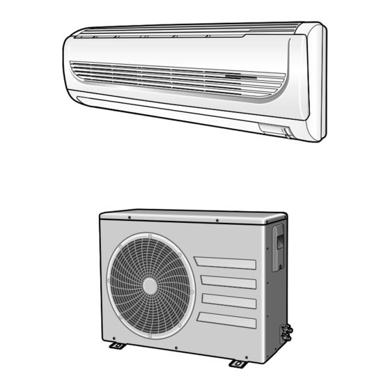
INDOOR UNIT
AQ18WJWB
AQ18WJWE
AQT18WJWB
AQT18WJWE
AQ24W6WB
AQ24W6WE
AQT24W6WB
AQT24W6WE
SH18ZWJ
SH24ZW6
Manual
CONTENTS
OUTDOOR UNIT
UQ18WJWB
UQ18WJWE
UQT18WJWB
UQT18WJWE
UQ24W6WB
UQ24W6WE
UQT24W6WB
UQT24W6WE
SH18ZWJX
SH24ZW6X
Advertisement
Table of Contents

Related Manuals for Samsung AQ18WJWB


Summary of Contents for Samsung AQ18WJWB
-
Page 1: Table Of Contents
ROOM AIR CONDITIONER INDOOR UNIT OUTDOOR UNIT AQ18WJWB UQ18WJWB AQ18WJWE UQ18WJWE AQT18WJWB UQT18WJWB AQT18WJWE UQT18WJWE AQ24W6WB UQ24W6WB AQ24W6WE UQ24W6WE AQT24W6WB UQT24W6WB AQT24W6WE UQT24W6WE SH18ZWJ SH18ZWJX SH24ZW6 SH24ZW6X Manual SERVICE AIR CONDITIONER CONTENTS 1. Product Specifications 2. Operating Instructions & Installation 3. -
Page 2: Product Specifications
1. Product Specifications 1-1 Table Model AQ18WJWB AQ24W6WB AQT18WJWB AQT24W6WB Item Indoor unit Outdoor unit Indoor unit Outdoor unit Type Wall-mounted Wall-mounted kcal/h 4,000 5,050 Cooling 18,000 24,000 BTU/h kcal/h 5,050 6,050 Heating BTU/h 20,000 24,000 Dehumidifying Cooling 13.5 14.4... - Page 3 Cooling Test Condition INDOOR UNIT : DB27˚C WB19˚C OUTDOOR UNIT : DB35˚C WB24˚C Cooling INDOOR UNIT : DB32˚C WB23˚C OUTDOOR UNIT : DB54˚C WB24˚C Maximum Operation Condition Heating INDOOR UNIT : DB27˚C WB15˚C OUTDOOR UNIT : DB24˚C WB18˚C Samsung Electronics...
-
Page 4: Pressure Graph
DB24.0 / WB17.0 DB21.0 / WB15.0 25.0 35.0 45.0 55.0 Outdoor Temp.(DB C) 24K BTU Indoor Temp.( C) DB32.4 / WB24.0 DB30.6 / WB22.5 DB27.0 / WB19.0 DB24.0 / WB17.0 DB21.0 / WB15.0 25.0 35.0 45.0 55.0 Outdoor Temp.(DB C) Samsung Electronics... -
Page 5: Operating Instructions & Installation
If you wish to save energy when using your air conditioner, select the Energy saving mode with the button. Sleep button. The sleep timer can be used when you are cooling or heating your room to switch the air conditioner off automatically after a period of 6 hours. Samsung Electronics... - Page 6 On Timer or Off Timer set. Battery life indicator. If you want to check the battery life, press the button. The longer will remain the battery life. If one battery life indicator remains, replace new batteries. Samsung Electronics...
- Page 7 ON/OFF for safety. *Deice : Deicing operation is controlled by indoor unit's heat exchanger temperature and accumulating time of compressor's operation. Deice ends by sensing of the processing time by deice condition. Samsung Electronics...
- Page 8 You can set the period of time from 1 hour to 24 hours. 11. BUZZER SOUND : Whenever the On/Off button is pressed or whenever change occurs to the condition which is set up or select, the compulsory operation mode, buzzer is sounded "beep". Samsung Electronics...
-
Page 9: Before Installation
Electric and earth work shall meet the "Electric Facility Technology Standard" and the "Internal Wire Regulation" of the Electric Business Laws. Inspection & Trial Run Upon completion of the tests, you shall make a trial run while you explain the main functions of the air conditioner to finish the installation. Samsung Electronics... -
Page 10: Installation Diagram Of Indoor Unit And Outdoor Unit
3-Way valve. And mount the service port cap to 3-Way valve. (gas) 7) Check for gas leakage. - At this time, especially check for gas leakage from the 3-Way valve’s stem nuts, (liquid) and from the service port cap. Valve stem Stem cap Samsung Electronics... - Page 11 7) Stop operation of the air conditioner. 8) Close the 3-Way valve, disconnect the pressure gauge, and open the 3-Way valve again. 9) Close the cap of each valve. Samsung Electronics...
-
Page 12: Pump Down" Procedure
• Make sure you do not bend the connection pipes in the middle and store together with the cables. • Move the indoor and outdoor units to a new location. • Remove the mounting plate for the indoor unit and move it to a new location. Samsung Electronics... -
Page 13: Disassembly And Reassembly
2) Open the Front Grille by pulling right and left sides of the hook. 3) Loosen 1 of the right screw and detach the Terminal Cover. 4) Detach the thermistor from the Front Grille. 5) Loosen 3 fixing screws of Front Grille. Samsung Electronics... - Page 14 1) Take all the connector of PCB upper side (Main PCB) out. (Inclusion Power Cord) 2) Detach the outdoor unit connection wire from the Terminal Block. 3) Loosen 4 fixing screws of Ass'y Control-In. Tray Drain 1) Pull Tray Drain out from the Back Body. Samsung Electronics...
- Page 15 5) Lifting the Heat Exchanger up a little to push the up side for separation from the indoor unit. Fan Motor 1) Loosen the fixing screw. & 2) Detach the Fan Motor from the Fan. Cross Fan 3) Detach the Fan From the left Holder Bearing. Samsung Electronics...
- Page 16 Cabinet-Side edge and a fixing screw on the Cabinet-Front lower to detach the Cabinet-Front. 3) Loosen the fixing screws of the Ass'y-Control out. 4) Loosen the fixing screws of the Cabinet-Side RH. 5) Loosen the fixing screws of the Cabinet-Side LF. Samsung Electronics...
- Page 17 1) Loosen the Terminal Cover nut to open the Compressor Terminal Cover. 2) Disassemble the cloth sound felt. 3) Disassemble the pipe in both inlet and outlet of the Compressor with welding torch. 4) Loosen the 3 bolts at the bottom. 5) Detach the Compressor. Samsung Electronics...
- Page 18 Common Work Control. 2) Loosen the fixing screws of the Cabinet-Upper. 3) Loosen the fixing screws of the Cabinet-Side RH. 4) Loosen the fixing screws of the Cabinet-Side LF. 5) Loosen the fixing screws of the Ass'y Control Out. Samsung Electronics...
- Page 19 1) Loosen the Terminal Cover to open the Terminal Cover. 2) Disassemble the Cloth Sound Felt. 3) Disassemble the pipe in both inlet and outlet of the Compressor with welding torch. 4) Loosen 3 bolts at the bottom. 5) Detach the Compressor. Samsung Electronics...
-
Page 20: Refrigerating Cycle Diagram
4-1 Refrigerating Cycle Diagram Outdoor Unit Indoor Unit Note Capillary tube Check valve 2-Way valve Liquid side Capillary tube Heat Heat Exchanger Exchanger (Evaporator) (Evaporator) Gas side 3-Way valve 4-Way valve Cooling Heating Compressor Gas Leak Check Polnt Samsung Electronics... - Page 21 45.0 55.0 Outdoor Temp.(DB C) 24K BTU Cooling Capacity Distribution 30,000 20,000 Indoor Temp.( C) DB32.4 / WB24.0 DB30.6 / WB22.5 DB27.0 / WB19.0 DB24.0 / WB17.0 DB21.0 / WB15.0 10,000 25.0 35.0 45.0 55.0 Outdoor Temp.(DB C) Samsung Electronics...
- Page 22 Heating Capacity Distribution 30,000 20,000 Indoor Temp.( C) DB25.0 DB20.0 DB15.0 10,000 1.0/0.0 7.0/6.0 20.0/15.0 Outdoor Temp.(DB/WB C) 24K BTU Heating Capacity Distribution 30,000 20,000 Indoor Temp.( C) DB25.0 DB20.0 DB15.0 10,000 1.0/0.0 7.0/6.0 20.0/15.0 Outdoor Temp.(DB/WB C) Samsung Electronics...
- Page 23 24K BTU Power consumption Distribution(Cooling mode) 4,000 3,500 3,000 2,500 Indoor Temp.( C) 2,000 DB32.4 / WB24.0 DB30.6 / WB22.5 DB27.0 / WB19.0 DB24.0 / WB17.0 1,500 DB21.0 / WB15.0 1,000 25.0 35.0 45.0 55.0 Outdoor Temp.(DB C) Samsung Electronics...
- Page 24 DB20.0 3,000 DB15.0 2,500 2,000 1,500 1,000 1.0/0.0 7.0/6.0 20.0/15.0 Outdoor Temp.(DB/WB C) 24K BTU Power consumption Distribution(Heating mode) 4,000 3,500 3,000 2,500 Indoor Temp.( C) DB25.0 2,000 DB20.0 DB15.0 1,500 1,000 1.0/0.0 7.0/6.0 20.0/15.0 Outdoor Temp.(DB/WB C) Samsung Electronics...
- Page 25 20,000 2,500 2,000 1,500 10,000 1,000 Length of Connecting Pipe(m) Length of Connecting Pipe(m) 24K BTU Power consumption(Cooling) Cooling Capacity 30,000 4,000 3,500 3,000 20,000 2,500 2,000 1,500 10,000 1,000 Length of Connecting Pipe(m) Length of Connecting Pipe(m) Samsung Electronics...
- Page 26 20,000 2,500 2,000 1,500 10,000 1,000 Length of Connecting Pipe(m) Length of Connecting Pipe(m) 24K BTU Power consumption(Heating) Heating Capacity 30,000 4,000 3,500 3,000 20,000 2,500 2,000 1,500 10,000 1,000 Length of Connecting Pipe(m) Length of Connecting Pipe(m) Samsung Electronics...
-
Page 27: Set Up The Model Option
Every time you push the button, the display panel reads . . . repeatedly. Setting Option SEG4. Push the button to set the display panel to Every time you push the button, the display panel reads . . . repeatedly. Samsung Electronics... - Page 28 Every time you push the button, the display panel reads . . . repeatedly. Setting Option SEG10. Push the button to set the display panel to Every time you push the button, the display panel reads . . . repeatedly. Samsung Electronics...
- Page 29 If all lamps of indoor unit are flickering, Plug out, plug in power plug again and press ON/OFF key to retry. If the unit is not working properly or all lamps are continuously flickering after setting the option code, see if the correct option code is set up for its model. Samsung Electronics...
- Page 30 5-2 Table of the option Code Option Code Model SEG1 SEG2 SEG3 SEG4 SEG5 SEG6 SEG7 SEG8 SEG9 SEG10 AQ18WJWB AQT18WJWB AQ18WJWE AQT18WJWE SH18ZWJ AQ24W6WB AQT24W6WB AQ24W6WE AQT24W6WE SH24ZW6 Samsung Electronics...
-
Page 31: Troubleshooting
The compressor stops intermittently or the fan speed of the The compressor stops intermittently in a COOL mode or indoor unit decreases to prevent inside/outside air frozen DRY mode, and fan speed of the indoor unit decreases. depending on the inside/outside air temperature. Samsung Electronics... - Page 32 Problem with the outdoor unit or PCB outdoor unit remote control. • In 3 minutes, check the voltage No power source Problem with the relay (RY71) or PCB between the indoor unit terminal displayed. block N1 and 1. Samsung Electronics...
- Page 33 Check whether the fuse Replace fuse on the control board is normal. F701: 3.15[A]/250[V] Check the output of SMPS on the control board. Input power: AC230±15%[V] Replace the control board IC02 Input: DC12[V] IC02 output: DC5[V] Check the setting temperature Samsung Electronics...
- Page 34 Test rod location Normal Voltage PCB CN72 Condition About AC pin #3 and #5 Fan operate 180V Replace Motor Motor Fan-Capacitor is out of order Fan-Capacitor Fan motor Fan motor is out of order. should be replaced. Samsung Electronics...
-
Page 35: When The Outdoor Unit Does Not Operate. (Initial Diagnosis)
Is rating voltage ±10% range applied relay between Power relay is Power relay should be Terminal block No. N1 and No. 1 out of order replaced. Outdoor unit is out of order. Is the room sensor normal register? 10°C 20°C 30°C 17.96kΩ 12.09kΩ 8.3kΩ Samsung Electronics... - Page 36 Voltage at pin #57~#60 Micom (IC04) is faulty. of micom (IC04) change? (Squarewave) Voltage at pin #13 ~ #16 of Driver IC06/08 (ULN2003A) is faulty. IC06(ULN2003A) change? (Squarewave) UP/DOWN louver motor is faulty. Samsung Electronics...
- Page 37 Is the voltage between Abnormal IC05 CN71 #1 and CN71 #5 rating voltage ±10% range Abnormal 4-Way valve of Outdoor Unit. Abnormal RY73 or connecting Cable PCB should be replaced. 4-Way valve should be replaced or connecting Cable Check. Samsung Electronics...
-
Page 38: Room Temperature Sensor Failure
SENSOR Resistance Value : 40˚C-5.83kΩ Connect the sensor to CN43, supply power, and measure the voltage of #1 and #2 of the CN43 connector. Poor ASS'Y PCB Replace Below 0.5V? Poor ASS'Y PCB Replace Over 4.9V? MICOM Error or Connector(CN43) check Samsung Electronics... - Page 39 When the voltage descends below 3V, the assembly module PCB is normal and the main PCB is poor. Then replace the main PCB. 3. Replace the assembly display PCB because the module PCB is poor if the voltage between No. 2~3 of CN91 maintains 5V after the remote control starts operation. Samsung Electronics...
-
Page 40: Pcb Inspection Method
2) The fan motor of the indoor unit doesn't run. • Fan Motor Connector(CN72) is faulty 3) The power voltage between terminal #3 and #5 • ASS'Y Main PCB is faulty • Connection is faulty of the connector(CN72) is 0V. Samsung Electronics... - Page 41 32.430 3.537 6.941 14.680 33.890 3.652 7.192 15.280 35.430 3.772 7.455 15.900 37.050 3.897 7.729 16.550 38.760 4.026 8.015 17.240 40.560 4.161 8.313 17.960 Temperature Sensor Characteristic Curve Temperature (˚C) At the temperature of 25˚C(10KΩ) Resistance Value (Kohm) Samsung Electronics...
-
Page 42: Main Part Inspection Method
∞, 0Ω . . . Open or Short Abnormal Stepping Motor Measure the resistance between the red wire and each terminal wire with a tester. Normal About 300Ω at the normal temperature (20˚C ~ 30˚C) ∞, 0Ω . . . Open or Short Abnormal Samsung Electronics... -
Page 43: Exploded Views And Parts List
7. Exploded Views and Parts List 7-1 Indoor Unit You can search for the updated part code number through the ITSELF. URL : http://itself.sec.samsung.co.kr Samsung Electronics... - Page 44 Exploded Views and Parts List Parts List Q'TY Code No. Description Specification AQ18WJWB AQT18WJWB AQ24W6WB AQ18WJWE AQT18WJWE AQ24W6WE DB94-00615A ASS'Y BACK BODY ASS'Y DB61-01974A BODY BACK HIPS DB69-01039A CUSHION-BACK BODY FO-PS DB96-03913A ASS'Y CYCLE IN ASS'Y DB96-03809A ASS'Y CYCLE IN...
- Page 45 DB61-01981A HOLDER-PIPE HIPS DB63-01063A COVER-CONTROL HIPS DB93-02532B ASS'Y REMOCON ASS'Y DB96-03817A ASS'Y EVAP-SUPPORT ASS'Y DB31-00267A MOTOR FAN YFK 40 4C DB94-00456B ASS'Y-CROSS FAN ASS'Y DB97-02075A ASS'Y-BOLT SPECIAL M5xL6 DB73-00181A RUBBER-BEARING RUBBER DB94-40007A ASS'Y BEARING-MOTOR ASS'Y DB61-01977A BRACKET-EVAP SGCC-M Samsung Electronics...
- Page 46 MEMO Samsung Electronics...
- Page 47 7-2 Outdoor Unit 18K BTU 14-2 14-1 14-3 14-4 Samsung Electronics...
- Page 48 48B200JT1EH-SS ROTARY COMPRESSOR ASS'Y 48D190IT1EH-SS ROTARY COMPRESSOR ASS'Y DB96-03873A ASS'Y COND ASS'Y DB62-03032A INSULATION-SOUND FELT DB99-00567A ASS'Y VALVE CHECK ASS'Y DB99-00567B ASS'Y VALVE CHECK ASS'Y DB99-00566A ASS'Y VALVE 4WAY ASS'Y DB99-00566B ASS'Y VALVE 4WAY ASS'Y DB71-00093A BAR-STEEL HSWR Samsung Electronics...
- Page 49 Exploded Views and Parts List 24K BTU 15-4 15-3 15-1 15-2 Samsung Electronics...
- Page 50 ASS'Y CONTROL OUT ASS'Y DB93-03236D ASS'Y CONTROL OUT ASS'Y 15-1 3501-000305 RELAY EL200/240A1-F 15-2 2501-001239 C-OIL 45uF/450VAC 2501-001240 C-OIL 50uF/450VAC 15-3 DB65-00164A TERMINAL BLOCK 15-4 2301-001379 C-FILM 4uF/450VAC DB72-00630C INSULATION-SOUND FELT DB90-01351A ASS'Y CABINET-LF ASS'Y DB71-00088A BAR-STEEL MSWR Samsung Electronics...
- Page 51 ASS'Y-S/W & DISPLAY PCB ASS'Y DB70-00507A PLATE-TERMINAL LOW SGCC-M, T1.2 DB61-01980A HOLDER-WIRE CLAMP 6001-000929 SCREW-MACHINE PH M3xL22 6001-001054 SCREW-MACHINE TH M4xL10 DB39-01046A ASS'Y-C/W DISPLAY PCB ASS'Y DB39-00147A C/W STEP MOTOR UP/DOWN ASS'Y DB32-00020D ASS'Y-THERMISTOR 4P(103AT) DB63-00851A COVER LAMP Samsung Electronics...
-
Page 52: Block Diagram
STEPPING MOTOR • 4-WAY VALVE DRIVE(*) : BLADE UP/DOWN ON, OFF TIMER SELECT TEMPERATURE DC5V SELECT VOLTAGE REGULATOR SLEEP SELECT DC12V ENERGY SAVING SMPS POWER BLOCK BATTERY CHECK AC INPUT (*)marks : In case of heat pump model. Samsung Electronics... -
Page 53: Wiring Diagram
9. Wiring Diagram 9-1 Indoor Unit 18K BTU Code No : DB68-02811A This Document can not be used without Samsung's authorization. Samsung Electronics... - Page 54 Wiring Diagram 24K BTU Code No : DB98-20290A This Document can not be used without Samsung's authorization. Samsung Electronics...
-
Page 55: 24K Btu
9-2 Outdoor Unit 18K BTU MARK NAME MARK NAME SOLENOID COIL FAN MOTOR Code No : DB68-02812A 24K BTU MARK NAME MARK NAME SOLENOID COIL FAN MOTOR Code No : DB98-20291A This Document can not be used without Samsung's authorization. Samsung Electronics... - Page 56 MEMO Samsung Electronics...
- Page 57 MEMO Samsung Electronics...
- Page 58 ELECTRONICS This Service Manual is a property of Samsung Electronics Co., Ltd. © Samsung Electronics Co., Ltd. Jan. 2005. Any unauthorized use of Manual can be punished under applicable Printed in Korea. International and/or domestic law. Code No. DB98-20874A(1)