Comtech EF Data SLM-5650A Installation And Operation Manual
Satellite modem
Hide thumbs
Also See for SLM-5650A:
- User manual (154 pages) ,
- Installation and operation manual (516 pages)
Table of Contents
Advertisement
Quick Links
Advertisement
Chapters
Table of Contents

Related Manuals for Comtech EF Data SLM-5650A


Summary of Contents for Comtech EF Data SLM-5650A
-
Page 1: Installation And Operation Manual
SLM-5650A Satellite Modem Installation and Operation Manual IMPORTANT NOTE: The information contained in this document supersedes all previously published information regarding this product. This manual is subject to change without prior notice. Part Number MN-SLM5650A Revision 8... - Page 3 Errata A Comtech EF Data Documentation Update Subject: Revise to include extended temperature information for Network Processor option Original Manual Part Number/Rev: MN‐SLM5650A Rev 8 Errata Number/ PLM Document ID: ER‐SLM5650A‐EA8 PLM CO Number: C‐0027953 Comments: Updated Sections: 1.3.3.3.1 Network Processor FAST Accessible Options D.10 Extended Temperature Option Revised pages follow. ER-SLM5650A-EA8 THIS DOCUMENT IS NOT SUBJECT TO REVISION/UPDATE! PLM CO C-0027953...
- Page 4 ER-SLM5650A-EA8 THIS DOCUMENT IS NOT SUBJECT TO REVISION/UPDATE! PLM CO C-0027953 Page 2 of 4...
- Page 5 ER-SLM5650A-EA8 THIS DOCUMENT IS NOT SUBJECT TO REVISION/UPDATE! PLM CO C-0027953 Page 3 of 4...
- Page 6 ER-SLM5650A-EA8 THIS DOCUMENT IS NOT SUBJECT TO REVISION/UPDATE! PLM CO C-0027953 Page 4 of 4...
- Page 7 Errata B Comtech EF Data Documentation Update Subject: Revise to include extended temperature information for Network Processor option Original Manual Part Number/Rev: MN‐SLM5650A Rev 8 Errata Number/ PLM Document ID: ER‐SLM5650A‐EB8 PLM CO Number: C‐0028075 Comments: Updated page C‐41: Router Ethernet Interface Traffic IP Address and Range command, corrected typo Revised pages follow. ER-SLM5650A-EB8 This document is not subject to revision/update!
- Page 8 ER-SLM5650A-EB8 This document is not subject to revision/update! CO C-0028075 Revision - Page 2 of 2...
- Page 9 SLM-5650A Satellite Modem Installation and Operation Manual Part Number MN-SLM5650A Revision 8 Copyright © 2013 Comtech EF Data. All rights reserved. Printed in the USA. Comtech EF Data, 2114 West 7th Street, Tempe, Arizona 85281 USA, 480.333.2200, FAX: 480.333.2161...
- Page 10 BLANK PAGE...
-
Page 11: Table Of Contents
Operating Environment ............................xxiii European Union Radio Equipment and Telecommunications Terminal Equipment (R&TTE) Directive (1999/5/EC) and EN 301 489-1 ..............................xxiii Contact Comtech EF Data ..........................xxv Warranty Policy ............................. xxvi Limitations of Warranty ............................xxvi Exclusive Remedies .............................. xxvi CHAPTER 1. - Page 12 SLM-5650A Satellite Modem Revision 8 Table of Contents MN-SLM5650A Connect External Cables ........................2–7 Configuration ............................2–7 CHAPTER 3. REAR PANEL CONNECTORS A ND PINOUTS ..........3–1 Overview ............................3–1 IF Connectors ............................3–3 3.2.1 J2, J4 L-Band IF Interface Connectors ....................... 3–3 3.2.2...
- Page 13 7.2.2 User Login..............................7–2 7.2.3 HTTP Interface – Operational Features ....................7–3 7.2.4 HTTP Interface Menu Tree ........................7–4 SLM-5650A Base Modem HTTP Interface Page Descriptions ..............7–5 7.3.1 Home pages.............................. 7–5 7.3.2 Admin pages ............................. 7–8 7.3.3 Config Mdm (Modem Configuration) pages ..................7–10 7.3.4...
- Page 14 SLM-5650A Satellite Modem Revision 8 Table of Contents MN-SLM5650A Interface Specifications ........................8–3 8.3.1 Physical Description ..........................8–3 8.3.2 General Specifications ..........................8–3 NP Interface Module Removal and Installation ..................8–4 8.4.1 NP Interface Module Removal Procedure....................8–4 8.4.2 NP Interface Module Installation Procedure ................... 8–4 BPM (Bridge Point-to-Multipoint) Mode .....................
- Page 15 11.2.6 Event Log [E] ............................ 11–14 11.2.7 Unit Info [ I ] ............................. 11–15 11.2.8 Comtech EF Data Information page [Z] ................... 11–16 CHAPTER 12. 10/100/1000 BASET (GBE) INTERFACE ..........12–1 12.1 Introduction ............................. 12–1 12.2 Physical Description .......................... 12–1 12.2.1...
- Page 16 SLM-5650A Satellite Modem Revision 8 Table of Contents MN-SLM5650A 14.2.1 “J1” Connector Pinout ........................14–3 14.3 General Specifications ........................14–4 14.4 LVDS Interface Module Removal and Installation ................... 14–5 14.4.1 LVDS Interface Module Removal Procedure ..................14–5 14.4.2 LVDS Interface Module Installation Procedure .................. 14–5 CHAPTER 15.
- Page 17 SLM-5650A Satellite Modem Revision 8 Table of Contents MN-SLM5650A APPENDIX B. OPERATIONS REFERENCE ................B–1 Overview ............................B–1 Modes ..............................B–1 B.2.1 OM-73 Mode ............................B–1 B.2.2 MIL-STD-188-165A Mode ........................B–2 B.2.3 MIL-STD-188-165A Mode – Sequential ....................B–3 B.2.4 IESS-308 Mode – Standard Higher Rates ....................B–4 B.2.5...
- Page 18 SLM-5650A Satellite Modem Revision 8 Table of Contents MN-SLM5650A C.6.4 Modem, Unit Commands / Queries ...................... C–21 C.6.5 Bulk Configuration Commands / Queries ....................C–29 C.6.6 Automatic Uplink Power Control (AUPC) Commands / Queries ............C–32 C.6.7 G.703 Interface Commands / Queries ....................C–37 C.6.8...
- Page 19 Figure 1-4. SLM-5650A Front Panel View ....................1–5 Figure 1-5. SLM-5650A Rear Panel View ....................1–5 Figure 2-1. Unpacking and Inspecting the SLM-5650A ................2–1 Figure 2-2. SLM-5650A Rack Enclosure Installation Example ..............2–3 Figure 2-3. Optional Rear Support Bracket Installation ................2–5 Figure 2-4.
- Page 20 SLM-5650A Satellite Modem Revision 8 Table of Contents MN-SLM5650A Figure 7-8. Config Mdm | Modem Utilities (Page 3) ................7–12 Figure 7-9. Config Mdm | Spreading page ....................7–13 Figure 7-10. Config Mdm | Automatic Uplink Power Control page ............7–14 Figure 7-11.
- Page 21 Figure 14-2. LVDS Interface Functional Block Diagram ................. 14–2 Figure 155-1. Conceptual Block Diagram ....................15–3 Figure 15-2. Conventional FDMA Link ....................15–5 Figure 15-3. Same Link Using SLM-5650A and DoubleTalk Carrier-in-Carrier ........15–6 Figure 15-4. Duplex Link Optimization ....................15–6 Figure 15-5. DoubleTalk Carrier-in-Carrier Signals ................15–8 Figure 15-6.
- Page 22 SLM-5650A Satellite Modem Revision 8 Table of Contents MN-SLM5650A BLANK PAGE...
-
Page 23: Preface
PREFACE About this Manual This manual describes the installation and operation for the Comtech EF Data SLM-5650A Satellite Modem. This is a document intended for the persons responsible for the operation and maintenance of the SLM-5650A. Conventions and References Patents and Trademarks See all of Comtech EF Data's Patents and Patents Pending at http://patents.comtechefdata.com. -
Page 24: Warnings, Cautions, And Notes
Safety and Compliance Electrical Safety and Compliance The SLM-5650A complies with the EN 60950 Safety of Information Technology Equipment (Including Electrical Business Machines) safety standard. If the unit is operated in a vehicle or movable installation, make sure the unit is stable. -
Page 25: Electrical Installation
SLM-5650A Satellite Modem Revision 8 Preface MN-SLM5650A Electrical Installation Connect the unit to a power system that has separate ground, line and neutral conductors. Do not connect the unit without a direct connection to ground. Operating Environment Do not operate the unit in any of these extreme operating conditions: Ambient temperatures less than 0°... - Page 26 In accordance with the European Union Telecommunications Terminal Equipment Directive 91/263/EEC, the unit should not be directly connected to the Public Telecommunications Network. CE Mark Comtech EF Data declares that the unit meets the necessary requirements for the CE Mark. xxiv...
-
Page 27: Contact Comtech Ef Data
Revision 8 Preface MN-SLM5650A Contact Comtech EF Data Contact Comtech EF Data during normal business hours: Monday through Friday, 8 A.M. to 5 P.M Mountain Standard Time (MST) Be prepared to provide the product model and serial numbers. For: Contact: Telephone +1.480.333.4357... -
Page 28: Warranty Policy
In most cases, the warranty period is two years. During the warranty period, Comtech EF Data will, at its option, repair or replace products that prove to be defective. Repairs are warranted for the remainder of the original warranty or a 90 day extended warranty, whichever is longer. -
Page 29: Chapter 1. Introduction
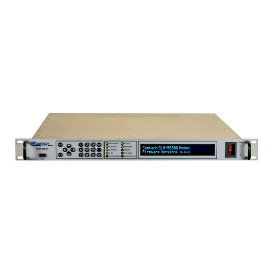
Chapter 1. INTRODUCTION Overview Figure 1-1. SLM-5650A Satellite Modem The SLM-5650A Satellite Modem (Figure 1-1) satisfies the requirements for government and military communications system applications that require state-of-the-art modulation and coding techniques to optimize satellite transponder bandwidth usage, while retaining backward compatibility. -
Page 30: Functional Description
Functional Description Figure 1-2. SLM-5650A Block Diagram Figure 1-2 depicts the functional block diagram for the SLM-5650A. The modem has been designed to accommodate a wide range of currently required features, and to support both near- and far-term advances in software-defined radio technology as well as advances in FEC technology. -
Page 31: Slm-5650A Features
SLM-5650A Satellite Modem Revision 8 Introduction MN-SLM5650AMN-SLM5650A SLM-5650A Features The SLM-5650A incorporates the following features: • MIL-STD-188-165A compliance (Types A, B, D, E, F); • Intelsat IESS-308, -309, -310, and -315; • A rugged, one-rack unit (1RU) enclosure; • Low weight and low power dissipation;... -
Page 32: Physical Description
Introduction MN-SLM5650AMN-SLM5650A 1.3.1 Physical Description The SLM-5650A is constructed as a 1RU high, rack-mount chassis that can be free-standing as needed. Handles at the front ease removal from and placement into a rack. 1.3.1.1 Dimensional Envelope Figure 1-3. SLM-5650A Dimensional Envelope... -
Page 33: Physical Features
Eases installation into / removal from rack Figure 1-4. SLM-5650A Front Panel View Local control of the SLM-5650A is accomplished from the modem’s front panel (Figure 1-4). The function and behavior of the keypad/data entry array, LED Indicators, and VFD are described in detail in Chapter 5. -
Page 34: Operational Features
(as specified under IAW IESS-308, IESS-309, and IESS-310 requirements for open network operation). A Comtech EF Data overhead channel is provided so that the modem is capable of operating in such closed networks over commercial satellites IAW Intelsat requirements for use during closed network operation. -
Page 35: Data Interfaces
1.3.3.3 Data Interfaces The SLM-5650A supports only one data interface at a time. The modem features two native data interfaces (TIA/EIA-530/422 and TIA/EIA-613 [HSSI]), plus an option slot for installation of a modular data interface. The optional modular interfaces available at this time are the Network Processor, Gigabit Ethernet, G.703, and LVDS. -
Page 36: Independent Tx And Rx Function
1.544, 2.048, 6.312, and 8.448 Mps as defined by ITU-T G.703. 1.3.3.3.4 LVDS The optional Low Voltage Differential (LVDS) interface provides a physical and electrical interface between an SLM-5650A modulator and demodulator and signal sources operating with LVDS electrical characteristics. 1.3.3.3.5 TIA/EIA-530 The native TIA/EIA-530 interface supports the physical layer requirements for TIA/EIA-530. -
Page 37: Updating Modem Firmware
If, at a later date, the user wishes to upgrade the functionality of a unit, Comtech EF Data provides Fully Accessible System Topology (FAST), a technology which permits the purchase and installation of options through special authorization codes. -
Page 38: Fast Accessible Options
MN-SLM5650AMN-SLM5650A FAST Accessible Options SLM-5650A hardware options can be ordered and installed either at the factory or in the field. In the field, the operator can select options that can be easily activated, depending on the current hardware configuration of the unit. The unique FAST Access Code that is purchased from Comtech EF Data enables configuration of the available hardware. -
Page 39: Interoperability
Revision 8 Introduction MN-SLM5650AMN-SLM5650A 1.3.4 Interoperability 1.3.4.1 Legacy Modems The SLM-5650A is fully compatible and interoperable with all specified modes of operation of the following legacy modems: • OM-73 (V); • MD-1352 (P)/U (BEM-7650); • MD-1340 (OM-73 interoperable mode only; orderwire not required);... -
Page 40: Summary Of Specifications
SLM-5650A Satellite Modem Revision 8 Introduction MN-SLM5650AMN-SLM5650A Summary of Specifications General Specifications Parameter Specifications Operating Frequency Range 52 to 88, 104 to 176, 950 to 2000 MHz ( in 100 Hz steps). Modulation Types BPSK, QPSK, OQPSK, 8PSK, 8QAM, 16QAM. - Page 41 SLM-5650A Satellite Modem Revision 8 Introduction MN-SLM5650AMN-SLM5650A Demodulator Specifications Parameter Specifications For 70/140 MHz: +10 to -55 dBm +10 to -55 dBm (SR>3.2 MSPS) Desired Carrier Input For L-Band: +10 to 10·log (SR/32000) -75 dBM Power (SR≤3.2 MSPS) where SR is in symbols per second...
-
Page 42: Performance
SLM-5650A Satellite Modem Revision 8 Introduction MN-SLM5650AMN-SLM5650A 1.4.1 Performance 1.4.1.1 Acquisition and Timing Performance Requirements The following reference E is defined as the required E corresponding to a BER of IE-3 with Reed-Solomon FEC not enabled. Table 1-1. Acquisition and Timing Performance Requirements... -
Page 43: Data Quality Performance
IESS-310. 1.4.1.2.6 16QAM Coding Mode Performance The SLM-5650A operating in the 16QAM mode provides back-to-back BER vs. E performance better than or equal to the values shown in Table 1-7 when using the modulation formats indicated. 1–15... -
Page 44: Turbo Coding Mode Performance
Introduction MN-SLM5650AMN-SLM5650A 1.4.1.2.7 Turbo Coding Mode Performance The SLM-5650A operating in the Turbo Code Mode provides back-to-back BER vs. E performance better than or equal to the values shown in Table 1-8 when using the modulation formats indicated. 1.4.1.2.8 Sequential Mode Performance The SLM-5650A operating in the Sequential Mode provides back-to-back BER vs. -
Page 45: Table 1-3. Viterbi Decoder Ber
SLM-5650A Satellite Modem Revision 8 Introduction MN-SLM5650AMN-SLM5650A 1.4.1.3 BER Performance 1.4.1.3.1 BPSK/QPSK/Offset QPSK, Viterbi Decoding Table 1-3. Viterbi Decoder BER (dB) Specifications Viterbi Decoder Uncoded 10.8 11.6 12.4 13.0 1.4.1.3.2 BPSK/QPSK/Offset QPSK, Viterbi Decoding and Reed-Solomon Table 1-4. BSPK/QPSK/OQPSK Viterbi with Reed-Solomon Decoder BER Performance... -
Page 46: Table 1-6. 8Psk, Trellis Decoder With Reed-Solomon Ber Performance
SLM-5650A Satellite Modem Revision 8 Introduction MN-SLM5650AMN-SLM5650A 1.4.1.3.4 8PSK, Trellis Decoder and Reed-Solomon Table 1-6. 8PSK, Trellis Decoder with Reed-Solomon BER Performance (dB) Specifications Trellis Decoder with Reed-Solomon 1.4.1.3.5 16QAM, Viterbi Decoder and Reed-Solomon Table 1-7. 16QAM, Viterbi Decoder with Reed-Solomon BER Performance... -
Page 47: Table 1-9. Sequential Decoding With / Without Reed-Solomon Ber Performance
SLM-5650A Satellite Modem Revision 8 Introduction MN-SLM5650AMN-SLM5650A 1.4.1.3.7 Sequential Decoding with / without Reed-Solomon Table 1-9. Sequential Decoding with / without Reed-Solomon BER Performance (dB) Specifications Sequential Decoder with / without Reed-Solomon BPSK QPSK/OQPSK DESCRIPTION Sequential – 64 kbps Sequential – 1544 kbps Sequential+RS (225,205) 1.4.1.3.8... -
Page 48: Table 1-10. Acceptable Aci Degradation With Spacing Factor Of 1.2
SLM-5650A Satellite Modem Revision 8 Introduction MN-SLM5650AMN-SLM5650A 1.4.1.3.9 BER Performance with Asymmetrical Adjacent Carriers Operating in the presence of two adjacent asymmetrical carriers, one lower in frequency and one higher in frequency, and each adjacent carrier symbol rate (R" ) = 2.0 R' , the modem performance is not degraded more than indicated in Table 1-10 Column 4, and a) and b) in this section. - Page 49 SLM-5650A Satellite Modem Revision 8 Introduction MN-SLM5650AMN-SLM5650A 1.4.1.3.11 LDPC LL Decoding Table 1-12. LDPC LL Decoder BER Performance E b /N 0 (dB) Specification BPSK QPSK 8QAM 16QAM .382 .456 .547 1.4.1.3.12 LDPC HP Decoding Table 1-13. LDPC HP Decoder BER Performance...
- Page 50 SLM-5650A Satellite Modem Revision 8 Introduction MN-SLM5650AMN-SLM5650A BLANK PAGE 1–22...
-
Page 51: Chapter 2. Installation
Chapter 2. INSTALLATION Unpacking and Inspection The SLM-5650A Satellite Modem, its Installation and Operation Manual, and its power cord were packaged and shipped in a reusable cardboard carton containing protective foam spacing. Figure 2-1. Unpacking and Inspecting the SLM-5650A 2–1... -
Page 52: Installation
Check the packing list to ensure the shipment is complete. Inspect the equipment for any possible damage incurred during shipment. Contact the carrier and Comtech EF Data immediately and submit a damage report if damage is evident to the shipment. -
Page 53: Figure 2-2. Slm-5650A Rack Enclosure Installation Example
Revision 8 Installation MN-SLM5650A Figure 2-2. SLM-5650A Rack Enclosure Installation Example Install the SLM-5650A in its assigned position in the rack enclosure. Use, as required: • A standard rack-mounted shelf; • User-supplied screws to secure the front panel to the rack enclosure threaded front rails;... -
Page 54: Installing The Optional Rear Support Brackets Kit
SLM-5650A Satellite Modem Revision 8 Installation MN-SLM5650A 2.2.1 Installing the Optional Rear Support Brackets Kit Tools needed to install the KT/6228 (4”) or KT/6228 (10”) Bracket Kit: A medium Phillips screwdriver • • A 5/32-inch SAE Allen Wrench • An adjustable Crescent wrench. -
Page 55: Figure 2-3. Optional Rear Support Bracket Installation
SLM-5650A Satellite Modem Revision 8 Installation MN-SLM5650A Detail Description Back of modem Rack Enclosure Rear Rail (typical) Kit / Quantity Item Part Number Description KT/6228-2 KT/6228-3 HW/10-32SHLDR Shoulder Screw, #10 HW/10-32FLT Flat Washer, #10 HW/10-32SPLIT Lock Washer, #10 HW/10-32HEXNUT Hex Nut, #10... -
Page 56: Installing The Optional Bearingless Rack Slide Set
2.2.2 Installing the Optional Bearingless Rack Slide Set The optional FP/SL0006 Bearingless Rack Slide Set may be installed into the equipment rack cabinet and onto the sides of the SLM-5650A as shown in Figure 2-4 and per the following procedure:... -
Page 57: Connect External Cables
SLM-5650A Satellite Modem Revision 8 Installation MN-SLM5650A Connect External Cables Connect the cables to the proper locations on the rear panel. See Chapter 3. REAR PANEL CONNECTORS PINOUTS. Configuration All configurations are implemented locally via the unit’s loaded firmware. Step Task Read Chapter 5. - Page 58 SLM-5650A Satellite Modem Revision 8 Installation MN-SLM5650A BLANK PAGE 2–8...
-
Page 59: Chapter 3. Rear Panel Connectors A Nd Pinouts
PINOUTS A ND Overview The SLM-5650A rear panel connectors (Figure 3-1) provide all necessary external connections between the modem and other equipment. Table 3-1 on the next page summarizes the connectors provided here, grouped according to service function. Figure 3-1. SLM-5650A Rear Panel... -
Page 60: Table 3-1. Slm-5650A Rear Panel Connectors
To maintain compliance with the European EMC Directive 2004/108/EEC (EN 55022, EN- 55024), properly shielded cables are required for all data I/O. The ‘D-Shell’ connectors (J6, J8, J9, J10, P1) provided on the SLM-5650A rear panel feature threaded nuts to ensure the mechanical integrity of the mated connections. -
Page 61: If Connectors
SLM-5650A Satellite Modem Revision 8 Rear Panel Connectors and Pinouts MN-SLM5650A IF Connectors 3.2.1 J2, J4 L-Band IF Interface Connectors The L-Band IF Interfaces use standard 50 Ω Type ‘N’ female connectors: Type ‘N’ Connector Ref Des Description Direction 950-2000 MHz Transmit... -
Page 62: P1 Overhead Data Interface Connector (Db-25M)
SLM-5650A Satellite Modem Revision 8 Rear Panel Connectors and Pinouts MN-SLM5650A 3.3.2 P1 Overhead Data Interface Connector (DB-25M) This is a male Type ‘D’ 25-pin ‘D’ (DB-25M) connector that allows for connection of the EIA-422, EIA-485 and EIA-232 data interfaces used with overhead framing. -
Page 63: J6 Eia-530 Connector (Db-25F)
SLM-5650A Satellite Modem Revision 8 Rear Panel Connectors and Pinouts MN-SLM5650A 3.3.3 J6 EIA-530 Connector (DB-25F) This is a female Type ‘D’ 25-pin (DB-25F) connector that conforms to the EIA-530 pinout for EIA-422 operation only. J6 EIA-530 Connector (DB-25F) Pinout... -
Page 64: J7 Hssi Connector
SLM-5650A Satellite Modem Revision 8 Rear Panel Connectors and Pinouts MN-SLM5650A 3.3.4 J7 HSSI Connector Pin # Name Ground Ground Notes: 1. 50-pin female connector. 2. These are non-HSSI defined signals. Not Used On Cisco routers there is no connection Not Used to those pins. -
Page 65: Interface Option Slot
SLM-5650A Satellite Modem Revision 8 Rear Panel Connectors and Pinouts MN-SLM5650A 3.3.5 Interface Option Slot You can install optional data interfaces into the unit’s interface option slot. Read these chapters for more information about the optional data interfaces: Network Processor... -
Page 66: J9 Auxiliary Connector (Hd-15F)
SLM-5650A Satellite Modem Revision 8 Rear Panel Connectors and Pinouts MN-SLM5650A 3.4.3 J9 Auxiliary Connector (HD-15F) This is a female type ‘HD’ 15-pin (HD-15F) connector that provides TTL open collector faults for the modulator and demodulator; a TTL input for external transmit carrier mute;... -
Page 67: Power/Ground Connectors
SLM-5650A Satellite Modem Revision 8 Rear Panel Connectors and Pinouts MN-SLM5650A Power/Ground Connectors 3.5.1 AC Power Connector A standard, detachable, non-locking, 3-prong power cord (IEC plug) supplies the Alternating Current (AC) power to the modem. Note the following: Input Power... - Page 68 SLM-5650A Satellite Modem Revision 8 Rear Panel Connectors and Pinouts MN-SLM5650A BLANK PAGE 3–10...
-
Page 69: Chapter 4. Updating Firmware
The SLM-5650A is factory-shipped with the latest version of operating firmware. If a firmware update is needed, it can be acquired by download from Comtech EF Data’s Web site (Figure 4-1) or from Comtech EF Data Customer Support during normal business hours via e-mail or on CD by standard mail delivery. -
Page 70: Figure 4-1. Firmware Update Via Internet
To obtain the firmware update for the TRANSEC Module, contact Network Product Customer Support. The firmware download files are available from Comtech EF Data in two archive file formats: *.exe (self extracting) and *.zip (compressed). Some firewalls will not allow the downloading of *.exe files;... -
Page 71: Bulk Firmware Update - Ethernet Ftp Upload Procedure
– see Step 1); revision letter and, if applicable; the release version number. The base modem bulk firmware for the SLM-5650A is FW-0000030x (where the ‘x’ denotes the revision letter of the bulk modem firmware). The current version firmware release is provided. If applicable, one version prior to the current release is also available. - Page 72 SLM-5650A Satellite Modem Revision 8 Updating Firmware MN-SLM5650A Step Task Extract the files to the temporary folder on the PC. A minimum of two files should be extracted: Fw-0000030x.bin, where "x" denotes the revision letter for the bulk image file.
-
Page 73: Network Processor (Np) Interface Module Update Procedure
SLM-5650A Satellite Modem Revision 8 Updating Firmware MN-SLM5650A Network Processor (NP) Interface Module Update Procedure Step Task Identify the firmware number and version for download, as was done in Chapter Sect. 4.2 Step 1 (Bulk Firmware Update). Note: To aid identification, when using the NP HTTP/HTTPS Interface the Bootrom, Image 1, and Image 2 firmware loads may be viewed after selecting the Upgrade hyperlink available from the Admin (Administration) page. - Page 74 ‘xxx.xxx.xxx.xxx’ is the NP Module’s IP address). The results should confirm whether or not the module is connected and communicating. Initiate a Web session with the SLM-5650A’s NP Module using the PC and a supported Web browser. Note the following: The browser and page examples that follow use Internet Explorer Version 7.0.
- Page 75 SLM-5650A Satellite Modem Revision 8 Updating Firmware MN-SLM5650A Step Task To update the Network Processor Bulk firmware: Open the Admin | Upgrade page: In the Upgrade section of the page, locate the update file downloaded to the PC during Steps 2 through 4: Click [Browse].
- Page 76 SLM-5650A Satellite Modem Revision 8 Updating Firmware MN-SLM5650A Step Task Upon successful completion of transfer, the progress bar reads 100%, and the Image Upgrade Complete message (cont) displays: Click [OK] to exit the Image Upgrade page and return to the Admin | Upgrade page.
- Page 77 SLM-5650A Satellite Modem Revision 8 Updating Firmware MN-SLM5650A Step Task After saving, return to the Admin | Reboot page, then click [Reboot Now] to boot the NP Module with the new firmware: To load the second image, repeat Steps 10 through 12.
-
Page 78: Transec Module Update Procedure
Firmware updates for the TRANSEC Module (also referred to in front panel menu screens as the “Option Card”) are not available from the Comtech EF Data Web site, but they may be obtained from Comtech EF Data on an as-needed basis. To obtain these updates, contact Comtech EF Data Customer Support to request access to the modem firmware update files online FTP site. - Page 79 ‘xxx.xxx.xxx.xxx’ is the TRANSEC Module’s IP address). The results should confirm whether or not the module is connected and communicating. Initiate a secure Web session with the SLM-5650A’s TRANSEC Module via its HTTPS Interface. The example uses Internet Explorer Version 7.0.
- Page 80 SLM-5650A Satellite Modem Revision 8 Updating Firmware MN-SLM5650A Step Task Wait while the file transfers. After [Upload] is clicked, the Firmware Application Process page appears while the TRANSEC Module transfers then uploads the update file from the PC. Allow sufficient time for the file to be uploaded – approximately five minutes is required for the process to be completed.
- Page 81 SLM-5650A Satellite Modem Revision 8 Updating Firmware MN-SLM5650A Step Task Upon successful completion of transfer, the progress bar reads 100%, and the Firmware Application Process (cont) Complete! message displays: On the Admin | Update Firmware page, verify that the newly-uploaded firmware is reported in the proper Security Module Bulk Info slot.
- Page 82 Click [Reboot Now!] to boot the TRANSEC Module with the new firmware: The modem will reboot with the new firmware loaded as configured: It will be necessary to restart the SLM-5650A’s TRANSEC Module HTTPS Interface session once the modem has returned online.
-
Page 83: Overview
Chapter 5. FRONT PANEL OPERATION Overview The SLM-5650A Satellite Modem front panel (Figure 5-1) allows the user to monitor the modem operating status (including clocking information) and to control modem configuration parameters. Item Description Function USB Port Reserved for future software support... -
Page 84: Chapter 5. Front Panel Operation
SLM-5650A Satellite Modem Revision 8 Front Panel Operation MN-SLM5650A 5.1.1 Keypad with Data Entry Array The front panel keypad controls the local operation of the modem. This control section consists of 18 buttons (keys). Each key provides one or more logical functions. -
Page 85: Led Indicators
SLM-5650A Satellite Modem Revision 8 Front Panel Operation MN-SLM5650A 5.1.2 LED Indicators The 10 LEDs on the front panel indicate: General modem summary fault information; • • Status; • Alarms. The behavior of the individual front panel LED indicators is as follows:... -
Page 86: Vacuum Fluorescent Display (Vfd)
To prevent such burn-in, a screen saver feature activates after 15 minutes. The screen saver messages loop from right to left across the screen. Sandwiched between the product display message “Comtech EF Data SLM-5650A Modem” and the user prompt “Press any key to continue”, the following operating statistics are provided:... -
Page 87: Select: (Main) Menu
Opening Screen The front panel menu screens provide the visual means to fully control and monitor operation of the SLM-5650A. The first screen to display, after the modem power switch is turned on, is the read-only opening screen: Comtech SLM-5650A Modem State: Firmware Version x.x.x... -
Page 88: Select (Main) Menu Matrix
SLM-5650A Satellite Modem Revision 8 Front Panel Operation MN-SLM5650A 5.2.1 SELECT (Main) Menu Matrix Menu Branch Para Nested Menu Sect Selectable Submenus Configure 5.2.2 Mod, DataRate, Overhead, Frequency, Power, Clocking, Misc, Spreading Demod, DataRate, Overhead, Frequency, 5.2.3.2 Acquisition, Buffer, Misc, CnC, Spreading Mode 5.2.3.3... -
Page 89: Navigating The Menu Screens
SLM-5650A Satellite Modem Revision 8 Front Panel Operation MN-SLM5650A 5.2.2 Navigating the Menu Screens Both single-function and multi-function menu screens are used throughout the front panel SELECT: menu interface. Both screen types display all available options and prompt the user to carry out a required action. -
Page 90: Select: Configure
AUPC. Transec Select to configure the TRANSEC Module operation. Select to configure the Antenna Handover parameters (when the SLM-5650A is used with the AntHndOvr CRS-311-AH Antenna Handover Switch). This menu is selectable only if the Antenna Handover FAST option is installed. - Page 91 SLM-5650A Satellite Modem Revision 8 Front Panel Operation MN-SLM5650A 5.2.3.1 CONFIG: Tx Tx: Mod DataRate Overhead Frequency Power Clocking Misc Spreading (E) Use the arrow keys to select a Tx configuration submenu, and then press [ENT]: Submenu Option Select: FEC, Type, Rate, RS, Diff, and Scrambler.
- Page 92 Scrambling (for energy dispersal): V.35, MOD-V.35, IBS, TURBO, OM73, Synch, or Off. Note the following: V.35 – ITU standard. • MOD-V.35 (Modified V.35) – Comtech EF Data Closed Network with Reed- Solomon • compatible . IBS – Used for IESS-309 operation.
- Page 93 SLM-5650A Satellite Modem Revision 8 Front Panel Operation MN-SLM5650A CONFIG: Tx Overhead Overhead:None Rate: N/A RS-CW:N/A Depth:N/A (E) First, use the arrow keys to select Overhead, Rate, RS-CW, and Depth, and then press [ENT]. Then, use the arrow keys to scroll through the available settings. Press [ENT] once again when done.
- Page 94 SLM-5650A Satellite Modem Revision 8 Front Panel Operation MN-SLM5650A CONFIG: Tx Power Tx Power: State:On Level:-20.0 Control: Normal (E) First, use the arrow keys to select State, Level, or Control, and then press [ENT]. Then: Option Setting State Use the arrow keys to select On or Off. Press [ENT] when done.
- Page 95 SLM-5650A Satellite Modem Revision 8 Front Panel Operation MN-SLM5650A CONFIG: Tx Misc Tx Misc: Clk/DataPhase BitOrdering (E) Use the arrow keys to select Clk/DataPhase or BitOrdering, and then press [ENT]. CONFIG: Tx Misc Clk/DataPhase Tx Clock Phase: Normal Data Phase: Normal (E)
- Page 96 SLM-5650A Satellite Modem Revision 8 Front Panel Operation MN-SLM5650A 5.2.3.2 CONFIG: Rx Rx: Demod DataRate Overhead Frequency Acq Buffer Misc CnC Spreading (E) Use the arrow keys to select Demod, DataRate, Overhead, Frequency, Acquisition, Buffer, Misc, CnC, or Spreading and then press [ENT]:...
- Page 97 Differential Decoder: On or Off. Descram Descrambling: V.35, MOD-V.35, IBS, TURBO, OM73, Synch, or Off. Note the following: V.35 – ITU standard; • MOD-V.35 (modified V.35) – Comtech EF Data Closed Network with Reed-Solomon • compatible; IBS – Used for IESS-309 operation; •...
- Page 98 SLM-5650A Satellite Modem Revision 8 Front Panel Operation MN-SLM5650A When entering the data rate, the following interactions need to be taken into account: If the modulation type selected is 8PSK, 8QAM, or 16QAM the minimum data rate allowed is 256 kbps.
- Page 99 SLM-5650A Satellite Modem Revision 8 Front Panel Operation MN-SLM5650A Select the digit to be edited using thearrow keys, and then change the value of that digit by using the arrow keys. Press [ENT] when done. For 70/140 MHz: Valid range is 52 –...
- Page 100 SLM-5650A Satellite Modem Revision 8 Front Panel Operation MN-SLM5650A CONFIG: Rx Buffer Buffer: Src:RX-Sat Center: Y/N ExtClk Size:00001024 Mode:Bits Framing (E) First, use the arrow keys to select Src, Center, ExtClk, Size, Mode, or Framing, and then press [ENT]. Then, use the arrow keys to scroll through the available settings. Press [ENT] once again when done.
- Page 101 SLM-5650A Satellite Modem Revision 8 Front Panel Operation MN-SLM5650A CONFIG: Rx Misc Clk/DataPhase Rx Clock Phase: Normal Data Phase: Normal (E) First, use the arrow keys to select Rx Clock Phase or Data Phase, and then press [ENT]. Then, for either, use the arrow keys to select Normal or Invert. Press [ENT] when done.
- Page 102 SLM-5650A Satellite Modem Revision 8 Front Panel Operation MN-SLM5650A CONFIG: Rx Acquisition CnC Acquisition: Range: 60.000 KHz Reacq: 120 Sec (E) First, use the arrow keys to select Range or Reacq, and then press [ENT]. Then, use Method...
- Page 103 SLM-5650A Satellite Modem Revision 8 Front Panel Operation MN-SLM5650A CONFIG: Rx Spreading Rx Spreading: Factor:001 Equation:1 Chip Rate: 000128.000 kcps (E) First, use the arrow keys to select Factor or Equation, and then press [ENT]. Then, use Method 1 or Method 2 to configure these options:...
- Page 104 • IESS-309 – Select functionality defined by IESS-309, the Intelsat Business Services standard. • IESS-310 – Select functionality defined by IESS-310, the Intelsat 8-PSK Intermediate Data Rate standard. • TURBO – Select functionality defined by IESS-315 plus Comtech EF Data Turbo mode interoperability. • 16QAM – Select 16-QAM as a modulation type.
- Page 105 SLM-5650A Satellite Modem Revision 8 Front Panel Operation MN-SLM5650A Vipersat mode should not be selected from the front panel under most circumstances. Refer to the supplementary Vipersat User Guide (CEFD P/N MN- 0000035) for detailed information on configuring the Vipersat features.
- Page 106 SLM-5650A Satellite Modem Revision 8 Front Panel Operation MN-SLM5650A Setting Valid Operational Range Nominal: Nominal Output Power: : -40 to +10 dB. Min: Minimum Output Power: -40 to +10 dB. Max: Maximum Output Power: -40 to +10 dB. CONFIG: AUPC...
- Page 107 View or modify the status of the remote modem’s Tx pattern substitution. Tx Pattern Note: In order to maintain compatibility with older Comtech EF Data modems, only 2047 pattern substitution is supported. Monitor BER of the remote modem. The remote modem shall have Tx Pattern set to On and the local modem shall be transmitting a 2047 pattern.
- Page 108 SLM-5650A Satellite Modem Revision 8 Front Panel Operation MN-SLM5650A Option Settings Use the arrow keys to select No or Yes to clear all stored AUPC statistics, and then Clear-All press [ENT]. Use the arrow keys to set the interval that the statistics are stored, and then press Config [ENT].
- Page 109 SLM-5650A Satellite Modem Revision 8 Front Panel Operation MN-SLM5650A Setting Function Internal Select the Internal high stability ovenized 10 MHz oscillator. Select an external 1 MHz reference (accepts sine wave or square wave and locks the Ext-1Mhz internal reference to the 1 MHz).
- Page 110 Addressing is not supported by RS-232 or TTL (Switch) because they are not multi-drop communication standards. If RS-485 is selected, the display will show address 0001 to 9999. This address can be changed using the front panel. The most significant digit is for Comtech EF Data redundancy switches. 5–28...
- Page 111 SLM-5650A Satellite Modem Revision 8 Front Panel Operation MN-SLM5650A CONFIG: Remote SerialConfig Format Local M&C Bus Format: (E) Use the arrow keys to select the character format 7N1, 7E1, 7O1, 7N2, 7E2, 7O2, 8N1 (default), 8E1, 8O1, 8N2, 8E2, or 8O2, and then press [ENT].
- Page 112 SLM-5650A Satellite Modem Revision 8 Front Panel Operation MN-SLM5650A CONFIG: IP EthernetConfig SNMP Communities SNMP Communities: Read Write (E) Use the arrow keys to select Read or Write, and then press [ENT]. CONFIG: IP EthernetConfig SNMP Communities Read ...
- Page 113 SLM-5650A Satellite Modem Revision 8 Front Panel Operation MN-SLM5650A CONFIG: IP EthernetConfig SNMP Traps Address #1/#2 SNMP Traps IP Address #X: 000.000.000.000 (E) Where X indicates IP Address #1 or IP Address #2: To edit the SNMP Trap Destination IP Address, first use the arrow keys to select the digit to edit, and then use the ...
- Page 114 SLM-5650A Satellite Modem Revision 8 Front Panel Operation MN-SLM5650A To edit the Gigabit Ethernet Interface’s Management IP Address and Range, first use the arrow keys to select the digit to edit, and then use the arrow keys to edit the value of that digit.
- Page 115 SLM-5650A Satellite Modem Revision 8 Front Panel Operation MN-SLM5650A CONFIG: Remote EthernetConfig Option Card Addr Network Proc Traffic IP Ethernet IP Address/Range: 192.168.001.054/24 (E) To edit the Network Processor Module’s Traffic IP Address and Range (when the module is in Single Address Mode), first use the ...
-
Page 116: Select: Monitor
SLM-5650A Satellite Modem Revision 8 Front Panel Operation MN-SLM5650A 5.2.4 SELECT: Monitor Monitor: Alarms Event-Log Rx-Params Stats GigaBit I/F Stats Use the arrow keys to select Alarms, Event-Log, Rx-Params, CnC, Stats, Gigabit I/F, or Stats, and then press [ENT]. - Page 117 SLM-5650A Satellite Modem Revision 8 Front Panel Operation MN-SLM5650A The examples that follow depict alarm status screens displayed for the Mod 1 and Intf Tx 1 character positions. If the Mod 1 character position is selected: Mod: +--- Mod symbol clk Intf: ---- not locked.
-
Page 118: Detailed Status
------- detailed status Press [ENT] to access the available read-only SLM-5650A Unit alarm screens. Then, use the arrow keys to navigate through the displayed character positions (Unit#1 through #23). The status message to the right changes based on the current cursor position, as per the following... - Page 119 SLM-5650A Satellite Modem Revision 8 Front Panel Operation MN-SLM5650A 5.2.4.2 Monitor: Event-Log Stored Events: View Clear-All ModemParameters(E) Use the arrow keys to select View, Clear-All, or ModemParameters, and then press [ENT]. Monitor: Event-Log View Event 001:003 1:43:02 27/09/05...
- Page 120 SLM-5650A Satellite Modem Revision 8 Front Panel Operation MN-SLM5650A 5.2.4.3 Monitor: Rx-Params Fc=+05917 RSL<-60.0 dBm BERT=N/A Buf=000% Eb/No=Loss BER <1.0E-12 (E) This read-only screen displays the following Rx operating parameters: Item Description Displays the received carrier frequency offset in Hz. The range is the same as the acquisition range of the modem –...
- Page 121 SLM-5650A Satellite Modem Revision 8 Front Panel Operation MN-SLM5650A 5.2.4.5 Monitor: Stats (Statistics) Link Statistics: View Clear-All Config (E) Use the arrow keys to select View, Clear-All, or Config, and then press [ENT]. Monitor: Stats View Event 001:003...
-
Page 122: Select: Test
SLM-5650A Satellite Modem Revision 8 Front Panel Operation MN-SLM5650A 5.2.4.6 Monitor: GigaBit I/F Statistics This menu is visible only when a GigaBit Ethernet Interface is installed in the modem. GigaBit Ethernet Card Statistics: View Clear-All Use the arrow keys to select View or Clear-All, and then press [ENT]. - Page 123 SLM-5650A Satellite Modem Revision 8 Front Panel Operation MN-SLM5650A 5.2.5.2 TEST: Loopback Loopback Test Modes: Normal IFℓ I/O1ℓ (E) Use the arrow keys to select Normal, IFℓ, or I/O1ℓ, and then press [ENT]. Loopback Test Mode Description Normal Not a test mode: Select for standard modem operation.
-
Page 124: Select: Save/Load
SLM-5650A Satellite Modem Revision 8 Front Panel Operation MN-SLM5650A BERT Mode Description Select to turn on the receive bit error test set. Errs Select to view the absolute number of errors counted. Select to view the bit error rate as measured by the modem. -
Page 125: Select: Utility
SLM-5650A Satellite Modem Revision 8 Front Panel Operation MN-SLM5650A Save/Load: Loc:0 Action: View 16:18:00 08/07/10 (E) • If a location has a configuration saved, and the user attempts to save a new configuration to that location, the screen will display the following message: This configuration contains data. - Page 126 SLM-5650A Satellite Modem Revision 8 Front Panel Operation MN-SLM5650A 5.2.7.3 Utility: ID Edit Circuit ID: (E) ------------------------ Use the arrow keys to name the communications link. This name can be any combination of alphanumeric characters up to 24 characters in length.
- Page 127 SLM-5650A Satellite Modem Revision 8 Front Panel Operation MN-SLM5650A 5.2.7.7 Utility: Alarm Audible Alarm: Disable Enable (E) Use the arrow keys to either Disable or Enable the alarm, and then press [ENT]. 5.2.7.8 Utility: PwrCal Burst L-Band Pwer Cal: The modem will Be (re)calibrated.
- Page 128 SLM-5650A Satellite Modem Revision 8 Front Panel Operation MN-SLM5650A Utility: Firmware Information Image#X Image#X: Bulk App M&C Mod Demod Decoder Filters TxIntfc RxIntfc Turbo (E) Where Image #X denotes selection of Image#1 or Image#2, both images display similar information –...
-
Page 129: View Options
This is a 20-digit code, purchased from Comtech EF Data, which permits upgrading the modem functionality. New FAST Codes Legal characters are hexadecimal, 0-F. This Comtech EF Data feature allows the user to try out any capability of the installed Demo Mode hardware for up to 168 hours (seven 24-hour days). Utility: FAST View Options ... - Page 130 SLM-5650A Satellite Modem Revision 8 Front Panel Operation MN-SLM5650A FAST Option Description Carrier-In-Carrier Date Rate: Not Installed, 512 kbps, 1Mbps, 2.5 Mbps, 5 Mbps, 10 Mbps, 15 Mbps, 20 Mbps, 25 Mbps, 30 Mbps, 40 Mbps, 51.84 Mbps, <70 Mbps...
-
Page 131: Chapter 6. Ethernet-Based Management
Chapter 6. ETHERNET-BASED MANAGEMENT Introduction The base SLM-5650A Satellite Modem features an RJ-45 10/100 BaseT Ethernet management interface for the purpose of non-secure monitor and control (M&C) of the modem. Installation of the optional Network Processor (NP) Interface and/or TRANSEC Module Interface adds security layers to network management that serve to expand or restrict the available modem M&C parameters. -
Page 132: Ethernet-Based Management Via Secure Management Interfaces
The varying degrees of Ethernet Management are dependent on the modem configuration The SLM-5650A’s Management Security option requires the Network Processor (NP) Interface and/or the TRANSEC Module to be installed in the SLM-5650A Base Modem. 1. Base Modem – The Management Security option is not available for the Base Modem-only configuration: •... - Page 133 3. Base Modem + optional NP Interface + optional TRANSEC Module – When the optional NP Interface is installed in the SLM-5650A in tandem with the optional TRANSEC Module Interface, and Management Security is enabled, the network management operating restrictions as previously described (i.e., when High Level Security is selected) therefore...
-
Page 134: Http/Https (Web Server) Interfaces
MN-SLM5650A HTTP/HTTPS (Web Server) Interfaces The SLM-5650A’s embedded Web Server application provides the user with an easy to use interface to configure and monitor all aspects of the modem. At present, three independent Web Server Interfaces are available for the SLM-5650A, each designed for optimal performance when using the supported browsers: •... -
Page 135: Snmp Interface
IP networks. An SNMP-managed network consists of three key components: The managed device. This includes the SLM-5650A Satellite Modem. • The SNMP Agent. The software that runs on the SLM-5650A. The SLM-5650A SNMP • Agent supports SNMPv1, SNMPv2c, and SNMPv3. -
Page 136: Snmp Traps
Note: Maximum number of characters for community strings shall not exceed 20. All printable ASCII characters, except ’\’ and ‘~’ are allowed. No trailing spaces for community strings. For proper SNMP operation, the SLM-5650A MIB files must be used with the associated version of the SLM-5650A base modem M&C. Please refer to the SLM-5650A SW Release Notes for information on the required FW/SW compatibility. -
Page 137: Snmpv3 (Np Interface Only)
– data is always encrypted using DESC as a scheme. 2. The User Name and Password defined here are the ones used in an SNMP client, and are separate from the user name/password used to access the SLM-5650A HTTP/HTTPS/Telnet interfaces. -
Page 138: Telnet Interface
SLM-5650A Satellite Modem Revision 8 Ethernet-Based Management MN-SLM5650A Telnet Interface See Chapter 9. NP INTERFACE TELNET/SSH CLI OPERATION for further details on operations via this non-secure interface. A Telnet interface is provided for the purpose of Equipment M&C via the standard Remote Control protocol. -
Page 139: Telnet Operation Via Hyperterminal
SLM-5650A Satellite Modem Revision 8 Ethernet-Based Management MN-SLM5650A 6.5.1 Telnet Operation via HyperTerminal There is a disadvantage when using Windows Command-line as a Telnet client. Since Command- line cannot translate a ‘\r’ (i.e., carriage return or “CR”) to a ‘\r\n’ (i.e., CR+line feed “LF”) for the messages coming from Telnet Server, any multi-line Target-to-Controller response (e.g., the... -
Page 140: Ssh (Secure Shell) Interface
SLM-5650A Satellite Modem Revision 8 Ethernet-Based Management MN-SLM5650A SSH (Secure Shell) Interface See Chapter 9. NP INTERFACE TELNET/SSH CLI OPERATION or Chapter 11. TRANSEC MODULE SSH CLI OPERATION for further details on operations via this secure interface. When the modem is equipped with the optional NP or TRANSEC Module Interfaces, the security and encryption features for either require that administrative maintenance and control operations are accomplished using a Secure Shell (SSH) Command Line Interface (CLI). -
Page 141: Chapter 7. Base Modem Http Interface
SLM-5650A’s front panel menus. Base Modem HTTP Interface Introduction A user-supplied web browser allows the full monitor and control (M&C) of the SLM-5650A from its Base Modem HTTP Interface. The SLM-5650A’s embedded web applications are designed for, and work best with, Microsoft’s Internet Explorer Version 5.5 or higher (the examples shown use Internet Explorer Version 7.0). -
Page 142: User Login
User Login To initiate a standard HTTP session over the Base Modem HTTP Interface: From the PC type http://xxx.xxx.xxx.xxx (where “xxx.xxx.xxx.xxx” represents the IP address of the SLM-5650A Satellite Modem) into the Address area of the Web browser: You are then prompted to type in a valid User name and Password, similar to the dialog box shown to the right. -
Page 143: Http Interface - Operational Features
SLM-5650A Satellite Modem Revision 8 Base Modem HTTP Interface MN-SLM5650A 7.2.3 HTTP Interface – Operational Features 7.2.3.1 Navigation This manual uses a naming format for all HTTP pages to indicate the depth of navigation needed to view the referenced page: “Top Level Tab | HTTP Page Hyperlink.”... -
Page 144: Http Interface Menu Tree
SLM-5650A Satellite Modem Revision 8 Base Modem HTTP Interface MN-SLM5650A 7.2.3.4 Feature Selection Drop-down menus provide access to multiple setting selections, where available, for a specific function. Move the cursor to the drop-down tab, and then left-click the tab. The drop-down will open and list the available selections. -
Page 145: Slm-5650A Base Modem Http Interface
7.3.1.1 Home | Home From any location within the SLM-5650A Base Modem HTTP Interface, click the Home top navigation tab and/or the nested hyperlink to return back to this top-level page. Use this page to identify the product and its current operating firmware version. -
Page 146: Figure 7-2. Home | Contact Page
Base Modem HTTP Interface MN-SLM5650A 7.3.1.2 Home | Contact Use this page to reference the basic contact information needed to reach Comtech EF Data Sales and Customer Support via phone, fax, or Web/e-mail hyperlinks. Figure 7-2. Home | Contact page 7–6... -
Page 147: Figure 7-3. Home | Support Page
Figure 7-3. Home | Support page Contact Information Use this section to provide your contact information to Comtech EF Data. Problem Report Use this section to compose the required message – up to 256 characters maximum are permitted. -
Page 148: Admin
Admin pages The Administrator may use these pages to: Set up user names, passwords, the e-mail server, and the host IP Addresses as required to facilitate communication with the SLM-5650A Base Modem HTTP Interface. The Admin pages are available only to users who have logged in using the Administrator Name and Password. -
Page 149: Figure 7-5. Admin | Remote Page
7.3.2.2 Admin | Remote Chapter 6.4 SNMP INTERFACE Use this page to set and return administration information for the SLM-5650A Simple Network Management Protocol (SNMP) feature. Figure 7-5. Admin | Remote page Click [Submit Admin] to save any changes made on this page. -
Page 150: Config Mdm (Modem Configuration)
SLM-5650A Satellite Modem Revision 8 Base Modem HTTP Interface MN-SLM5650A 7.3.3 Config Mdm (Modem Configuration) pages The ‘Config Mdm’ pages are used to configure the Modulator, Demodulator, and installed interfaces (e.g., EIA-530, HSSI, Balanced and Unbalanced G.703, Gigabit Ethernet, Network Processor, and LVDS). -
Page 151: Figure 7-7. Config Mdm | Modem Utilities
SLM-5650A Satellite Modem Revision 8 Base Modem HTTP Interface MN-SLM5650A 7.3.3.2 Config Mdm | Page 2 Use this page to configure modem operating parameters, including Date and Time; Redundancy; Test Mode; Miscellaneous Tx and Rx Parameters; Circuit ID; and Configurations. -
Page 152: Figure 7-8. Config Mdm | Modem Utilities (Page 3)
SLM-5650A Satellite Modem Revision 8 Base Modem HTTP Interface MN-SLM5650A 7.3.3.3 Config Mdm | Page 3 (FAST Feature required) Use this page to allow configuration – when this FAST feature is enabled – of the optional Antenna Handover feature. Figure 7-8. Config Mdm | Modem Utilities (Page 3) Click [Submit] to save any changes made on this page. -
Page 153: Figure 7-9. Config Mdm | Spreading Page
SLM-5650A Satellite Modem Revision 8 Base Modem HTTP Interface MN-SLM5650A 7.3.3.4 Config Mdm | Spreading (FAST Feature required) Section D.9 Direct Sequence Spread Spectrum (DSSS) in Appendix D. MODEM OPTIONS Use this page to allow configuration – when this FAST feature is enabled – of the optional Direct Sequence Spread Spectrum (DSSS) spectrum spreading and anti-jamming applications. -
Page 154: Figure 7-10. Config Mdm | Automatic Uplink Power Control Page
SLM-5650A Satellite Modem Revision 8 Base Modem HTTP Interface MN-SLM5650A 7.3.3.5 Config Mdm | AUPC (Automatic Uplink Power Control) Use this page to enable the Automatic Uplink Power Control (AUPC) feature. Figure 7-10. Config Mdm | Automatic Uplink Power Control page AUPC enables the modem to automatically adjust its output power to maintain as constant the Eb/No of the remote end of the satellite link. -
Page 155: Stats (Statistics)
SLM-5650A Satellite Modem Revision 8 Base Modem HTTP Interface MN-SLM5650A 7.3.4 Stats (Statistics) pages The Stats (Statistics) pages provide read-only status windows: General operating and configuration information about the modem; Installed Options (FAST, assorted Interface modules, etc.); Alarms; Tx and Rx Parameters; and Ethernet information. -
Page 156: Figure 7-12. Stats | Modem Event Log Page
SLM-5650A Satellite Modem Revision 8 Base Modem HTTP Interface MN-SLM5650A 7.3.4.2 Stats | Event Log Use this read-only page to view a scrollable display of recorded modem events. Figure 7-12. Stats | Modem Event Log page Modem Event Log •... -
Page 157: Figure 7-13. Stats | Modem Statistics Log Page
SLM-5650A Satellite Modem Revision 8 Base Modem HTTP Interface MN-SLM5650A 7.3.4.3 Stats | Statistics Use this read-only page view a scrollable display of recorded modem statistics. Figure 7-13. Stats | Modem Statistics Log page Modem Statistics Log • (Statistic #) Date / Time: The first three columns display the statistics by the order in which it was logged, along with the date and time the event was recorded. -
Page 158: Figure 7-14. Stats | Configuration Change Log Page
SLM-5650A Satellite Modem Revision 8 Base Modem HTTP Interface MN-SLM5650A 7.3.4.4 Stats | Config Log Use this read-only page to view a scrollable display of a number of configuration change logs. Figure 7-14. Stats | Configuration Change Log page Configuration Change Log Select a feature to query from the drop-down menu, and then click [Refresh] to display the attribute statistics for that feature. -
Page 159: Figure 7-15. Stats | Router Statistics Page
SLM-5650A Satellite Modem Revision 8 Base Modem HTTP Interface MN-SLM5650A 7.3.4.5 Stats | Router Stats Use this read-only page to view statistics for the modem FPGA, and the Ethernet operating statistics for the modem WAN ports, M&C ports, and when the optional Network Processor (NP) Interface is installed, the NP Interface’s LAN ports 1 through 4. -
Page 160: Table 7-1. Summary Of Attributes For Router Stats Pages
SLM-5650A Satellite Modem Revision 8 Base Modem HTTP Interface MN-SLM5650A Table 7-1. Summary of Attributes for Router Stats Pages Stats Selection / Feature Page Attribute Description The count of received frames that did not match the FPGA Link Errors proprietary HDLC address, bad HDLC CRC, bad alignment, and under run. -
Page 161: Figure 7-16. Stats | Modem Ethernet Statistics Page
SLM-5650A Satellite Modem Revision 8 Base Modem HTTP Interface MN-SLM5650A 7.3.4.6 Stats | Ether Stats Use this read-only page to view the base modem’s Ethernet statistics. The most commonly used statistics are provided on pages accessed via the drop-down menu. -
Page 162: Maint (Maintenance) | Unit Info
SLM-5650A Satellite Modem Revision 8 Base Modem HTTP Interface MN-SLM5650A 7.3.5 Maint (Maintenance) | Unit Info Use this read-only page to view a scrollable status window that contains the modem’s firmware information for Boot, Active and Inactive Bulks. Figure 7-17. Maint | Unit Information page... -
Page 163: Chapter 8. Network Processor (Np) Interface
The optional SLM-5650A Network Processor (NP) Interface Module (also referred to as the “NP Interface” or the “card”), shown in Figure 8-1, is Comtech EF Data’s third generation IP router and Ethernet bridge device. The NP Interface supports a number of primary operating modes: •... -
Page 164: Functional Hardware Description
Gigabit Ethernet (GbE) switch device that provides all Layer 2 management. The back-end of the NP Interface design incorporates an FPGA to provide the WAN framing and deframing, plus the interface into the main SLM-5650A modem design. Figure 8-2. NP Interface Block Diagram... -
Page 165: Connector Pinout
8.3.1 Physical Description Dimensions 4.5 W x 6.8 D x .85 H inches (11.43 W x 17.27 D x 2.16H cm) SLM-5650A connection: (1) 96-pin DIN receptacle Console interface for board bring-up and factory use only: Connectors (1) RJ-11 connector LAN interface: (4) RJ-45 female connectors, 100Ω... -
Page 166: Np Interface Module Removal And Installation
SLM-5650A Satellite Modem Revision 8 Network Processor (NP) Interface MN-SLM5650A NP Interface Module Removal and Installation Ensure that the unit is POWERED OFF. Serious injury or damage to the equipment could result if the unit is powered during module removal or installation. -
Page 167: Bpm (Bridge Point-To-Multipoint) Mode
This, in turn, can limit the overall size of the network, particularly when OSPF (Open Shortest Path First) dynamic routing protocol is used in the NP Interface. In order to increase the flexibility and scalability of the satellite network with SLM-5650A modems, the optional BPM (Bridge Point-to-Multipoint) Mode is a feature available with NP Interface operation whereby Layer 2 and Layer 3 networks can operate simultaneously. - Page 168 Security is an optional feature. 8.6.2.1 Secure Management – NP Interface Only When the optional NP Interface is installed in the SLM-5650A without the optional TRANSEC Module Interface, Management Security is optional and the following secure network management operating alternatives apply: When Management Security is disabled (i.e., Low Level Security is selected):...
-
Page 169: User Login
Secure Management – NP Interface PLUS TRANSEC Module Interface When the optional NP Interface is installed in the SLM-5650A in tandem with the optional TRANSEC Module Interface and with Management Security enabled. The network management operating restrictions as previously described (i.e., when High Level Security is selected) therefore always apply. -
Page 170: Http/Https Interface - Operational Features
SLM-5650A Satellite Modem Revision 8 Network Processor (NP) Interface MN-SLM5650A Once the valid User Name and Password is accepted, the NP HTTP/HTTPS Interface displays its “splash” page similar to the example shown at right: 8.6.4 HTTP/HTTPS Interface – Operational Features See Sect. -
Page 171: Http/Https Page Descriptions
Select the Home, Contact, or Logoff hyperlink to continue. 8.6.6.1.1 Info | Home Use this page to identify pertinent information about the SLM-5650A NP Interface, including the installed firmware for the Bootrom, Image 1, and Image 2. Figure 8-3. Info | Home Page... -
Page 172: Figure 8-4. Info | Contact Page
Network Processor (NP) Interface MN-SLM5650A 8.6.6.1.2 Info | Contact Use this page to reference basic contact information needed to reach Comtech EF Data Sales and Customer Support via phone, fax, or Web/e-mail hyperlinks Figure 8-4. Info | Contact page 8.6.6.1.3 Info | Log Off Use this page to formally disconnect from the interface. -
Page 173: Figure 8-6. Admin | Vipersat Mode Page
Figure 8-6. Admin | Vipersat Mode page Vipersat Modes Consult adjunct Comtech EF Data publication MN-0000035 Vipersat SLM-5650A Satellite Network Modem Router User Guide for configuration and use of these optional features. -
Page 174: Routing Mode
Gigabit Ethernet Bridge Note: This mode is currently only compatible with the Gigabit Ethernet bridge card for the SLM-5650A. Ethernet communication between the Base Modem and the NP Interface is disabled, as the Base Modem does not support secure network management interfaces When the modem is operating in Router Mode, a number of Base Modem M&C... -
Page 175: Figure 8-7. Admin | Fast Features Page
This section describes the NP HTTP/HTTPS Interface with Vipersat, Quality of Service (QoS), and Management Security installed on the SLM-5650A. If the SLM-5650A does not have these QoS or Vipersat FAST options installed, the QoS and QoS Stats hyperlinks located under the WAN navigation tab, and the hyperlinks located under the Vipersat navigation tab will not be visible/available to the user. -
Page 176: Figure 8-8. Admin | Security (Management Security) Page
SLM-5650A Satellite Modem Revision 8 Network Processor (NP) Interface MN-SLM5650A 8.6.6.2.3 Admin | Security (Account Information) The Admin user may use this page to control access to all base modem HTTP and NP Interface HTTP/HTTPS pages. However, the Admin user does not have access to the optional TRANSEC Module parameters;... - Page 177 Access via Telnet is not permitted – however, while access to the CLI is not permitted via the Telnet interface, the CLI is accessible via the SSH interface; o Access to the SLM-5650A HTTP and FTP server is disabled since non-secure protocols are used.
-
Page 178: Figure 8-9. Admin | Snmp Page
Using the provided text boxes, create an Engine ID (the default is 0000000c000000007f000001), User Name and Password as needed (the default for both is comtech) then, using the available drop-down menu, select the Security Model algorithm as md5 or sha. Note that this setting must match the setting in the SNMP client, or the SLM-5650A will not allow communications. -
Page 179: Figure 8-10. Admin | Upgrade Page
A full copy of software image stored in slot 1. Network Processor Image 2 A full copy of software image stored in slot 2. Modem Firmware Info These fields display installed SLM-5650A base modem firmware for the Bootrom, Image 1, and (all information is read only) Image 2 Upgrade See Chapter 4. -
Page 180: Figure 8-11. Admin | Defaults (Factory Default Configurations) Page
SLM-5650A Satellite Modem Revision 8 Network Processor (NP) Interface MN-SLM5650A Item Description (read only) – displays current NP Interface Firmware Image as defined on the Current Running Admin | Reboot page (e.g., Image1 or Image2). (read only) – displays the NP Interface Firmware Image that will be overwritten Upgrade To with the new image as defined on the Admin | Reboot page (e.g., Image1 or... -
Page 181: Figure 8-12. Admin | Time (Date & Time) Page
SLM-5650A Satellite Modem Revision 8 Network Processor (NP) Interface MN-SLM5650A 8.6.6.2.7 Admin | Time (Date and Time) Figure 8-12. Admin | Time (Date & Time) page Time Zone Use the drop-down menu to select the modem’s time zone, and then click [Submit] to save the setting. -
Page 182: Figure 8-13. Admin | Event Log Page
SLM-5650A Satellite Modem Revision 8 Network Processor (NP) Interface MN-SLM5650A Current Date & Time Item Description These fields display the date and time as of the moment this page was accessed. The current date and time of the modem is set from the modem’s front panel and Current Date / Current Time kept current using a battery back-up clock. -
Page 183: Figure 8-14. Admin | Reboot Page
SLM-5650A Satellite Modem Revision 8 Network Processor (NP) Interface MN-SLM5650A Event Log Table Column Description Index Event log entries are numbered in the order they are received. Type Describes the severity of the event. Displays the date that the event was logged. In accordance with European convention, the date is Date shown in DAY/MONTH/YEAR format. - Page 184 SLM-5650A Satellite Modem Revision 8 Network Processor (NP) Interface MN-SLM5650A Modem Boot From Use the drop-down menu to select the Modem image to boot from Image 1 or Image 2, and then click [Submit] to save the selection. Reboot Take care to allow time for the Network Processor Boot From or Modem Boot choices to submit/save to flash memory, and for the ‘Admin | Reboot’...
-
Page 185: Figure 8-15. Modem | Config (Modem Configuration) Page
Functionality defined by IESS-309, the Intelsat Business Services standard. IESS-310 Functionality defined by IESS-310, the Intelsat 8-PSK Intermediate Data Rate standard. TURBO Functionality defined by IESS-315 plus Comtech EF Data Turbo mode interoperability. 16-QAM 16-QAM is selected as a modulation type. AUPC Automatic Uplink Power Control is used. - Page 186 SLM-5650A Satellite Modem Revision 8 Network Processor (NP) Interface MN-SLM5650A Reference Selection Description Internal …Internal high stability ovenized 10 MHz oscillator …an external 1 MHz reference, (accepts sine wave or square wave and locks the internal Ext-1MHz reference to the 1 MHz) …an external 5 MHz reference, (accepts sine wave or square wave and locks the internal...
- Page 187 Scrambler (for energy dispersal) Selection Description V.35 ITU standard Modified-V.35 Comtech EF Data Closed Network with Reed Solomon compatible (modified V.35) Used for IESS-309 and AUPC operation Turbo Synchronous scrambler synchronized to the Turbo block OM73 Linkabit OM-73 modem compatibility mode Synch Synchronous scrambler synchronized to the Reed-Solomon.
- Page 188 Enter a Frequency (70/140 MHz) 52-88, 104-176 MHz (in 100 Hz steps) or (L-Band) 950-2000 MHz (in 100 Hz steps). Spectrum Select Description Normal Used to counteract frequency converters that invert the spectrum Invert Descrambler (for energy dispersal) Select Description V.35 ITU standard Modified-V.35 Comtech EF Data Closed Network with Reed Solomon compatible (modified V.35) 8–26...
- Page 189 SLM-5650A Satellite Modem Revision 8 Network Processor (NP) Interface MN-SLM5650A Used for IESS-309 and AUPC operation Turbo Synchronous scrambler synchronized to the Turbo block Descrambler (for energy dispersal) (continued) Select Description OM73 Linkabit OM-73 modem compatibility mode Synch Synchronous scrambler synchronized to the Reed-Solomon.
-
Page 190: Figure 8-16. Modem | Monitor (Modem Status) Page
SLM-5650A Satellite Modem Revision 8 Network Processor (NP) Interface MN-SLM5650A 8.6.6.3.2 Modem | Monitor (Modem Status) Use this read-only page to view the currently available modem receive parameters and operating temperature. Figure 8-16. Modem | Monitor (Modem Status) page Receive Parameters Displays the modem’s currently reported link values as follows:... -
Page 191: Figure 8-17. Modem |Events (Modem Events Log) Page
SLM-5650A Satellite Modem Revision 8 Network Processor (NP) Interface MN-SLM5650A 8.6.6.3.3 Modem | Events (Modem Events Log) Use this read-only page to view operating events. When a fault condition occurs, it is time- stamped and put into the log. Similarly, when the fault condition clears, this is also recorded. -
Page 192: Figure 8-18. Modem | Stats (Modem Statistics Log) Page
SLM-5650A Satellite Modem Revision 8 Network Processor (NP) Interface MN-SLM5650A 8.6.6.3.4 Modem | Stats (Modem Statistics Log) Figure 8-18. Modem | Stats (Modem Statistics Log) page Clear/Refresh Modem Statistics Click [Clear] to delete all log entries. Click [Refresh] to refresh the Link Statistics Log to display the most recent entries. -
Page 193: Figure 8-19. Modem | Utility (Modem Utilities) Page
SLM-5650A Satellite Modem Revision 8 Network Processor (NP) Interface MN-SLM5650A 8.6.6.3.5 Modem | Utility (Modem Utilities) Figure 8-19. Modem | Utility (Modem Utilities) page Date and Time To set the Date and Time of the modem: • Time (HH: MM: SS) – Set the hours in 24-hour time format Date (DD/MM/YY) –... -
Page 194: Figure 8-20. Lan | Interface Page
SLM-5650A Satellite Modem Revision 8 Network Processor (NP) Interface MN-SLM5650A 8.6.6.4 LAN pages Select the Interface, Ethernet Ports, or ARP hyperlink to continue. 8.6.6.4.1 LAN | Interface Use this page to set LAN operating parameters, to view the MAC Address of the NP Interface, and to set the IP Address and Mask of the NP Interface. - Page 195 Using the drop-down menu, select Single Port as Enabled or Disabled. When Single Single Port VLAN Port VLAN is Enabled, the SLM-5650A’s Ethernet port accepts the VLAN-tagged packets from the NP Interface port specified in the "VLAN Port Select" drop-down.
- Page 196 SLM-5650A Satellite Modem Revision 8 Network Processor (NP) Interface MN-SLM5650A Multi-TDM Tunneling Mode (ViperSat Hub or ViperSat Hub Expansion Mode only) Multi-TDM Tunneling is a technique where a VLAN “tunnel” is set up between the Hub unit and any expansion units that are being used to create an SCPC link with a Remote that is Home Stated to the specified Hub Time-Division Multiplexing (TDM) Modem.
-
Page 197: Figure 8-21. Lan | Ethernet Ports Page
SLM-5650A Satellite Modem Revision 8 Network Processor (NP) Interface MN-SLM5650A With Proxy ARP enabled, the NP Interface (in Router Mode) 'snoops' all ARP_REQs; it will send an ARP_REPLY (one if the ARP_REQ host address is an NP host address that is reachable via one of the routes in the Route Table). -
Page 198: Figure 8-22. Lan | Arp Page
SLM-5650A Satellite Modem Revision 8 Network Processor (NP) Interface MN-SLM5650A 8.6.6.4.3 LAN | ARP (ARP Table) Figure 8-22. LAN | ARP page ARP Table (Edit Static ARPs) This table displays all current ARP entries (both Static and Dynamic). The current Static ARPs... -
Page 199: Figure 8-23. Wan | Quality Of Service Page
Comtech EF Data. Refer to Chapter Sect. 8.6.6.2.2 Admin | FAST Features for more information. Note that, if the SLM-5650A does not have the QoS option installed, the QoS hyperlinks outlined in this section will not be visible/available to the user. When QoS is disabled, a separate QoS status page is shown. -
Page 200: Figure 8-24. Wan | Quality Of Service Statistics Page
SLM-5650A Satellite Modem Revision 8 Network Processor (NP) Interface MN-SLM5650A Differential Services (DiffServ) The option is available here for configuring each queue to one of the following attributes (the minimum / maximum value range is shown in brackets): • Service Rate (kbps) [ 0.000 / (Tx Data Rate)] •... -
Page 201: Figure 8-25. Wan | Loopback Test Page
SLM-5650A Satellite Modem Revision 8 Network Processor (NP) Interface MN-SLM5650A Column Description Priority Per-Hop Behavior (PHB) Traffic class that determines how packets will be forwarded. Codepoint (DSCP) Codepoint value in Type of Service (ToS) byte in IP header. Sent Packets Number of packets sent from queue associated with PHB class. -
Page 202: Figure 8-26. Routing | Routes Page
SLM-5650A Satellite Modem Revision 8 Network Processor (NP) Interface MN-SLM5650A 8.6.6.6 Routing pages Select the Routes or OSPF hyperlink to continue. 8.6.6.6.1 Routing | Routes Use this page to enter static routes into the NP Interface. This facilitates the routing of IP traffic over the satellite or to another device on the local LAN. -
Page 203: Figure 8-27. Routing | Ospf Page
SLM-5650A Satellite Modem Revision 8 Network Processor (NP) Interface MN-SLM5650A Add New Route Take care to accurately create and add new route entries. Existing routes can’t be modified. If a mistake is made when adding a new route entry, the incorrect entry must be deleted, and then recreated and re-added. - Page 204 Area Subnet Mask Subnet mask of the Area Network. The SLM-5650A NP Interface supports only one OSPF Area at a time. A group of (adjacent) routers which cooperate by exchanging their routing data base for the specified network range; i.e. an OSPF router will only send its database to other OSPF Area routers that advertise that they are in the same area.
-
Page 205: Figure 8-28. Routing | Igmp Page
SLM-5650A Satellite Modem Revision 8 Network Processor (NP) Interface MN-SLM5650A 8.6.6.6.3 Routing | IGMP Use this page to facilitate use of Internet Group Management Protocol (IGMP) with configured multicast routes. Figure 8-28. Routing | IGMP page IGMP, when enabled, responds to IGMP queries for the configured multicast routes on the transmit side and generates IGMP queries on the receive side. -
Page 206: Figure 8-29. Stats | Ethernet Tx Statistics Page
SLM-5650A Satellite Modem Revision 8 Network Processor (NP) Interface MN-SLM5650A Selection Description / Setting The Robustness Variable allows tuning for the expected packet loss on a subnet. If a subnet is expected to be lossy, the Robustness Variable may be increased. IGMP is robust to (Robustness Variable-1) packet losses. - Page 207 SLM-5650A Satellite Modem Revision 8 Network Processor (NP) Interface MN-SLM5650A Tx Valid Frames Column Description The corresponding Ethernet port on the NP Interface and, when in BPM Mode, the Port base modem’s J5 Ethernet port. Unicast Number of valid unicast frames transmitted.
-
Page 208: Figure 8-30. Stats | Ethernet Rx Statistics Page
SLM-5650A Satellite Modem Revision 8 Network Processor (NP) Interface MN-SLM5650A 8.6.6.7.2 Stats | Ethernet Rx Figure 8-30. Stats | Ethernet Rx Statistics page Clear/Refresh Ethernet Rx Stats Click [Clear] to delete all Ethernet Rx statistics (this will also clear all Ethernet Tx statistics). - Page 209 SLM-5650A Satellite Modem Revision 8 Network Processor (NP) Interface MN-SLM5650A Rx Error Frames Column Description The corresponding Ethernet port on the NP Interface and, when in BPM Mode, the Port base modem’s J5 Ethernet port. Invalid FCS Total frames received with CRC error.
-
Page 210: Figure 8-31. Stats | Ip Statistics Page
SLM-5650A Satellite Modem Revision 8 Network Processor (NP) Interface MN-SLM5650A 8.6.6.7.3 Stats | IP Figure 8-31. Stats | IP Statistics page Clear/Refresh IP Statistics Click [Clear] to delete all statistics. Click [Refresh] to update the page with the most recent statistics. - Page 211 SLM-5650A Satellite Modem Revision 8 Network Processor (NP) Interface MN-SLM5650A Router Errors Item Description Counts the packets received with IP header length are less than 20 bytes OR Bad Header Packets IPV4 version is NOT 4. This only applicable in non-switch mode.
- Page 212 SLM-5650A Satellite Modem Revision 8 Network Processor (NP) Interface MN-SLM5650A Item Description Number of IP packets dropped by the NP Interface because IP fragments could Invalid Fragment Packets not be reassembled. ICMP Statistics Where ICMP is Internet Control Message Protocol:...
-
Page 213: Figure 8-32. Stats | Wan Statistics Page
SLM-5650A Satellite Modem Revision 8 Network Processor (NP) Interface MN-SLM5650A 8.6.6.7.4 Stats | WAN Figure 8-32. Stats | WAN Statistics page Clear/Refresh WAN Statistics Click [Clear] to delete all statistics. Click [Refresh] to update the page with the most recent statistics. - Page 214 SLM-5650A Satellite Modem Revision 8 Network Processor (NP) Interface MN-SLM5650A WAN Rx Frames Column Description Network Layer Total packets received from data link layer. Data Link Layer Total frames received from satellite layer. Total frames received over the satellite. Satellite Layer...
-
Page 215: Figure 8-33. Stats | Clear All Statistics Page
SLM-5650A Satellite Modem Revision 8 Network Processor (NP) Interface MN-SLM5650A 8.6.6.7.5 Stats | Clear All Use this page to simultaneously clear the statistics for the Ethernet Tx, Ethernet Rx, IP, and WAN Stats pages. Figure 8-33. Stats | Clear All Statistics page Clear All Statistics (Ethernet / IP / WAN) Click [Clear All Statistics] to execute. -
Page 216: Figure 8-34. Vipersat Pages
Figure 8-34 depicts the NP HTTP/HTTPS Interface pages with Vipersat installed on the SLM-5650A. Vipersat is a FAST Feature option which must be purchased from Comtech EF Data. Refer to Chapter Sect. 8.6.6.2.2 Admin | FAST Features for more information. -
Page 217: Figure 8-35. Redundancy Page
This page provides read-only status information on the configured redundant configuration. Figure 8-35. Redundancy page The SLM-5650A Satellite Modem, when connected to a Comtech EF Data CRS-311 1:1 Redundancy Switch, provides fully-automatic protection of IP packet traffic in the case of equipment failure. -
Page 218: Figure 8-36. Save Page
SLM-5650A Satellite Modem Revision 8 Network Processor (NP) Interface MN-SLM5650A 8.6.6.10 Save page In order to make any Network Processor modifications permanent, the Unit Configuration must be saved before rebooting the unit. Figure 8-36. Save page Use this page to save the current unit configurations to Flash memory. This makes all... -
Page 219: Overview
See Chapter Sect. 8.6.4.2.3 Administration | Security (Account Information) for detailed information about the IP Interface Security Mode features for the NP Interface. For an overview on using Telnet and SSH interfaces with the SLM-5650A, see Chapter 6. ETHERNET MANAGEMENT. - Page 220 SLM-5650A Satellite Modem Revision 8 NP Interface Telnet/SSH CLI Operation MN-SLM5650A 9.1.1 Telnet User Access Telnet operation is permissible only when the IP Interface Security Mode has been set to “Low Level Security”. See Chapter Sect. 8.6.6.2.3 Administration | Security (Account Information) for instructions on setting the security level to allow for Telnet (non-secure) operation of the CLI.
-
Page 221: Cli Menu System – Parallel Functionality
5. Any changes made via the CLI should be saved to permanent storage prior to terminating the CLI session. Although changes are retained after a CLI session ends (as long as the SLM-5650A 9–3... - Page 222 SLM-5650A Satellite Modem Revision 8 NP Interface Telnet/SSH CLI Operation MN-SLM5650A remains running), take note also that changes will be lost if, for example, the modem is rebooted or the NP Interface is reset or loses power. Modified parameters can be saved by issuing the Save command “S” from any menu. The user is prompted to confirm that all changes should be made permanent: 6.
-
Page 223: Main Menu
SLM-5650A Satellite Modem Revision 8 NP Interface Telnet/SSH CLI Operation MN-SLM5650A 9.2.3 Main Menu The Main Menu serves as the CLI’s primary navigation page. All selections made on this page take the user to submenus listed in this table (operation features nested under each of these... - Page 224 SLM-5650A Satellite Modem Revision 8 NP Interface Telnet/SSH CLI Operation MN-SLM5650A 9.2.4 Administration Menu page (A) The Administration Menu page, opened from the Main Menu, contains the following options or fields: Menu Options/Fields Entry Description Displays information for NP and Modem Bootrom running status, load Information images, and current configuration status.
- Page 225 SLM-5650A Satellite Modem Revision 8 NP Interface Telnet/SSH CLI Operation MN-SLM5650A Menu Options/Fields Entry Description Allows user to configure automatic time synchronization through Network Set Time Time Protocol (NTP). Event Log Displays summary of faults and events. Prompts user to enter NP boot image: Boot Network Processor From 1 –...
- Page 226 SLM-5650A Satellite Modem Revision 8 NP Interface Telnet/SSH CLI Operation MN-SLM5650A 9.2.4.2 Administration Menu | FAST Feature Code page (F) The read-only FAST Features page, opened from the Administration Menu, displays the status (i.e., Installed or Not Installed) of all available FAST options: Press any character to return to the Administration Menu page.
- Page 227 SLM-5650A Satellite Modem Revision 8 NP Interface Telnet/SSH CLI Operation MN-SLM5650A 9.2.4.3 Administration Menu | Security page (A) The HighLevel Security setting will disable the Telnet menu interface – do not enable High Level Security if using Telnet or connectivity will be lost! When the High Level Security setting is selected, SSH can be used to interface with the CLI menu system.
- Page 228 Simple Network Management Protocol, an application-layer protocol designed to facilitate the exchange of management information between network devices. The SLM-5650A SNMP agent supports SNMPv1, v2c and, when the IP Interface Security Level has been set to High, SNMPv3. The page contains the following options or fields:...
- Page 229 SLM-5650A Satellite Modem Revision 8 NP Interface Telnet/SSH CLI Operation MN-SLM5650A 9.2.4.5 Administration Menu | Restore Factory Defaults prompt (D) Select ‘D’ from the Administration Menu to restore all previously-configured modem parameters to their Factory Default Configuration settings. The user is prompted: Are you sure you wish to continue? (Y or N) Press ‘Y’...
- Page 230 SLM-5650A Satellite Modem Revision 8 NP Interface Telnet/SSH CLI Operation MN-SLM5650A 9.2.4.7 Administration Menu | Event Log page (E) Once the System Event Log page is opened from the Administration Menu, the system is polled for summary events and faults, the following message appears:...
- Page 231 SLM-5650A Satellite Modem Revision 8 NP Interface Telnet/SSH CLI Operation MN-SLM5650A 9.2.4.8 Administration Menu | Reboot Now prompt (R) Before rebooting, the user must remember to SAVE PARAMETERS TO FLASH (Select ‘S’ from the Administration Menu); otherwise, all changes made prior to reboot will be lost.
- Page 232 SLM-5650A Satellite Modem Revision 8 NP Interface Telnet/SSH CLI Operation MN-SLM5650A 9.2.5 Satellite Modem Configuration (Modem Menu) page (M) The Modem Menu (Satellite Modem Configuration) page, opened from the Main Menu, contains the following options/fields: Menu Options/Fields Entry Description Modem Type...
- Page 233 SLM-5650A Satellite Modem Revision 8 NP Interface Telnet/SSH CLI Operation MN-SLM5650A 9.2.5.1 Satellite Modem Configuration | Modulator Menu page (M) The Modulator Menu page, opened from the Modem Menu (Satellite Modem Configuration) page, contains the following options or fields: Menu Options/Fields...
- Page 234 SLM-5650A Satellite Modem Revision 8 NP Interface Telnet/SSH CLI Operation MN-SLM5650A 9.2.5.2 Satellite Modem Configuration | Demodulator Menu page (D) The Demodulator Menu page, opened from the Modem Menu (Satellite Modem Configuration) page, contains the following options or fields: Menu Options/Fields...
- Page 235 SLM-5650A Satellite Modem Revision 8 NP Interface Telnet/SSH CLI Operation MN-SLM5650A 9.2.5.3 Satellite Modem Configuration | Receive Monitor page (R) The read-only Receive Parameters (i.e., Receive Monitor) page, opened from the Modem Menu (Satellite Modem Configuration) page, displays the Rx parameters: Press ‘X’...
- Page 236 SLM-5650A Satellite Modem Revision 8 NP Interface Telnet/SSH CLI Operation MN-SLM5650A 9.2.5.4 Satellite Modem Configuration | Events page (E) The Modem Event Log page, opened from the Modem Menu (Satellite Modem Configuration) page, displays a scrollable list as per the following example:...
- Page 237 SLM-5650A Satellite Modem Revision 8 NP Interface Telnet/SSH CLI Operation MN-SLM5650A 9.2.5.5 Satellite Modem Configuration | Stats page (T) Once the Modem Statistics (Stats) page is opened from the Modem Menu (Satellite Modem Configuration) page, as the system is polled for summary events and faults, the following...
- Page 238 SLM-5650A Satellite Modem Revision 8 NP Interface Telnet/SSH CLI Operation MN-SLM5650A 9.2.5.6 Satellite Modem Configuration | Utility page (U) The Modem Utility Menu page, opened from the Modem Menu (Satellite Modem Configuration) page, contains the following options or fields: Menu Options/Fields...
- Page 239 SLM-5650A Satellite Modem Revision 8 NP Interface Telnet/SSH CLI Operation MN-SLM5650A 9.2.6 LAN Menu page (N) The LAN Menu page, opened from the Main Menu, contains the following options or fields: Menu Options/Fields Entry Description The LAN Interface menu allows the user to view the MAC address...
- Page 240 SLM-5650A Satellite Modem Revision 8 NP Interface Telnet/SSH CLI Operation MN-SLM5650A 9.2.6.1 LAN Menu | Interface page (I) The Interface page, opened from the LAN Menu page, contains the following options or fields: Menu Options/Fields Entry Description The MAC is set at the factory to a guaranteed unique address that...
- Page 241 SLM-5650A Satellite Modem Revision 8 NP Interface Telnet/SSH CLI Operation MN-SLM5650A 9.2.6.2 LAN Menu | Ethernet Ports Menu page (E) The Ethernet Ports Menu page, opened from the LAN Menu page, provides read-only NP Interface Ports 1 through 4 Link Status information, and allows the user to manually change the Ethernet Port Speed/Duplex Configurations for each port by pressing ‘1’...
- Page 242 SLM-5650A Satellite Modem Revision 8 NP Interface Telnet/SSH CLI Operation MN-SLM5650A 9.2.6.3 LAN Menu | ARP Menu (A) The ARP Table page, opened from the LAN Menu page, contains the following options or fields: Menu Options/Fields Entry Description Add entry Refer to Chapter Sect.
- Page 243 SLM-5650A Satellite Modem Revision 8 NP Interface Telnet/SSH CLI Operation MN-SLM5650A 9.2.7 WAN Menu page (W) The WAN Menu page, opened from the Main Menu, contains the following options or fields: Menu Options/Fields Entry Description Prompts user to select: QoS Feature 0 –...
- Page 244 SLM-5650A Satellite Modem Revision 8 NP Interface Telnet/SSH CLI Operation MN-SLM5650A 9.2.8 Routing Table page (R) With the Routing Table page (opened from the Main Menu), static routes can be entered into the IP Module to route IP traffic over the satellite or to another device on the local LAN. Route entries can be in any combination of Unicast and Multicast routes.
- Page 245 SLM-5650A Satellite Modem Revision 8 NP Interface Telnet/SSH CLI Operation MN-SLM5650A 9.2.9 OSPF Configuration page (F) The OSPF Menu page, opened from the Main Menu, contains the following options or fields: Menu Options/Fields Entry Description Enables or Disables the Open Shortest Path First operation. Typing ‘E’...
- Page 246 SLM-5650A Satellite Modem Revision 8 NP Interface Telnet/SSH CLI Operation MN-SLM5650A 9.2.10 IGMP Configuration page (I) The IGMP Menu page, activated from the Main Menu, contains the following options or fields: Menu Options/Fields Entry Description Enables or Disables the Internet Group Management Protocol operation.
- Page 247 9.2.11 Vipersat Configuration page (V) Vipersat is an optional FAST Feature that must be purchased from Comtech EF Data. Refer to Chapter Sect. 8.6.6.2.2 Admin | FAST Features for more information about FAST options. If the SLM-5650A does not have this option installed, the functionality associated with this FAST Feature option will not be visible/available to the CLI user.
- Page 248 Refer to the pertinent redundancy switch Installation and Operation Manual for detailed information on the use of the SLM-5650A Satellite Modem in redundant operations. If the user selects the Redundancy tab without a 1:1 Redundant Configuration, the 1:1 Redundancy status is displayed as Unavailable.
-
Page 249: Operations & Maintenance Page (O)
SLM-5650A Satellite Modem Revision 8 NP Interface Telnet/SSH CLI Operation MN-SLM5650A 9.2.13 Operations & Maintenance page (O) The Operations & Maintenance page, opened from the Main Menu, contains the following options or fields: Menu Options/Fields Entry Description Provides user with read-only access to Ethernet Tx/Rx, LAN, WAN Statistics operating statistics;... - Page 250 SLM-5650A Satellite Modem Revision 8 NP Interface Telnet/SSH CLI Operation MN-SLM5650A 9.2.13.1 Operations & Maintenance | Statistics page (T) The Statistics page, opened from the Operations & Maintenance page, provides read-only statistics pages for varied operating parameters and commands used to clear those statistics.
- Page 251 10.1 TRANSEC Module Overview The SLM-5650A Satellite Modem is optionally equipped with the TRANSEC Module Interface, either in standalone operation with the SLM-5650A Base Modem, or in tandem with the optional Network Processor (NP) Interface module. The SLM-5650A is fully compatible and interoperable in all specified modes of operation with KIV-19 Provisional and KG-95-1 Provisional Transmission Security (TRANSEC) equipment currently used by the Government.
- Page 252 (shown at right), the user can select from the available nested hyperlinks. The pages in the SLM-5650A TRANSEC Module HTTPS Interface have been designed for optimal performance when using Microsoft’s Internet Explorer Ver. 7.0 or higher or Mozilla Firefox Ver.
- Page 253 To the left, as described in previously, the Interface Navigator Drop-down menu and its selections (shown in green) allow secure access to one of the SLM-5650A’s three distinct Web interfaces. Once Crypto Officer (i.e., the TRANSEC Module HTTPS Interface) is selected, the interface’s four available navigation tabs (shown in blue) may be accessed: 10–3...
-
Page 254: Figure 10-1. Home | Home Page
The page figures provided throughout the remainder of this chapter omit the Interface Navigator section that is typically located above the Comtech banner on each page; the purpose and function of this common segment is defined in Sect. 10.3 Accessing the TRANSEC Module HTTPS Interface. -
Page 255: Figure 10-2. Home | Contact Page
TRANSEC Module HTTPS Interface MN-SLM5650A 10.4.1.2 Home | Contact Use this page to reference basic contact information needed to reach Comtech EF Data Sales and Customer Support via phone, fax, or Web/e-mail hyperlinks. Figure 10-2. Home | Contact page 10–5... -
Page 256: Admin (Administrative) Pages
SLM-5650A Satellite Modem Revision 8 TRANSEC Module HTTPS Interface MN-SLM5650A 10.4.2 Admin (Administrative) pages The Admin pages provide configuration, firmware upgrade, and events log management functions. Select the Config, Update, or Event hyperlink to continue. 10.4.2.1 Admin | Config Figure 10-3. Admin | Config page... - Page 257 SLM-5650A Satellite Modem Revision 8 TRANSEC Module HTTPS Interface MN-SLM5650A Active Key Item Description Key Signature This is a signature, or fingerprint, of the Transmission Encryption Keys (TEKs) generated by the Seed Key and Passphrase. The user can compare signatures on (read-only) different modems to ensure that each has the same Seed Key and Passphrase.
- Page 258 SLM-5650A Satellite Modem Revision 8 TRANSEC Module HTTPS Interface MN-SLM5650A Item Description Future Passphrase Accepts a 10- to 32-character Passphrase that is combined with the previously entered Seed Key to generate TEKs. (write-only) Once the Passphrase is entered, click [Update Passphrase] to finalize this change.
- Page 259 Officer Password. Note that are each restricted to a minimum of 7 and a maximum of 25 characters, excluding : (ASCII Code 58), < (ASCII Code 60), > (ASCII Code 62), “ (ASCII Code 34), and ~ (ASCII Code 126). The default for both the Crypto Officer Username and Password is comtech. Item Description Crypto Officer Username Use this text box to create the desired username.
-
Page 260: Figure 10-4. Admin | Update Page
SLM-5650A Satellite Modem Revision 8 TRANSEC Module HTTPS Interface MN-SLM5650A Item Description SSH Console Click On or Off to set administrative access to the console, then click [Update SSH] to implement this setting. 10.4.2.2 Admin | Update Figure 10-4. Admin | Update page See Chapter 4. -
Page 261: Figure 10-5. Admin | Event Page
SLM-5650A Satellite Modem Revision 8 TRANSEC Module HTTPS Interface MN-SLM5650A 10.4.2.3 Admin | Event Use this page to display the events log specific to the TRANSEC Module, and to monitor and troubleshoot the health of the TRANSEC Module. Figure 10-5. Admin | Event page... -
Page 262: Table 10-1. Event Log Message Types
Moderate. User should report issues when Error condition that the system should be convenient to Comtech EF Data Customer Support able to recover from without affecting the (i.e., via the means available through the SLM- operation of the system; e.g., encountering... -
Page 263: Stats (Statistics) | Module Status
SLM-5650A Satellite Modem Revision 8 TRANSEC Module HTTPS Interface MN-SLM5650A 10.4.3 Stats (Statistics) | Module Status Figure 10-6. Stats | Module Status page Encryption Parameters Item Description AES256 Firmware Version Identifies the version of the AES 256 core. Encryption Frame Length Displays the currently configured AES 256 frame length. -
Page 264: Figure 10-7. Maint | Unit Info Page
SLM-5650A Satellite Modem Revision 8 TRANSEC Module HTTPS Interface MN-SLM5650A Item Description RX CRC Errors Displays the count of received CRC errors. RX Frame Count Displays the number of received AES 256 frames. RX Status Displays the value of the Rx Status register. -
Page 265: Chapter 11. Transec Module Ssh Cli Operation
This chapter defines the Command Line Interface (CLI) user menu system provided with the SLM-5650A Satellite Modem’s optional TRANSEC Module via a SSH (Secure Shell) interface. The SSH interface allows the user to change operating parameters similar to those found on the TRANSEC Module HTTPS Interface, and with the monitoring, configuration, and control operations available via the modem front panel. -
Page 266: Ssh (Secure Shell) User Access
Once connected to the TRANSEC Module via the SSH interface, the user will need to provide a login name and password (the defaults for both are comtech). When the valid login and password are provided, the user is taken directly to the CLI Main Menu, as shown in the following examples: 11–2... -
Page 267: Command Line Interface (Cli) Pages
The CLI, accessible via SSH, allows the user to change operating parameters in a manner similar to the functionality, as provided, for the monitoring, configuration, and control via the SLM-5650A Satellite Modem’s front panel menus (see Chapter 5. FRONT PANEL OPERATION) and the TRANSEC Module HTTPS Interface (see Chapter 10. TRANSEC MODULE HTTPS INTERFACE). - Page 268 CLI session. While changes will remain active so long as the modem remains in operation, take note also that changes will be lost if, for example, the SLM-5650A loses power. Modified parameters can be saved by issuing the Save command “S” from any menu. The user is prompted to confirm that all changes should be made permanent: 4.
-
Page 269: Main Menu
Opens the Unit Info page. The firmware bootup Unit Info settings and system reboot controls are provided on Sect. 11.2.7 this page. Opens the Comtech EF Data Information page (no Comtech EF Data nested menus). This read-only page provides Sect. 11.2.8 Information customer support contact information. -
Page 270: Configuration Page [C]
SLM-5650A Satellite Modem Revision 8 TRANSEC Module SSH CLI Operation MN-SLM5650A 11.2.4 Configuration page [C] The Configuration Menu page, opened from the Main Menu, contains the following options or fields: Menu Options/Fields Entry Description See… Identifies the modem’s active Encryption Mode as Primary... - Page 271 SLM-5650A Satellite Modem Revision 8 TRANSEC Module SSH CLI Operation MN-SLM5650A 11.2.4.1 Configuration | Active Encryption Key Menu page [A] The Active Encryption Key Menu page, opened from the Configuration Menu, contains the following options or fields: Menu Options/Fields Entry...
- Page 272 SLM-5650A Satellite Modem Revision 8 TRANSEC Module SSH CLI Operation MN-SLM5650A 11.2.4.2 Configuration | Future Encryption Key Menu page [F] The Future Encryption Key Menu page, opened from the Configuration Menu, contains options or fields that are identical to those provided from the Active Encryption Key Menu, except that...
- Page 273 SLM-5650A Satellite Modem Revision 8 TRANSEC Module SSH CLI Operation MN-SLM5650A 11.2.4.3 Configuration | Encryption Menu page [E] The Encryption Menu page, opened from the Configuration Menu, contains the following options or fields: Menu Options/Fields Entry Description Prompts user to sets the Encryption Mode operation: Encryption 0 –...
- Page 274 SLM-5650A Satellite Modem Revision 8 TRANSEC Module SSH CLI Operation MN-SLM5650A 11.2.4.4 Configuration | Network Menu page [N] The Network Menu page, opened from the Configuration Menu, contains the following options or fields: Menu Options/Fields Entry Description User changes the TRANSEC Module IP address as needed.
- Page 275 SLM-5650A Satellite Modem Revision 8 TRANSEC Module SSH CLI Operation MN-SLM5650A 11.2.4.5 Configuration | Credentials Menu page [C] The Credentials Menu page, opened from the Configuration Menu, contains the following options or fields: Menu Options/Fields Entry Description Crypto Officer User Name User is prompted to create the desired User Name.
- Page 276 SLM-5650A Satellite Modem Revision 8 TRANSEC Module SSH CLI Operation MN-SLM5650A 11.2.4.6 Configuration | SSH Console Menu page [S] The SSH Console Menu page, opened from the Configuration Menu, contains the following options or fields: Menu Options/Fields Entry Description Displays the key signature, or fingerprint, which helps to identify the...
-
Page 277: Module Status Page [M]
SLM-5650A Satellite Modem Revision 8 TRANSEC Module SSH CLI Operation MN-SLM5650A 11.2.5 Module Status page [M] The read-only Module Status page, opened from the Main Menu, provides the user with the TRANSEC Module Interface’s current operational parameters: • AES 256 Version;... -
Page 278: Event Log [E]
SLM-5650A Satellite Modem Revision 8 TRANSEC Module SSH CLI Operation MN-SLM5650A 11.2.6 Event Log [E] The Event Log Menu page, opened from the Main Menu, contains the following options or fields: Menu Options/Fields Entry Description Sets recording of events and alarms: Logging 1 –... -
Page 279: Unit Info [ I ]
Are you sure? (Y/N) Enter ‘Y’ or ‘N’. If ‘Y’ is entered, the reboot process begins by closing the SSH CLI. On the SLM-5650A front panel VFD, three messages will display at minimum (depending on the modem’s installed options): THIS MODEM WILL REBOOT... -
Page 280: Comtech Ef Data Information Page [Z]
Comtech EF Data Information page [Z] The read-only Comtech EF Data Information page, opened from the Main Menu, provides the user with basic contact information to reach Comtech EF Data Sales and Customer Support via phone or e-mail. Press any key to return to the Main Menu page. -
Page 281: Chapter 12. 10/100/1000 Baset (Gbe) Interface
The GbE Interface is implemented on a 4.5 W x 6.8 D x .85 H inches (11.43 W x 17.27 D x 2.16H cm) PCB. Connectivity to the SLM-5650A is accomplished with a 96-pin DIN receptacle. The LAN interface consists of an RJ-45 connector with link status and link activity Light- Emitting Diode (LED) indicators. -
Page 282: Table 12-1. Connector Pinout
SLM-5650A Satellite Modem Revision 8 10/100/1000 Base-T (GbE) Interface MN-SLM5650A Figure 12-2. GbE Interface Functional Block Diagram 12.2.1 Connector Pinout The GbE Interface is comprised of one IEEE 802.3ab 1000BaseT copper interface via a single ‘RJ-45’ type female connector (J1). The LAN interface supports 10/100/1000 BaseT operation. -
Page 283: General Specifications
SLM-5650A Satellite Modem Revision 8 10/100/1000 Base-T (GbE) Interface MN-SLM5650A 12.3 General Specifications General Specifications Data Framing 10/100/1000 BaseT Interface: RFC-894 “Ethernet” Data Framing Format (WAN) HDLC (Standard Single Channel) Connector RJ-45 female, 100Ω Electrical Properties Per IEEE 802.3ab Packet Types... - Page 284 SLM-5650A Satellite Modem Revision 8 10/100/1000 Base-T (GbE) Interface MN-SLM5650A Monitor & Control WAN Port Statistics Ingress good oclets Ingress bad oclets Ingress unicast packets Ingress broadcast packets Ingress multicast packets Ingress pause packets Ingress undersize packets Ingress fragments Ingress oversize packets...
-
Page 285: Baset (Gbe) Interface Module Removal And Installation
SLM-5650A Satellite Modem Revision 8 10/100/1000 Base-T (GbE) Interface MN-SLM5650A 12.4 10/100/1000 BaseT (GbE) Interface Module Removal and Installation Ensure that the unit is POWERED OFF. Serious injury or damage to the equipment could result if the unit is powered during module removal or installation. - Page 286 SLM-5650A Satellite Modem Revision 8 10/100/1000 Base-T (GbE) Interface MN-SLM5650A BLANK PAGE 12–6...
-
Page 287: Chapter 13. G.703 T1/E1, T2/E2 Interface
Figure 13-1. G.703 T1/E1, T2/E2 Interface Module (AS/11579 shown) The G.703 T1/E1, T2/E2 Interface Module (Figure 13-1) provides physical and electrical connection between the external terrestrial device and the internal circuitry of the SLM-5650A’s modulator and demodulator. By convention, a modem is Data Communications Equipment (DCE), where Tx data enters the data interface and Rx data exits it. -
Page 288: Figure 13-2. G.703T1/E1, T2/E2 Interface Functional Block Diagram
SLM-5650A Satellite Modem Revision 8 G.703 T1/E1, T2/E2 Interface MN-SLM5650A 13.2 Physical Description Figure 13-2 shows the functional block diagram for this interface. (Refer back to Figure 13-1 for the rear panel view of the Interface Module.) Figure 13-2. G.703T1/E1, T2/E2 Interface Functional Block Diagram The G.703 T1/E1, T2/E2 Interface Module provides:... -
Page 289: Connector Pinouts
SLM-5650A Satellite Modem Revision 8 G.703 T1/E1, T2/E2 Interface MN-SLM5650A 13.2.1 Connector Pinouts 13.2.1.1 “J1 | BAL DATA” Connector – DB-15F (G.703 Balanced) Table 13-1. “ J1 | BAL DATA” Connector Pinout Connector | REF DES Pin # G.703 (Non-D&I) Direction SD_A G.703... -
Page 290: Summary Of Specifications
SLM-5650A Satellite Modem Revision 8 G.703 T1/E1, T2/E2 Interface MN-SLM5650A 13.3 Summary of Specifications Item Requirements Interface Balanced and Unbalanced G.703 ports, T1/E1, T2/E2 Note: Selection of a data rate requires TX and RX having the same data rate. External Clock Input One input G.703 Frame... -
Page 291: G.703 T1/E1, T2/E2 Interface Module Removal And Installation
SLM-5650A Satellite Modem Revision 8 G.703 T1/E1, T2/E2 Interface MN-SLM5650A 13.4 G.703 T1/E1, T2/E2 Interface Module Removal and Installation Ensure that the unit is POWERED OFF. Serious injury or damage to the equipment could result if the unit is powered during module removal or installation. - Page 292 SLM-5650A Satellite Modem Revision 8 G.703 T1/E1, T2/E2 Interface MN-SLM5650A BLANK PAGE 13–6...
-
Page 293: Chapter 14. Low Voltage Differential (Lvds) Interface
Figure 14-1. Low Voltage Differential (LVDS) Interface Module (PL/12272-1) The Low Voltage Differential (LVDS) Interface Module (Figure 14-1) provides a physical and electrical interface between the SLM-5650A’s modulator or demodulator signal sources operating with LVDS electrical characteristics. By convention, a modem is Data Communications Equipment (DCE), where Tx data enters the data interface and Rx data exits it. -
Page 294: Figure 14-2. Lvds Interface Functional Block Diagram
SLM-5650A Satellite Modem Revision 8 Low Voltage Differential (LVDS) Interface MN-SLM5650A 14.2 Physical Description Figure 14-2 shows the functional block diagram for this interface. It provides a single Type ‘D’ 25-pin female (DB-25F) connector wired as described in Table 14-1. (Refer back to Figure 14-1 for the LVDS Interface Module as viewed from the rear panel.) -
Page 295: Table 14-1. "J1" Connector Pinout
SLM-5650A Satellite Modem Revision 8 Low Voltage Differential (LVDS) Interface MN-SLM5650A 14.2.1 “J1” Connector Pinout The “J1” LVDS module user data interface is a single Type ‘D’ 25-pin female (DB-25F) connector. Table 14-1. “J1” Connector Pinout PIN # DESCRIPTION DIRECTION 1 GND –... -
Page 296: General Specifications
SLM-5650A Satellite Modem Revision 8 Low Voltage Differential (LVDS) Interface MN-SLM5650A 14.3 General Specifications Specification Type Characteristic Description Digital Data Rate 64 kbps to 42 Mbps, in 1 bps steps Tx Clock Source Rx, INT, Tx Terrestrial, and Data Source Sync... -
Page 297: Lvds Interface Module Removal And Installation
SLM-5650A Satellite Modem Revision 8 Low Voltage Differential (LVDS) Interface MN-SLM5650A 14.4 LVDS Interface Module Removal and Installation Ensure that the unit is POWERED OFF. Serious injury or damage to the equipment could result if the unit is powered during module removal or installation. - Page 298 SLM-5650A Satellite Modem Revision 8 Low Voltage Differential (LVDS) Interface MN-SLM5650A BLANK PAGE 14–6...
-
Page 299: What Is Doubletalk Carrier-In-Carrier?
Comtech EF Data’s DoubleTalk Carrier-in-Carrier serves to resolve this issue. 15.2 What is DoubleTalk Carrier-in-Carrier? The SLM-5650A’s DoubleTalk Carrier-in-Carrier (CnC) option uses a patented signal processing algorithm developed by Raytheon Applied Signal Technology that allows both the forward and reverse carriers of a full duplex link to share the same segment of transponder bandwidth, using patented “Adaptive Cancellation.”... -
Page 300: Application Requirements
• Link must be full duplex. • An SLM-5650A must be used at the end of the link where the cancellation needs to take place. • The transponder is operated as Loopback. That is, each end of the link must be able to see a copy of its own signal in the return (downlink) path from the satellite. -
Page 301: Figure 155-1. Conceptual Block Diagram
2) Frequency offset and drift: Common sources are satellite Doppler shift, up and down converter frequency uncertainties, and other drift associated with the electronics in the SLM-5650A itself. The CnC module tracks and compensates for this frequency offset and drift. -
Page 302: Operational Recommendations
SLM5650A_CDM625 Satellite Modem Revision 8 DoubleTalk Carrier-in-Carrier Option MN-SLM5650A In a number of ways, CnC carriers behave similar to conventional carriers in satellite links. They are both exposed to adjacent carriers, cross-polarization and rain fade, and exhibit impairments when any of these become too great. In addition, CnC operates in an environment where: Carriers intentionally occupy the same spectral slot;... -
Page 303: System Functionality And Operational Considerations
The transponder downlinks the composite signal containing both carriers on the same band to the SLM-5650A, which then translates the signal to near-baseband where it can be filtered (decimated) and then processed as a complex envelope signal. The SLM-5650A then suppresses the version of the near-end carrier on the downlink side, and then passes the desired carrier to the demodulator for normal processing. -
Page 304: Figure 15-3. Same Link Using Slm-5650A And Doubletalk Carrier-In-Carrier
Figure 15-3. Same Link Using SLM-5650A and DoubleTalk Carrier-in-Carrier Figure 15-4. Duplex Link Optimization The SLM-5650A CnC module operates on the near-zero signal before the demodulator, and is waveform-agnostic. This means that no prior knowledge of the underlying modulation, FEC, or any other waveform specific parameter is required in order to perform the signal suppression operation. -
Page 305: Doubletalk Carrier-In-Carrier Cancellation Process
SLM5650A_CDM625 Satellite Modem Revision 8 DoubleTalk Carrier-in-Carrier Option MN-SLM5650A be kept in mind when troubleshooting a system that uses the CnC technique for signal suppression. One possible way to mitigate false peaks is to narrow the correlation window. For example, if the delay is known to be around 240ms, set the minimum search delay to 230ms and the maximum search delay to 250ms. -
Page 306: Figure 15-5. Doubletalk Carrier-In-Carrier Signals
SLM5650A_CDM625 Satellite Modem Revision 8 DoubleTalk Carrier-in-Carrier Option MN-SLM5650A For the CnC cancellation, it is necessary to provide each demodulator with a copy of its local modulator’s output. As shown in Figure 15-5: Modem 1 and Modem 2 transmit signals S1 and S2 respectively. The satellite receives, translates, and retransmits the composite signal. -
Page 307: Margin Requirements
Eb/No. To compensate for the residual noise, a small amount of additional link margin is required to maintain the BER. Margin requirements depend on the product, modulation and power ratios: For the SLM-5650A, the additional margin requirements are as follows: Modulation Nominal Margin* BPSK 0.3 dB... -
Page 308: Symmetric Data Rate Link
SLM5650A_CDM625 Satellite Modem Revision 8 DoubleTalk Carrier-in-Carrier Option MN-SLM5650A 15.4.5.1 Symmetric Data Rate Link Consider the following example: Satellite & Transponder Galaxy 18 @ 123º W, 13K/13K Earth Station 1 Phoenix, AZ – 4.6 m Earth Station 2 Phoenix, AZ – 2.4 m Data Rate 512 kbps / 512 kbps The traditional link was based on QPSK TPC 3/4 and required 0.96 MHz of leased BW. - Page 309 SLM5650A_CDM625 Satellite Modem Revision 8 DoubleTalk Carrier-in-Carrier Option MN-SLM5650A Link parameters and LST summary for QPSK, LDPC 2/3 with Carrier-in-Carrier is as follows: 15–11...
-
Page 310: Asymmetric Data Rate Link
SLM5650A_CDM625 Satellite Modem Revision 8 DoubleTalk Carrier-in-Carrier Option MN-SLM5650A The link budget summary for the different MODCOD combinations is as follows: Signal Allocated Leased BW Savings Compared Modulation & FEC PEB (MHz) Ratio BW (MHz) (MHz) to Original (dB) 8-QAM, LDPC 2/3 0.3584 1.1468 1.1468... -
Page 311: Power Limited Links
SLM5650A_CDM625 Satellite Modem Revision 8 DoubleTalk Carrier-in-Carrier Option MN-SLM5650A The savings summary is as follows: Original Link With Carrier-in-Carrier and LDPC Item Savings Hub to Remote to Hub to Remote to Total Total Remote Remote Data Rate (kbps) 3000 1000 3000 1000 Modulation... - Page 312 SLM5650A_CDM625 Satellite Modem Revision 8 DoubleTalk Carrier-in-Carrier Option MN-SLM5650A To continue, consider this example: Satellite & Transponder IS-901 @ 342º W, 22/22 (EH/EH) Earth Station 1 Africa – 9.2 m Earth Station 2 Africa – 4.5 m Data Rate 2.048 Mbps / 2.048 Mbps Whereas the original link used 8-PSK TPC 3/4, the Carrier-in-Carrier link used QPSK VersaFEC 0.803.
-
Page 313: Carrier-In-Carrier Commissioning And Deployment
SLM5650A_CDM625 Satellite Modem Revision 8 DoubleTalk Carrier-in-Carrier Option MN-SLM5650A 15.4.6 Carrier-in-Carrier Commissioning and Deployment Prior to commissioning a Carrier-in-Carrier link, it is critical that the link is fully tested in non Carrier-in-Carrier mode and all system issues including external interference, antenna pointing, cabling, SSPA backoff are resolved. -
Page 314: Validating Carrier-In-Carrier Performance
SLM5650A_CDM625 Satellite Modem Revision 8 DoubleTalk Carrier-in-Carrier Option MN-SLM5650A 15.4.7 Validating Carrier-in-Carrier Performance Carrier-in-Carrier performance can be easily validated by verifying that Eb/No degradation due to Carrier-in-Carrier is within published specification for the observed Power Spectral Density Ratio. The following procedure is recommended for validating Carrier-in-Carrier performance: Step Task Setup a conventional side-by-side link of the desired Eb/No:... -
Page 315: Operational References
Calculate the link budget for both carriers in the duplex link, with required CnC margin: Verify that the PDS ration is within spec for the SLM-5650A. Calculate the Allocated Bandwidth (BW) and Power Equivalent Bandwidth (PEB) for the duplex link: •... -
Page 316: Estimating Psd Ratio
SLM5650A_CDM625 Satellite Modem Revision 8 DoubleTalk Carrier-in-Carrier Option MN-SLM5650A 15.5.2 Estimating PSD Ratio PSD can be estimated from a link budget using Downlink EIRP and Symbol Rate: PSD = Downlink EIRP – 10 * Log (Symbol Rate) PSD Ratio Example: Carrier Downlink EIRP Symbol Rate... -
Page 317: Estimating Psd Ratio From Satmaster
SLM5650A_CDM625 Satellite Modem Revision 8 DoubleTalk Carrier-in-Carrier Option MN-SLM5650A 15.5.2.2 Estimating PSD Ratio from Satmaster 15.5.2.3 Estimating PSD Ratio Using Spectrum Analyzer PSD Ratio or CnC Ratio can also be estimated using a Spectrum Analyzer capable of integrating the signal power in a given bandwidth. CnC Ratio (in dB) = Power (in dBm) –... -
Page 318: Doubletalk Carrier-In-Carrier Specifications
CnC Monitor Accuracy ±1.0 dB for symmetric symbol rate 15.7 Carrier-in-Carrier Summary Comtech EF Data’s DoubleTalk Carrier-in-Carrier can provide significant savings in operational expenses. The following should be considered when evaluating CnC: • CnC can only be used for full duplex links where the transmitting earth station is able to receive itself. -
Page 319: Glossary
SLM5650A_CDM625 Satellite Modem Revision 8 DoubleTalk Carrier-in-Carrier Option MN-SLM5650A 15.8 Glossary Bandwidth, Allocated or Occupied Bandwidth or Allocated Bandwidth or Occupied Bandwidth is the frequency space required by a carrier on a transponder. For example: A Duplex 10 Mbps Circuit with 8PSK Modulation, FEC Rate 3/4 and 1.4 Spacing requires: •... - Page 320 SLM5650A_CDM625 Satellite Modem Revision 8 DoubleTalk Carrier-in-Carrier Option MN-SLM5650A Eb/No Ratio of Energy per bit (Eb) to Noise density (No) (unit in dB): • Eb/No = C/No – 10log(DR) [where DR is the Data Rate] • Eb/No = Es/No – 10log(SE) [where SE is Spectral Efficiency] Es/No Ratio of Energy per symbol (Es) to Noise density (No) (unit in dB): •...
- Page 321 SLM5650A_CDM625 Satellite Modem Revision 8 DoubleTalk Carrier-in-Carrier Option MN-SLM5650A PSD Ratio Ratio of Power Spectral Density (PSD) of the interfering carrier to the desired carrier. If looking at the two carriers side-by-side on a spectrum analyzer: Quasi Error Free (QEF) Quasi Error Free (QEF) corresponds to PER ~10 [Note: PER (packet error rate) is based upon a 188-byte MPEG frame size] Spectral Efficiency (SE)
- Page 322 SLM5650A_CDM625 Satellite Modem Revision 8 DoubleTalk Carrier-in-Carrier Option MN-SLM5650A BLANK PAGE 15–24...
-
Page 323: A.1 Overview
Appendix A. TROUBLESHOOTING Overview This appendix provides information pertaining to the SLM-5650A Satellite Modem’s system checkout and fault isolation and identification. System Checkout System checkout entails following the test instructions provided for the interface PCB, modem PCB, TURBO PCB, and L-Band IF PCB. The instructions include tables and test points for... -
Page 324: A.2.1 Interface Checkout
SLM-5650A Satellite Modem Revision 8 Appendix A MN-SLM5650A A.2.1 Interface Checkout Use the test setup in Figure A-1 and the procedure that follows to verify the data interface. NOISE TX IF GENERATOR MODEM UNDER TEST VAR ATTEN RX IF BERT... -
Page 325: A.2.2 Modulator Checkout
SLM-5650A Satellite Modem Revision 8 Appendix A MN-SLM5650A A.2.2 Modulator Checkout Use the following procedure for modulator checkout: Step Task Set up the equipment as shown in Figure A-1 using 70/140 MHz IF interface. Refer to Chapter 1. INTRODUCTION for the modulator specifications. - Page 326 SLM-5650A Satellite Modem Revision 8 Appendix A MN-SLM5650A Table A-1. Conversion to S/N and E Chart (dB) Code Rate 1/2 Code Rate 3/4 Code Rate 7/8 (S+N)/N E b /N 0 E b /N 0 E b /N 0 -0.6 10.0...
-
Page 327: Figure A-2. Typical Output Spectrum – With Noise
SLM-5650A Satellite Modem Revision 8 Appendix A MN-SLM5650A RL -49.00 dBm ATTEN 10 dB 2.00 dB/DIV RES BANDWIDTH 10.0 kHz Modem Rate = 2144 kbit/s, 3/4 Rate Coding with 7.7 dB Eb/No (S + N)/N = 10 dB SPAN 1.000 MHz CENTER 70.000 MHz... -
Page 328: A.2.3 Demodulator Checkout
SLM-5650A Satellite Modem Revision 8 Appendix A MN-SLM5650A A.2.3 Demodulator Checkout Use the following procedure for demodulator checkout: Step Task Set up the equipment as shown in Figure A-1 using the 70/140 MHz IF interface. Set up the modem with an external IF loop and level. Use a properly operating modulator, and ensure that power levels, data rates, code rates, etc. -
Page 329: Figure A-4. Typical Constellation Patterns – With Noise
SLM-5650A Satellite Modem Revision 8 Appendix A MN-SLM5650A PC version IQ monitor with noise Oscilloscope WITH NOISE Figure A-4. Typical Constellation Patterns – With Noise A–7... -
Page 330: Figure A-5. Typical Constellation Patterns – Without Noise
SLM-5650A Satellite Modem Revision 8 Appendix A MN-SLM5650A PC version IQ monitor WITHOUT NOISE Oscilloscope WITHOUT NOISE Figure A-5. Typical Constellation Patterns – Without Noise A–8... -
Page 331: A.3 Fault Isolation
The fault monitoring capability of the modem assists the operator in determining which PCB has failed. If possible, replace the faulty PCB and return the damaged board to the Comtech EF Data Customer Support Department for repair. If not, return the complete modem. -
Page 332: A.4 System Faults/Alarms
System faults are reported in MONITOR: Alarms from the front panel menu, and stored faults are reported in the MONITOR: Event-Log menu. To determine the appropriate action for repairing the modem, refer to Table A-2 and the list of possible problems. Table A-2. SLM-5650A Fault Tree TX IF UNIT... - Page 333 SLM-5650A Satellite Modem Revision 8 Appendix A MN-SLM5650A TX IF UNIT TX FAULT RX FAULT UNIT FAULT AUDIBLE FAULT TYPE OUTPUT STATUS STATUS STATUS RELAY (1) RELAY (2) RELAY (3) ALARM UNIT FAULTS NONE GREEN +5.0V POWER +3.3V POWER +2.5V POWER +1.5V POWER...
-
Page 334: A.5 Led Display And Description
SLM-5650A Satellite Modem Revision 8 Appendix A MN-SLM5650A LED Display and Description The ten LEDs located on the modem’s front panel indicate status, fault, and alarm information. COLOR LED STATUS GREEN GREEN indicates no faults or alarms currently exist. ORANGE ORANGE indicates an alarm currently exists. -
Page 335: B.1 Overview
Appendix B. OPERATIONS REFERENCE Overview This appendix provides the end user with reference guides for the following operational parameters: Section B.2 Modes provides tables showing the various operating modes’ available data • rates and ranges. • Section B.3 Clocking Options provides information about common clocking options and recommended configurations. -
Page 336: B.2.2 Mil-Std-188-165A Mode
SLM-5650A Satellite Modem Revision 8 Appendix B Data Rate (kbps) Symbol Rate (ksps) Modulation Type OQPSK 3/4 45000 42.666 30000 OQPSK 7/8 51840 36.571 29622.857 B.2.2 MIL-STD-188-165A Mode Data Rate (kbps) Symbol Rate (ksps) Modulation Type R-S Code Word R-S Depth... -
Page 337: B.2.3 Mil-Std-188-165A Mode – Sequential
SLM-5650A Satellite Modem Revision 8 Appendix B Data Rate (kbps) Symbol Rate (ksps) Modulation Type R-S Code Word R-S Depth 220,200 40909.090 46.933 126,112 46666.666 41.143 30000 219,201 48184.931 39.846 OQPSK 7/8 4, 8 29999.999 225,205 47833.333 40.139 220,200 47727.272 40.229... -
Page 338: B.2.4 Iess-308 Mode – Standard Higher Rates
SLM-5650A Satellite Modem Revision 8 Appendix B Data Rate (kbps) Symbol Rate (ksps) Modulation Type R-S Code Word R-S Depth 225,205 3986.111 40.139 220,200 3977.272 40.228 B.2.4 IESS-308 Mode – Standard Higher Rates Modulation Type Overhead R-S Code Word R-S Depth... - Page 339 SLM-5650A Satellite Modem Revision 8 Appendix B Modulation Type Overhead R-S Code Word R-S Depth Data Rate (kbps) Symbol Rate (ksps) 8448 6432 32064 24144 34368 25872 1544 1216.472 2048 1582.222 6312 4676.583 208,192 4, 8, 16 8448 626.667 32064 23364.667...
-
Page 340: B.2.5 Iess-308 Mode – Extended
SLM-5650A Satellite Modem Revision 8 Appendix B B.2.5 IESS-308 Mode – Extended Data Rate (kbps) Symbol Rate (ksps) Modulation Type Overhead R-S Code Word R-S Depth 30000 30000 126,112 26666.666 29999.999 219,201 27534.246 69.371 29999.999 None 194,178 4, 8, 16 27525.773... -
Page 341: B.2.6 Iess-309 Mode – Extended (Closed Network)
SLM-5650A Satellite Modem Revision 8 Appendix B Data Rate (kbps) Symbol Rate (ksps) Modulation Type Overhead R-S Code Word R-S Depth 219,201 48184.931 39.846 29999.999 194,178 48170.103 38.859 30000 225,205 47833.333 40.139 29999.999 208,192 48229.665 39.81 29999.999 39.01 4827.428 126,112 43.886... -
Page 342: B.2.9 16-Qam Mode
SLM-5650A Satellite Modem Revision 8 Appendix B Data Rate (kbps) Symbol Rate (ksps) Modulation Type BPSK 21/44 30545.454 134.095 63999.999 BPSK 5/16 20000 204.8 64000 QPSK 17/18 120888.888 33.882 63999.999 QPSK 21/44 61090.909 67.047 63999.999 QPSK 3/4 96000 42.666 64000... -
Page 343: B.2.10 Aupc Mode
SLM-5650A Satellite Modem Revision 8 Appendix B B.2.10 AUPC Mode Data Rate ( kbps) Symbol Rate ( ksps) Modulation Type R-S Code Word R-S Depth BPSK 1/1 7942.500 68.266 8472 BPSK 1/2 14062.500 136.533 30000 BPSK 3/4 21093.750 91.022 30000 BPSK 7/8 24609.375... -
Page 344: B.2.12 Aupc Mode – Turbo
SLM-5650A Satellite Modem Revision 8 Appendix B B.2.12 AUPC Mode – Turbo Data Rate (kbps) Symbol Rate (ksps) Modulation Type BPSK 21/44 13423.295 143.034 29999.998 BPSK 5/16 8789.062 218.453 29999.998 QPSK 17/18 51840 36.141 29274.352 QPSK 21/44 26846.590 71.517 29999.998 QPSK 3/4 42187.500... -
Page 345: B.2.15 Ldpc Mode – High Performance (Hp)
SLM-5650A Satellite Modem Revision 8 Appendix B B.2.15 LDPC Mode – High Performance (HP) Data Rate (kbps) Symbol Rate (ksps) Modulation Type DR to SR Multiplier BPSK 1/2 15000 30000 16416/8208 QPSK 1/2 30000 30000 8208/8208 QPSK 2/3 42.667 40000... -
Page 346: Figure B-1. Idr/Ibs G.703 Master/Master Clocking Diagram
SLM-5650A Satellite Modem Revision 8 Appendix B Figure B-1. IDR/IBS G.703 Master/Master Clocking Diagram B–12... -
Page 347: B.3.2 Idr/Ibs G.703 Master/Slave
SLM-5650A Satellite Modem Revision 8 Appendix B B.3.2 IDR/IBS G.703 Master/Slave Use this application when the far end earth station does not have local access to a high stability reference clock, or when it is not required to synchronize with a local clock. Refer to Figure B-2 for: •... -
Page 348: Figure B-2. Idr/Ibs G.703 Master/Slave Clocking Diagram
SLM-5650A Satellite Modem Revision 8 Appendix B Figure B-2. IDR/IBS G.703 Master/Slave Clocking Diagram The disadvantage of the master/slave application is that the signal received at the slave station is subject to Doppler shift. The length of the buffer at the master end will need to be twice the... -
Page 349: Figure B-3. Clock Slip
SLM-5650A Satellite Modem Revision 8 Appendix B Buffering There are two reasons for a receive buffer: 1. Plesiochronous buffering of two dissimilar clock frequencies (normally the far end TX clock verses the local network clock). The clocks may be very close in frequency to each other and will normally slip at a constant rate. -
Page 350: Figure B-4. Doppler Shift
SLM-5650A Satellite Modem Revision 8 Appendix B Figure B-4. Doppler Shift If the two earth stations are configured as master/slave, then the buffer need only be configured for Doppler operation. The buffer will then have sufficient capacity for the Doppler shift on the outward and return paths. - Page 351 SLM-5650A Satellite Modem Revision 8 Appendix B When viewed from the earth, the satellite appears to prescribe an ellipse in space, degrading to a “Figure 8” as the angle of inclination increases. The orbit of the satellite can result in a peak-to- peak altitude variation of ±...
- Page 352 SLM-5650A Satellite Modem Revision 8 Appendix B B.4.1.3 Frame / Multiframe Length The depth of the receive buffer required is applicable to all unframed data. When the data is framed (such as 2048 kbps G732 or 1544 kbps G733), it is desirable to provide slips in predefined locations.
-
Page 353: C.1 Overview
Overview This appendix describes the protocol and message command set for remote monitor and control of the SLM-5650A Satellite Modem. The electrical interface is either an EIA-485 multi-drop bus (for the control of many devices) or an EIA-232 connection (for the control of a single device), and data is transmitted in asynchronous serial form using ASCII characters. -
Page 354: C.4 Basic Protocol
SLM-5650A Satellite Modem Revision 8 Appendix C MN-SLM5650A EIA-485 (full duplex) summary: • Two differential pairs: one pair for Controller-to-Target, one pair for Target -to-Controller. • Controller-to-Target pair has one line driver (Controller), and all Target s have line-receivers. •... -
Page 355: C.5 Packet Structure
SLM-5650A Satellite Modem Revision 8 Appendix C MN-SLM5650A Packet Structure Controller-to-Target Start of Packet Target Address Address Delimiter Instruction Code Code Qualifier Optional Arguments End of Packet < = or ? Carriage Return ASCII code 60 ASCII code 47 ASCII codes 61 or... -
Page 356: C.5.2 Target Address
SLM-5650A Satellite Modem Revision 8 Appendix C MN-SLM5650A C.5.2 Target Address Up to 9999 devices can be uniquely addressed. In EIA-232 applications, this value is set to 0. In EIA-485 applications, the permissible range of values is 1 to 9999. It is programmed into a Target unit using the front panel keypad. -
Page 357: C.5.6 Optional Message Arguments
SLM-5650A Satellite Modem Revision 8 Appendix C MN-SLM5650A 2. From Target-to-Controller, the only permitted values are: Symbol Definition The ‘=’ code is used in two ways: (ASCII code 61) a. If the Controller has sent a query code to a Target (Example: TFQ? (meaning ‘what’s the Transmit frequency?’), the Target would respond with TFQ=xxxx.xxxx, where xxxx.xxxx... -
Page 358: C.6 Remote Commands / Queries
Command/Query. Under CODE, XXX indicates a priority command; XXX indicates a command/query valid only when the SLM-5650A modem type has been set to AUPC; XXX indicates a command/query that is valid only when an optional interface module has been installed in the SLM-5650A. CODE PAGE... -
Page 359: C.6.1 Initial Setup – Priority Commands / Queries
SLM-5650A Satellite Modem Revision 8 Appendix C MN-SLM5650A C.6.1 Initial Setup – Priority Commands / Queries Before executing any Modem, Unit, Bulk/Global, AUPC, or Optional Interface commands/queries, initial setup should be accomplished with these three commands, prioritized as follows: (Highest Priority) MOM, RFB, ITF (Lowest Priority). Priority commands are indicated by shading throughout these sections. -
Page 360: C.6.2 Modulator (Tx) Commands / Queries
SLM-5650A Satellite Modem Revision 8 Appendix C MN-SLM5650A C.6.2 Modulator (Tx) Commands / Queries Tx Priority System = (Highest priority) MOM, RFB, ITF (See Sect. C.6.1), TFM, TFT, TMD, TCR, and TDR (Lowest Priority). Priority commands indicated by . Any change to a higher priority parameter can override any of the parameters of lower priority. - Page 361 SLM-5650A Satellite Modem Revision 8 Appendix C MN-SLM5650A Command Arguments for Query Parameter (Instruction Command or Response to (Instruction Description of Arguments Response to Query Type Code and Response to Command Code and Qualifier) Query Qualifier) Tx Code Rate TCR=...
- Page 362 SLM-5650A Satellite Modem Revision 8 Appendix C MN-SLM5650A Command Arguments for Query Parameter (Instruction Command or Response to (Instruction Description of Arguments Response to Query Type Code and Response to Command Code and Qualifier) Query Qualifier) Tx BPSK Data TBO= 1 byte, value of 0 Command or Query.
- Page 363 SLM-5650A Satellite Modem Revision 8 Appendix C MN-SLM5650A Command Arguments for Query Parameter (Instruction Command or Response to (Instruction Description of Arguments Response to Query Type Code and Response to Command Code and Qualifier) Query Qualifier) Tx Data Fault TDF= 1 byte, value of 0 Command or Query.
- Page 364 0 = Off TSC# 1 = OM-73 Scrambler 2 = V.35 Scrambler 3 = Modified V.35 (Comtech EF Data Closed Network) 4 = Reed-Solomon Synchronous Scrambler 5 = IBS Overhead Synchronous Scrambler 6 = TURBO Scrambler Depending on Modem mode, FEC type, overhead type, and RS state, not all selections will be valid.
- Page 365 SLM-5650A Satellite Modem Revision 8 Appendix C MN-SLM5650A Command Arguments for Query Parameter (Instruction Command or Response to (Instruction Description of Arguments Response to Query Type Code and Response to Command Code and Qualifier) Query Qualifier) Tx Carrier State TXO= 1 byte, value of 0 Command or Query.
-
Page 366: C.6.3 Demodulator (Rx) Commands / Queries
SLM-5650A Satellite Modem Revision 8 Appendix C MN-SLM5650A C.6.3 Demodulator (Rx) Commands / Queries Rx Priority System = (Highest priority) MOM, RFB, ITF (See Sect. C.6.1), RFM, RFT, RMD, RCR, and RDR (Lowest Priority). Priority commands are indicated by . Any change to a higher priority parameter can override any of the parameters of lower priority. - Page 367 SLM-5650A Satellite Modem Revision 8 Appendix C MN-SLM5650A Command Arguments for Query Parameter (Instruction Command or Response to (Instruction Description of Arguments Response to Query Type Code and Response to Command Code and Qualifier) Query Qualifier) Rx FEC Code RCR= 1 byte, value of Command or Query.
- Page 368 SLM-5650A Satellite Modem Revision 8 Appendix C MN-SLM5650A Command Arguments for Query Parameter (Instruction Command or Response to (Instruction Description of Arguments Response to Query Type Code and Response to Command Code and Qualifier) Query Qualifier) Rx BERT State BRX= 1 byte, value of 0 Command or Query.
- Page 369 SLM-5650A Satellite Modem Revision 8 Appendix C MN-SLM5650A Command Arguments for Query Parameter (Instruction Command or Response to (Instruction Description of Arguments Response to Query Type Code and Response to Command Code and Qualifier) Query Qualifier) Rx Clock Invert RCI= 1 byte, value of 0 Command or Query.
- Page 370 0 = Off RDS# 1 = OM-73 Scrambler 2 = IESS-V.35 Scrambler 3 = Modified V.35 (Comtech EF Data Closed Network) 4 = Reed-Solomon Synchronous Scrambler 5 = IBS Overhead Synchronous Scrambler 6 = TURBO Scrambler Depending on Modem mode, FEC type, overhead type, and RS state, not all selections will be valid.
- Page 371 SLM-5650A Satellite Modem Revision 8 Appendix C MN-SLM5650A Command Arguments for Query Parameter (Instruction Command or Response to (Instruction Description of Arguments Response to Query Type Code and Response to Command Code and Qualifier) Query Qualifier) RRD= 1 byte, value of 0 Command or Query.
- Page 372 SLM-5650A Satellite Modem Revision 8 Appendix C MN-SLM5650A Command Arguments for Query Parameter (Instruction Command or Response to (Instruction Description of Arguments Response to Query Type Code and Response to Command Code and Qualifier) Query Qualifier) Rx Demod RSW= 8 bytes Command or Query.
-
Page 373: C.6.4 Modem, Unit Commands / Queries
SLM-5650A Satellite Modem Revision 8 Appendix C MN-SLM5650A C.6.4 Modem, Unit Commands / Queries Command Arguments for Query Parameter (Instruction Command or Response to (Instruction Description of Arguments Response to Query Type Code and Response to Command Code and Qualifier) - Page 374 SLM-5650A Satellite Modem Revision 8 Appendix C MN-SLM5650A Command Arguments for Query Parameter (Instruction Command or Response to (Instruction Description of Arguments Response to Query Type Code and Response to Command Code and Qualifier) Query Qualifier) Configured 16 bytes Command or Query.
- Page 375 SLM-5650A Satellite Modem Revision 8 Appendix C MN-SLM5650A Command Arguments for Query Parameter (Instruction Command or Response to (Instruction Description of Arguments Response to Query Type Code and Response to Command Code and Qualifier) Query Qualifier) Carrier-in- 4 bytes Query only.
- Page 376 = Asymmetric Rx Data Rate: 0 = None, 1 = 10,000 kbps, 2 = 20,000 kbps, 3 = 51,840 kbps, 4 = 155,520 kbps, 5 = 2,500 kbps Example: EID=565A0000000000000 indicates SLM-5650A with no options installed Initialize Events IEP= None Command only.
- Page 377 SLM-5650A Satellite Modem Revision 8 Appendix C MN-SLM5650A Command Arguments for Query Parameter (Instruction Command or Response to (Instruction Description of Arguments Response to Query Type Code and Response to Command Code and Qualifier) Query Qualifier) IP Address IPA= 18 bytes, Command or Query.
- Page 378 SLM-5650A Satellite Modem Revision 8 Appendix C MN-SLM5650A Command Arguments for Query Parameter (Instruction Command or Response to (Instruction Description of Arguments Response to Query Type Code and Response to Command Code and Qualifier) Query Qualifier) Live Unit Faults 8 bytes Query only.
- Page 379 SLM-5650A Satellite Modem Revision 8 Appendix C MN-SLM5650A Command Arguments for Query Parameter (Instruction Command or Response to (Instruction Description of Arguments Response to Query Type Code and Response to Command Code and Qualifier) Query Qualifier) BERT Pattern PAT= 1 byte, value of 0 Command or Query.
- Page 380 SLM-5650A Satellite Modem Revision 8 Appendix C MN-SLM5650A Command Arguments for Query Parameter (Instruction Command or Response to (Instruction Description of Arguments Response to Query Type Code and Response to Command Code and Qualifier) Query Qualifier) Retrieve next 5 105 bytes Query only.
-
Page 381: C.6.5 Bulk Configuration Commands / Queries
Example: CST=4 (store the current configuration in location 4) Global MGC= Command can Command or Query. MGC= MGC? MGC=abcdeeeeeefghijab Configuration be 177 bytes or Global Configuration of SLM-5650A, in the form: MGC? bbbbbklmnoooooo.oooppp 217 bytes, abcdeeeeeefghijabbbbbbklmnoooooo.ooopppp.ppppqcrestuvwxyyy.y MGC* p.ppppqcrestuvwxyyy.yzA Query zABCDEFGHHff.fffIJKLLLLLL.LLLMMMM.MMMMNgggPQRSTUVW MGC# BCDEFGHHff.fffIJKLLLLL... - Page 382 SLM-5650A Satellite Modem Revision 8 Appendix C MN-SLM5650A Command Arguments for Query Parameter (Instruction Command or Response to (Instruction Description of Arguments Response to Query Type Code and Response to Command Code and Qualifier) Query Qualifier) s = Tx Reed-Solomon state...
- Page 383 SLM-5650A Satellite Modem Revision 8 Appendix C MN-SLM5650A Command Arguments for Query Parameter (Instruction Command or Response to (Instruction Description of Arguments Response to Query Type Code and Response to Command Code and Qualifier) Query Qualifier) OOO.O = AUPC Maximum Power Level same as AMX PPP.P = AUPC Minimum Power Level...
-
Page 384: C.6.6 Automatic Uplink Power Control (Aupc) Commands / Queries
Automatic Uplink Power Control (AUPC) Commands / Queries The instruction codes that follow are valid only when the SLM-5650A Satellite Modem type has been set to AUPC. Note: Always wait three (3) seconds between consecutive remote modem command/query polls. If Local AUPC is not enabled, queries will return the last known condition. - Page 385 SLM-5650A Satellite Modem Revision 8 Appendix C MN-SLM5650A Command Arguments for Query Parameter (Instruction Command or Response to (Instruction Description of Arguments Response to Query Type Code and Response to Command Code and Qualifier) Query Qualifier) ASYNC ESC ARB= 1 byte Command or Query.
- Page 386 SLM-5650A Satellite Modem Revision 8 Appendix C MN-SLM5650A Command Arguments for Query Parameter (Instruction Command or Response to (Instruction Description of Arguments Response to Query Type Code and Response to Command Code and Qualifier) Query Qualifier) ASYNC ESC Tx ATB= 1 byte Command or Query.
- Page 387 SLM-5650A Satellite Modem Revision 8 Appendix C MN-SLM5650A Command Arguments for Query Parameter (Instruction Command or Response to (Instruction Description of Arguments Response to Query Type Code and Response to Command Code and Qualifier) Query Qualifier) AUPC Local LCL= 1 byte, values Command or Query.
- Page 388 SLM-5650A Satellite Modem Revision 8 Appendix C MN-SLM5650A Command Arguments for Query Parameter (Instruction Command or Response to (Instruction Description of Arguments Response to Query Type Code and Response to Command Code and Qualifier) Query Qualifier) AUPC Remote RCL= 1 byte, values Command or Query.
-
Page 389: C.6.7 G.703 Interface Commands / Queries
SLM-5650A Satellite Modem Revision 8 Appendix C MN-SLM5650A C.6.7 G.703 Interface Commands / Queries The instruction codes that follow are valid only when the optional G.703 interface module is installed in the SLM-5650A Satellite Modem. Command Arguments for Query Parameter (Instruction... - Page 390 SLM-5650A Satellite Modem Revision 8 Appendix C MN-SLM5650A Command Arguments for Query Parameter (Instruction Command or Response to (Instruction Description of Arguments Response to Query Type Code and Response to Command Code and Qualifier) Query Qualifier) Receive T1 T1F= 1 byte, value of Command or Query.
-
Page 391: C.6.8 Gigabit Ethernet Interface Commands / Queries
SLM-5650A Satellite Modem Revision 8 Appendix C MN-SLM5650A C.6.8 Gigabit Ethernet Interface Commands / Queries The instruction codes that follow are valid only when the optional 10/100/1000 BaseT Gigabit Ethernet Interface Module is installed in the SLM-5650A Satellite Modem. Command... -
Page 392: C.6.9 Network Processor (Np) Interface Commands / Queries
Revision 8 Appendix C MN-SLM5650A C.6.9 Network Processor (NP) Interface Commands / Queries The instruction codes that follow are valid only when the optional Network Processor (NP) Interface Module is installed in the SLM-5650A Satellite Modem. Command Arguments for Query... - Page 393 SLM-5650A Satellite Modem Revision 8 Appendix C MN-SLM5650A Command Arguments for Query Parameter (Instruction Command or Response to (Instruction Description of Arguments Response to Query Type Code and Response to Command Code and Qualifier) Query Qualifier) Router Ethernet RI7P= 18 bytes Command or Query.
-
Page 394: C.6.10 Transec Interface Commands / Queries
SLM-5650A Satellite Modem Revision 8 Appendix C MN-SLM5650A C.6.10 TRANSEC Interface Commands / Queries The instruction codes that follow are valid only when the optional TRANSEC Interface Module is installed in the SLM-5650A Satellite Modem. Command Arguments for Query Parameter... -
Page 395: D.1 Forward Error Correction Options
Appendix D. MODEM OPTIONS Forward Error Correction Options As standard, the SLM-5650A Satellite Modem is equipped with three Forward Error Correction (FEC) encoders/decoders: Viterbi, concatenated Reed-Solomon, and Trellis (available with the 8PSK FAST option). The constraint lengths and encoding polynomials are not only Open Network compatible, but are also Closed Network compatible with the vast majority of existing modems from other manufacturers. -
Page 396: D.2 Viterbi
A major advantage of the Viterbi decoding method is that the performance is independent of data rate, and does not display a pronounced threshold effect (i.e., does not fail rapidly below a certain value of Eb/No). Note that in BPSK mode, the SLM-5650A permits code rates of 1/2, 3/4, and 7/8. -
Page 397: D.3 Reed-Solomon Outer Codec
SLM-5650A Satellite Modem Revision 8 Appendix D MN-SLM5650A Reed-Solomon Outer Codec The concatenation of an outer Reed-Solomon (R-S) Codec with a Viterbi decoder first became popular in the early 1990s as a means to permit significant improvements in error performance without significant bandwidth expansion. -
Page 398: D.4 Closed Network Modes
This may be due to the carrier-recovery circuits, or the synchronization threshold of the primary FEC device, or both. In the SLM-5650A, and Rate 1/2 operation, this threshold is around 4 dB Eb/No. Below this value, operation is not possible, but above this value, the error performance of the concatenated R-S system produces exceptionally low error rates for a very small increase in Eb/No. -
Page 399: D.5 Trellis Coding (Fast Option)
– the natural consequences of the higher- order modulation. The SLM-5650A fully implements the IESS-310 specification at data rates up to 51.84 Mbps. In accordance with the specification, the R-S outer code cannot be disabled. -
Page 400: D.6 Turbo Product Codec (Fast Option)
Codes (TPC), a block coding technique that is a 2- or 3-dimensional array of block codes. Comtech EF Data has chosen to implement an FEC codec based on TPC. Encoding is relatively straightforward, but decoding is a very complex process requiring multiple iterations of processing for maximum performance to be achieved. -
Page 401: D.7 Sequential (Fast Option)
SLM-5650A Satellite Modem Revision 8 Appendix D MN-SLM5650A Sequential (FAST Option) Although the method of convolutional coding and Sequential decoding appears to be very similar to the Viterbi method, there are some fundamental differences. To begin with, the convolutional encoder is said to be systematic – it does not alter the input data, and the FEC overhead bits are simply appended to the data. -
Page 402: D.8 Low Density Parity Check (Ldpc) Coding
TCC, and so is considered much more desirable for two- way, interactive satellite communications applications. In August 1999, Comtech became the first company in the world to offer satellite modems that incorporate TPC. Since its inception, Comtech has continued to develop and refine its implementation of TPC in its products, and now offers a comprehensive range of code rates (from Rate 5/16 to Rate 0.95) and modulations (from BPSK to 16QAM). -
Page 403: D.8.2 Ldpc Versus Tpc
LDPC and a TPC codec need to be offered. Figure D-1. TPC & LDPC Modes Performance (Relative to Shannon Limit) In order to provide a robust set of LDPC codes with varying degrees of latency, the SLM-5650A has implemented three different block sizes: The Ultra Low Latency (ULL) code provides the lowest latency, but worst performance of the three block sizes. -
Page 404: D.9 Direct Sequence Spread Spectrum (Dsss)
24 dB – and a Low Probability of Detection/Interception. With DSSS enabled, the lower data rate limit has been reduced to 8 kbps. The SLM-5650A Base Modem Web Server Interface provides a Web page to facilitate anti-jamming applications. This page allows the user to configure the modem parameters so that a fixed occupied bandwidth can be maintained. -
Page 405: E.1 Overview
BPM (Bridge Point-to-Multipoint) Mode OSPFv2 in a Shared Outbound Satellite Network This section examines the challenges and solutions for using the SLM-5650A Satellite Modem and Open Shortest Path First (OSPF) in a shared outbound/split path satellite network such as Vipersat. -
Page 406: E.2.2 Ospf Basics
This means that running OSPF on the hub routers will not add any value. In the example diagram, the SLM-5650A NP Router is essentially a two-port router, thereby requiring that another OSPF node must always be in place “downstream” at the remote. -
Page 407: E.2.4 Ospf Maritime Use Cases
The maritime use cases presented here depicts application of OSPFv2 as part of a deployed network of routers that includes the SLM-5650A Network Processor (NP) Interface. The primary objective of these use cases is to describe the process of automatically re-routing traffic when alternative transmission links are available in a maritime environment. -
Page 408: Figure E-3. Ospf Support At Sea
SLM-5650A Satellite Modem Revision 8 Appendix E MN-SLM5650A E.2.4.2 OSPF Use Case: At Sea When at sea, all traffic is routed to the satellite network. If other communication links such as ship-to-ship or backup lower-speed satellite networks are available, then the OSPF routing protocol selects the best path as defined by link cost. -
Page 409: E.2.5 Ospf Deployment Solution
SLM-5650A Satellite Modem Revision 8 Appendix E MN-SLM5650A E.2.5 OSPF Deployment Solution E.2.5.1 OSPF Test Network Figure E-4 depicts the test network created to demonstrate how OSPFv2 can be used in a large- scale Vipersat deployment. It has been determined that OSPF can be used with a Vipersat and shared outbound topology by enabling a common router feature: IP Tunneling. -
Page 410: Figure E-5. Ospf Test Solution
SLM-5650A Satellite Modem Revision 8 Appendix E MN-SLM5650A E.2.5.2 OSPF Test Solution Multi-TDM Tunneling is a technique where a VLAN “tunnel” is set up between the Hub unit and any expansion units that are being used to create an SCPC link with a Remote that is Home Stated to the specified Hub Time-Division Multiplexing (TDM) Modem. -
Page 411: E.2.6 Ospfv2 Summary
OSPF router. If the operator uses Vipersat load switching at • the remote (i.e. shipboard SLM-5650A NP), then once the terrestrial link is connected, traffic will be redirected to fiber link and the load- switching algorithm will free the satellite link and return it to STDMA operation. -
Page 412: E.3 Network Processor (Np) Interface Bpm (Bridge Point-To-Multipoint) Mode
This, in turn, can limit the overall size of the network, particularly when OSPF dynamic routing protocol is used in the NP Interface. In order to increase the flexibility and scalability of the satellite network with SLM-5650A Satellite Modems, BPM (Bridge Point-to-Multipoint) Mode, an optional FAST feature, has been introduced in the NP Interface’s FW-0000051L Ver. - Page 413 SLM-5650A Satellite Modem Revision 8 Appendix E MN-SLM5650A All three switch groups are isolated such that: • Traffic from NP Interface Port P1 can only transmit to the Data WAN Port ‘A’ or NP Interface port P2. It will NOT transmit to the NP Interface ports P3 or P4, the Base Modem J5 Ethernet port, Management WAN Port ‘B’, or VS WAN Port ‘C.’...
-
Page 414: E.3.2 Bpm Mode Configuration
BPM Mode is available on the NP Interface as an optional FAST Feature. Once the FAST Feature Code has been purchased during normal business hours from Comtech EF Data Customer Support, it is then activated in the NP Interface-equipped modem via the modem front panel. -
Page 415: E.3.3 Bpm Mode In Hub Data Traffic Networks
The other two networks (‘P3/P4/B’ shown in blue and ‘P5/C’ shown in green) can be used in a similar fashion. Note that the Hub Demodulators used in this configuration are SLM-5650A modems configured for operation with the optional ‘Demodulator only’ FAST Feature enabled. - Page 416 SLM-5650A Satellite Modem Revision 8 Appendix E MN-SLM5650A In the Forward Link direction, all traffic is transmitted by the Hub Time-Division Multiplexing (TDM) Modem. Packets received from the Hub Data Network are received by the Hub TDM Modem on a Data LAN Port (P1) and forward to the Data WAN.
-
Page 417: E.3.4 Dynamic Hub Demodulators In A Multiple Tdm Hubs Configuration
SLM-5650A Satellite Modem Revision 8 Appendix E MN-SLM5650A E.3.4 Dynamic Hub Demodulators in a Multiple TDM Hubs Configuration In BPM Mode, multiple Hub TDM Modem configuration is supported along with dynamic assignment of Hub Demodulators. In a dynamic Hub Demodulator assignment, the Hub Demodulator can be assigned to any Hub TDM Modem. -
Page 418: E.3.5 Remote Data Traffic Handling
NP Ethernet ports P3 and P4, with internal Management WAN Port ‘B’ forms the blue switch group referred to as Bridge-Group2; The SLM-5650A Base Modem J5 Ethernet port, with internal VS WAN Port ‘C’ forms • the green switch group referred to as Router-Group. - Page 420 2114 85281 WEST TH STREET TEMPE ARIZONA 480 • 333 • 2200 PHONE 480 • 333 • 2161...