Table of Contents
Advertisement
Quick Links
Advertisement
Table of Contents

Related Manuals for Comtech EF Data SLM-3650


Summary of Contents for Comtech EF Data SLM-3650
- Page 1 Artisan Technology Group is your source for quality new and certified-used/pre-owned equipment SERVICE CENTER REPAIRS WE BUY USED EQUIPMENT • FAST SHIPPING AND DELIVERY Experienced engineers and technicians on staff Sell your excess, underutilized, and idle used equipment at our full-service, in-house repair center We also offer credit for buy-backs and trade-ins •...
- Page 2 SLM-3650 Satellite Modem 2.4 kbps to 5.0 Mbps Installation and Operation Manual Part Number MN/SLM3650.IOM Revision 3 Artisan Technology Group - Quality Instrumentation ... Guaranteed | (888) 88-SOURCE | www.artisantg.com...
- Page 3 Artisan Technology Group - Quality Instrumentation ... Guaranteed | (888) 88-SOURCE | www.artisantg.com...
- Page 4 Copyright © Comtech EF Data, 2002. All rights reserved. Printed in the USA. Comtech EF Data, 2114 West 7th Street, Tempe, Arizona 85281 USA, 480.333.2200, FAX: 480.333.2161. Artisan Technology Group - Quality Instrumentation ... Guaranteed | (888) 88-SOURCE | www.artisantg.com...
- Page 5 E-Mail can be sent to the Customer Support Department at: service@comtechefdata.com Contact us via the web at www.comtechefdata.com. To return a Comtech EF Data product (in-warranty and out-of-warranty) for repair or replacement: 1. Request a Return Material Authorization (RMA) number from the Comtech EF Data Customer Support Department.
-
Page 6: Table Of Contents
Table of Contents CHAPTER 1. INTRODUCTION ..................1–1 Overview................................1–2 1.1.1 Standard Features............................1–2 1.1.2 Modes of Operation ...........................1–3 1.1.3 Modem Construction ..........................1–5 Options ................................1–6 1.2.1 FAST Options............................1–7 1.2.2 Factory-Installed Options ..........................1–8 1.2.3 Factory- or User-Installed Options ......................1–8 1.2.4 Breakout Panel............................1–9 Modem Assemblies ............................1–11 Specifications ..............................1–12 BER Performance Specifications ........................1–16 1.5.1... - Page 7 SLM-3650 Satellite Modem Revision 3 Preface MN/SLM3650.IOM CHAPTER 2 INSTALLATION..................2–1 Unpacking .................................2–1 Installation ................................2–2 External Modem Connections .........................2–4 2.3.1 Remote Connector and Pinouts (J6) ......................2–6 2.3.2 Fault Connector and Pinouts (J7).......................2–7 2.3.3 Data I/O Interface Connector (J8)......................2–8 2.3.4 Auxiliary 1 Connector and Pinouts (J9).....................2–18 2.3.5...
- Page 8 CHAPTER 4 THEORY OF OPERATION.................4–1 Monitor and Control (M&C)...........................4–1 4.1.1 Theory of Operation ..........................4–2 4.1.2 Remote Baud Rate .............................4–4 4.1.3 Remote Address............................4–4 4.1.4 SLM-3650 Custom Modem Defaults......................4–5 Modulator................................4–7 4.2.1 Modulator Specifications...........................4–8 4.2.2 Theory of Operation ..........................4–11 4.2.3 Theory of Modulation Types ........................4–12 Demodulator ..............................4–14 4.3.1...
- Page 9 SLM-3650 Satellite Modem Revision 3 Preface MN/SLM3650.IOM APPENDIX A OPTIONS ....................A–1 APPENDIX B. REMOTE CONTROL OPERATION ............B–1 GLOSSARY ........................g-1 INDEX ..........................i-1 Artisan Technology Group - Quality Instrumentation ... Guaranteed | (888) 88-SOURCE | www.artisantg.com...
- Page 10 Figure 1-10. Turbo Product Codec .........................1–29 Figure 1-11. Uncoded Curves..........................1–30 Figure 1-12. Typical Spectral Occupancy ......................1–31 Figure 1-13. SLM-3650 Dimensional Drawing......................1–32 Figure 2-1. Installation of the Mounting Bracket .....................2–3 Figure 2-2. Basic Modem, 25-Pin D Connector .......................2–5 Figure 2-3. Overhead Option, 50-Pin D Connector ....................2–5 Figure 2-4.
- Page 11 Figure A-35. Sequential with cancatenated R-S Outer Code ................A–104 Figure A-36. 8-PSK/TCM Rate 2/3 with and without concatenated R-S Outer Code.........A–105 Figure A-38. Comtech EF Data Turbo Product Codec Rate 3/4 QPSK/OQPSK, and 8-PSK ......A–106 viii Artisan Technology Group - Quality Instrumentation ... Guaranteed | (888) 88-SOURCE | www.artisantg.com...
- Page 12 Tables Table 1-1. Options ..............................1–6 Table 1-2. FAST Options ............................1–7 Table 1-3. Comtech EF Data Part Numbers for Various Modules .................1–11 Table 1-4. SLM-3650 Satellite Modem Specifications...................1–12 Table 1-5. Viterbi Decoder BER Data........................1–15 Table 1-6. INTELSAT Viterbi with Reed-Solomon BER Data ................1–18 Table 1-7.
- Page 13 SLM-3650 Satellite Modem Revision 3 Preface MN/SLM3650.IOM Table A-6. Local EIA-232 to Remote EIA-485 (4-Wire)..................A–32 Table A-7. Local EIA-232 to Remote EIA-485 (2-Wire)..................A–33 Table A-8. Local EIA-485 (4-Wire) to Remote EIA-232..................A–34 Table A-9. Local EIA-485 (4-Wire) to Remote EIA-485 (4-Wire)...............A–35 Table A-10.
- Page 14 About this Manual This manual provides installation and operation information for the Comtech EF Data SLM-3650 satellite modem. This is a technical document intended for earth station engineers, technicians, and operators responsible for the operation and maintenance of the SLM-3650.
- Page 15 SLM-3650 Satellite Modem Revision 3 Preface MN/SLM3650.IOM Conventions and References Cautions and Warnings CAUTION indicates a hazardous situation that, if not avoided, may result in minor or moderate injury. CAUTION may also be used to indicate other unsafe practices or risks of property damage.
- Page 16 Reporting Comments or Suggestions Concerning this Manual Comments and suggestions regarding the content and design of this manual will be appreciated. To submit comments, please contact the Comtech EF Data Technical Publications Department: tpubs@comtechefdata.com...
- Page 17 Comtech EF Data will return the equipment by the same method (i.e., Air, Express, Surface) as the equipment was sent to Comtech EF Data.
-
Page 18: Chapter 1. Introduction
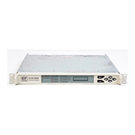
Chapter 1. INTRODUCTION This chapter provides an overview of the SLM-3650 Modem, referred to in this manual as “the modem” (Figure 1-1). Figure 1-1. SLM-3650 Overview The SLM-3650 is a high performance, full-duplex, digital-vector, modulator/demodulator that meets the open network requirements of the INTELSAT Earth Station Standards (IESS) -308, -309, -310, and –315 (Turbo only) emulation specifications for the... -
Page 19: Standard Features
SLM-3650 Satellite Modem Revision 3 Introduction MN/SLM3650.IOM • Satellite Multiservice System (SMS) Additionally, the modem can be used for many closed network satellite communications systems. The modem provides: • High performance with narrow occupied bandwidth • Automatic signal acquisition •... -
Page 20: Modes Of Operation
SLM-3650 Satellite Modem Revision 3 Introduction MN/SLM3650.IOM 1.1.2 Modes of Operation The following main modes of operation are supported: ASYNC Overhead Interface with AUPC SDM-100 Emulation Custom SDM-650 Emulation Drop & Insert (D&I) SDM-6000 Emulation EFD Closed Network SDM-300 Emulation... - Page 21 SLM-3650 Satellite Modem Revision 3 Introduction MN/SLM3650.IOM The modem is used in Single Channel Per Carrier (SCPC) applications with the following specifications: • Modulator type: QPSK, BPSK, 8-PSK, OQPSK, and TPC • Forward Error Correction: 1/2, 21/44, 5/16, 3/4, 7/8, 1/1, or 2/3 •...
-
Page 22: Modem Construction
SLM-3650 Satellite Modem Revision 3 Introduction MN/SLM3650.IOM 1.1.3 Modem Construction The modem contains: Built-in TX and RX frequency synthesizers scramblers/descramblers Differential encoder/decoder Multi-rate FEC convolutional Viterbi and Sequential Decoder The modem is a complete, self-contained unit in standard, one-rack unit (1 RU), 19-inch (48 cm), rack-mountable enclosure weighing approximately 11 lbs (5 kg). -
Page 23: Options
SLM-3650 Satellite Modem Revision 3 Introduction MN/SLM3650.IOM Options Refer to Table 1-1 for options. Table 1-1. Options Option Requirements -20 dB return loss 50 to 180 MHz 50Ω IF Impedance -20 to +5 dBm IF output < 45 dBc at data rates < 64 kbps... -
Page 24: Fast Options
FAST system. For detailed descriptions of the FAST feature and all options, refer to Appendix A. Note: Comtech EF Data has included a DEMO Mode in the Utility Menu. This feature will allow the operator to experience any of the FAST options. This feature has a 60- minute time limit, after which, the unit will return to its previous configuration. -
Page 25: Factory-Installed Options
6. Duplex Reed-Solomon and Turbo can be installed together; however, only one can be used at a time. 1.2.2 Factory-Installed Options Consult a Comtech EF Data Customer Support representative for modem options. The following options are installed at the factory: • Output Impedance: 75Ω (50Ω... -
Page 26: Figure 1-3. Block Diagram
SLM-3650 Satellite Modem Revision 3 Introduction MN/SLM3650.IOM 1.2.4 Breakout Panels The UB-530 universal breakout panel (BOP) is an option for breaking out the V.35, G.703, EIA-232, or EIA-422 signals as well as the overhead ESC and Alarm signals. When the modem is equipped with a 50-pin data I/O connector, the use of the BOP is required to interface with the customer data connector to the modem. -
Page 27: Ub-530 Breakout Panel
Note: The 25-pin connector at J3 on the UB-300 is not an EIA-530 pinout. For more information, refer to the Comtech EF Data UB-300 Universal Breakout Panel Installation and Operation Manual. 1.2.4.2 UB-530 Breakout Panel Alternate part for UB-300. -
Page 28: Modem Assemblies
SLM-3650 Satellite Modem Revision 3 Introduction MN/SLM3650.IOM Modem Assemblies Table 1-3. Comtech EF Data Part Numbers for Various Modules Part Number Nomenclature Comments PL/6096 Top Assy SLM-3650 PL/5303-41 Panel Assy, Front SLM-3650 KT/6095 KT/6596 PL/5305-2 Overhead Interface Assy, PCB Interface Board for G.703, IDR, IBS, AUPC, D&I Without Antenna... -
Page 29: Specifications
Revision 3 Introduction MN/SLM3650.IOM Specifications 1.4.1 Modem Specifications Table 1-4 lists the operating of the modem. Table 1-4. SLM-3650 Satellite Modem Specifications General Specifications Operating Frequency Range 50 to 180 MHz Synthesized in 1 Hz steps Modulation Types 8-PSK QPSK... - Page 30 SLM-3650 Satellite Modem Revision 3 Introduction MN/SLM3650.IOM Table 1-4. SLM-3650 Satellite Modem Specifications (Continued) General Specifications (Continued) Loopback Modes Baseband (near end and far end) Interface (near end and far end) D&I baseband (insert data into drop data out) IF Loopback (near end)
- Page 31 SLM-3650 Satellite Modem Revision 3 Introduction MN/SLM3650.IOM Table 1-4. SLM-3650 Satellite Modem Specifications (Continued) Remote Control Specifications Serial Interface EIA-232 or EIA-485 (2- or 4-wire) Baud Rate 150 to 19200 Mbps Signals Controlled Transmit Frequency Receive Frequency Transmit Power Transmitter On/Off...
-
Page 32: Ber Performance Specifications
SLM-3650 Satellite Modem Revision 3 Introduction MN/SLM3650.IOM BER Performance Specifications Table 1-5 through Table 1-9 lists the Bit Energy-to-Noise Ratio (E ) required to achieve 10 to 10 BER. 1.5.1 Viterbi Decoder BER Table 1-5 lists the Viterbi specifications for the E... -
Page 33: Figure 1-4. Viterbi Ber Performance Curves
SLM-3650 Satellite Modem Revision 3 Introduction MN/SLM3650.IOM 1/2 Rate 3/4 Rate 7/8 Rate SPECIFICATIONS 10.0 11.0 (dB) Figure 1-4. Viterbi BER Performance Curves 1–16 Artisan Technology Group - Quality Instrumentation ... Guaranteed | (888) 88-SOURCE | www.artisantg.com... -
Page 34: Intelsat Viterbi With Reed-Solomon Codec Ber
SLM-3650 Satellite Modem Revision 3 Introduction MN/SLM3650.IOM 1.5.2 INTELSAT Viterbi with Reed-Solomon Codec BER Table 1-6 lists the INTELSAT Viterbi with Reed-Solomon specifications for the E required to achieve 10 to 10 BER for different configurations. Refer to Figure 1-5 for the INTELSAT Viterbi with Reed-Solomon BER curves. -
Page 35: Figure 1-5. Intelsat Viterbi With Reed-Solomon Ber Performance Curves
SLM-3650 Satellite Modem Revision 3 Introduction MN/SLM3650.IOM SPECIFICATIONS 1/2 Rate 3/4 Rate 10.0 11.0 (dB) Figure 1-5. INTELSAT Viterbi with Reed-Solomon BER Performance Curves 1–18 Artisan Technology Group - Quality Instrumentation ... Guaranteed | (888) 88-SOURCE | www.artisantg.com... -
Page 36: Viterbi/Sequential Closed Network Connection Ber (With Reed-Solomon)
SLM-3650 Satellite Modem Revision 3 Introduction MN/SLM3650.IOM 1.5.3 Viterbi/Sequential Closed Network Connection BER (with Reed-Solomon) Table 1-7 lists the Viterbi/Sequential decoder with Reed-Solomon specifications for the required to achieve 10 to 10 BER for different configurations. Refer to Figure 1-6. Viterbi/Sequential Closed Network Connection (with Reed-Solomon) BER Performance Curves. -
Page 37: Figure 1-6. Viterbi/Sequential Closed Network Connection (With Reed-Solomon)
SLM-3650 Satellite Modem Revision 3 Introduction MN/SLM3650.IOM 7/8 RATE 1/2 RATE 3/4 RATE SPECIFICATIONS 10.0 11.0 (dB) Figure 1-6. Viterbi/Sequential Closed Network Connection (with Reed-Solomon) BER Performance Curves 1–20 Artisan Technology Group - Quality Instrumentation ... Guaranteed | (888) 88-SOURCE | www.artisantg.com... -
Page 38: Sequential Decoder Ber (56 Kbps)
SLM-3650 Satellite Modem Revision 3 Introduction MN/SLM3650.IOM 1.5.4 Sequential Decoder BER (56 kbps) Table 1-8 lists the sequential specifications for the E required to achieve 10 to 10 BER at 56 kbps. All values are for operating in BPSK and QPSK modes. Refer to Figure 1-7 for the sequential BER curves. -
Page 39: Figure 1-7. Sequential Ber Specification Curves (56 Kbps)
SLM-3650 Satellite Modem Revision 3 Introduction MN/SLM3650.IOM 1/2 Rate 3/4 Rate 7/8 Rate SPECIFICATIONS 10.0 11.0 (dB) Figure 1-7. Sequential BER Specification Curves (56 kbps) 1–22 Artisan Technology Group - Quality Instrumentation ... Guaranteed | (888) 88-SOURCE | www.artisantg.com... -
Page 40: Sequential Decoder Ber (1544 Kbps)
SLM-3650 Satellite Modem Revision 3 Introduction MN/SLM3650.IOM 1.5.5 Sequential Decoder BER (1544 kbps) Table 1-9 lists the sequential specifications for the E required to achieve 10 to 10 BER at 1544 kbps. All values are for operating in BPSK and QPSK modes. Refer to Figure 1-8 for the Sequential BER curves. -
Page 41: Figure 1-8. Sequential Decoder Ber Specification Curves (1544 Kbps)
SLM-3650 Satellite Modem Revision 3 Introduction MN/SLM3650.IOM 1/2 Rate 3/4 Rate 7/8 Rate SPECIFICATIONS 10.0 11.0 (dB) Figure 1-8. Sequential Decoder BER Specification Curves (1544 kbps) 1–24 Artisan Technology Group - Quality Instrumentation ... Guaranteed | (888) 88-SOURCE | www.artisantg.com... -
Page 42: Trellis 8Psk Ber
SLM-3650 Satellite Modem Revision 3 Introduction MN/SLM3650.IOM 1.5.6 Trellis 8-PSK BER Table 1-10 list the 8-PSK specification for performance with noise and with/without Reed-Solomon. All values are for operating in 8-PSK mode. Refer to Figure 1-9 for the 8-PSK curves. -
Page 43: Figure 1-9. 8-Psk Ber Specification Curves (1544 Kbps)
SLM-3650 Satellite Modem Revision 3 Introduction MN/SLM3650.IOM WITHOUT REED-SOLOMON WITH REED-SOLOMON 10.0 11.0 E /N (db) Figure 1-9. 8-PSK BER Specification Curves 1–26 Artisan Technology Group - Quality Instrumentation ... Guaranteed | (888) 88-SOURCE | www.artisantg.com... -
Page 44: Performance With Noise Turbo Product Codec (Optional)
SLM-3650 Satellite Modem Revision 3 Introduction MN/SLM3650.IOM 1.5.7 Performance with Noise Turbo Product Codec (Optional) Table 1-11 lists the Turbo Codec specification for performance. All values are for operating in 8-PSK mode. Refer to Figure 1-10 for Turbo Product Codec Values. -
Page 45: Figure 1-10. Turbo Product Codec
SLM-3650 Satellite Modem Revision 3 Introduction MN/SLM3650.IOM QPSK/OQPSK 1/2 Rate QPSK/OQPSK 3/4 Rate 8PSK 3/4 Rate BPSK 21/44 Rate (dB) Figure 1-10. Turbo Product Codec 1–28 Artisan Technology Group - Quality Instrumentation ... Guaranteed | (888) 88-SOURCE | www.artisantg.com... -
Page 46: Performance With Uncoded, Bpsk, Qpsk, And Oqpsk
SLM-3650 Satellite Modem Revision 3 Introduction MN/SLM3650.IOM 1.5.8 Performance with Uncoded, BPSK, QPSK, and OQPSK Table 1-12 lists the Turbo Codec specification for performance. All values are for operating in uncoded mode. Refer to Figure 1-11 for uncoded values. Table 1-12. Uncoded Values... -
Page 47: Figure 1-12. Typical Spectral Occupancy
SLM-3650 Satellite Modem Revision 3 Introduction MN/SLM3650.IOM Figure 1-12 shows a typical spectral occupancy curve using the Comtech EF Data filter mask. Figure 1-12. Typical Spectral Occupancy 1–30 Artisan Technology Group - Quality Instrumentation ... Guaranteed | (888) 88-SOURCE | www.artisantg.com... -
Page 48: Dimensional Envelope
Note: Dimensions are listed in inches and centimeters are noted in parentheses. Refer to Figure 1-13. 14.0 1.75 (36) (4.4) 19.0 (4.8) 1.25 (3.2) 3.625 3.625 (9.2) (9.2) Figure 1-13. SLM-3650 Dimensional Drawing 1–31 Artisan Technology Group - Quality Instrumentation ... Guaranteed | (888) 88-SOURCE | www.artisantg.com... -
Page 49: Chapter 2 Installation
Chapter 2. INSTALLATION This chapter provides unpacking and installation instructions, and a description of external connections and backward alarm information. The equipment contains parts and assemblies sensitive to damage by Electrostatic Discharge (ESD). Use ESD precautionary procedures when touching, removing, or inserting PCBs. CAUTION Unpacking The modem and manual are packaged in pre-formed, reusable, cardboard cartons... -
Page 50: Installation
SLM-3650 Satellite Modem Revision 3 Installation MN/SLM3650.IOM Installation The modem arrives fully assembled from the factory. After unpacking the modem, install the modem as follows: 1. If required, install the mounting bracket in equipment rack (Figure 2-1). Install and tighten the bracket bolts. -
Page 51: Figure 2-1. Installation Of The Mounting Bracket
SLM-3650 Satellite Modem Revision 3 Installation MN/SLM3650.IOM Figure 2-1. Installation of the Mounting Bracket Artisan Technology Group - Quality Instrumentation ... Guaranteed | (888) 88-SOURCE | www.artisantg.com... -
Page 52: External Modem Connections
1. Refer to the Comtech EF Data UB-300 Universal Breakout Panel Installation and Operation Manual for connecting the UB-300 breakout panel. 2. Refer to the Comtech EF Data UB-54 Breakout Panel Installation and Operation Manual for connecting the UB-54 breakout panel in a MUX option configuration. -
Page 53: Figure 2-2. Basic Modem, 25-Pin D Connector
SLM-3650 Satellite Modem Revision 3 Installation MN/SLM3650.IOM EX REF RX/IF INPUT TX/IF OUTP UT REMOTE AUX 1 FAULT ALARMS Figure 2-2. Basic Modem, 25-Pin D Connector EX REF RX/IF INPUT TX/IF OUTP UT REMOTE AUX 1 FAULT ALARMS Figure 2-3. Overhead Option, 50-Pin D Connector... -
Page 54: Remote Connector And Pinouts (J6)
SLM-3650 Satellite Modem Revision 3 Installation MN/SLM3650.IOM 2.3.1 Remote Connector and Pinouts (J6) The remote connector is a 9-pin female D connector (J6) located on the rear panel of the modem. Screw locks are provided for mechanical security of the mating connector. -
Page 55: Fault Connector And Pinouts (J7)
SLM-3650 Satellite Modem Revision 3 Installation MN/SLM3650.IOM 2.3.2 Fault Connector and Pinouts (J7) The fault connector provides Form C contact closures for fault reporting. The three Form C summary fault contacts are Modulator, Demodulator, and Common Equipment. The fault interface connection is a 9-pin female D connector (J7) located on the rear panel of the modem. -
Page 56: Data I/O Interface Connector (J8)
SLM-3650 Satellite Modem Revision 3 Installation MN/SLM3650.IOM 2.3.3 Data I/O Interface Connector (J8) The Data I/O interface connector conducts data input and output signals to and from the modem and connects to the customer’s terrestrial equipment, breakout panel, or protection switch. -
Page 57: Table 2-4. 25-Pin D Connector Pinouts
SLM-3650 Satellite Modem Revision 3 Installation MN/SLM3650.IOM Table 2-4. 25-Pin D Connector Pinouts 25-Pin D Connector Pin # EIA-422 EIA-232 V.35 SHLD SHLD SHLD SD-A SD-A RD-A RD-A EIA-A CS-A DM-A SIGGND SIGGND SIGGND RR-A RLSD RT-B SCR-B RR-B TT-B... -
Page 58: Table 2-5. 50-Pin Connector Pinouts
SLM-3650 Satellite Modem Revision 3 Installation MN/SLM3650.IOM Table 2-5. 50-Pin Connector Pinouts 50-Pin D Connector Pin # Async D&I AGC Out AGC Out AGC Out AGC Out EIA-422 TXOctA In ESC TXDB In (485 only) EIA-422 TXOctB In ESC TXDA In (232 only) ESC TXDA In (485 &... - Page 59 SLM-3650 Satellite Modem Revision 3 Installation MN/SLM3650.IOM Notes: 1. IDR configuration connector pinouts: Backward alarm relay contacts are named for normal no fault conditions (BWOx-C connected to BWOx-NC if no fault). Backward alarm inputs should be grounded or pulled logic low to clear the alarm.
-
Page 60: Table 2-6. Optional 37-Pin Connector Pinouts
SLM-3650 Satellite Modem Revision 3 Installation MN/SLM3650.IOM Table 2-6. Optional 37-Pin Connector Pinouts DB37 EIA-422 DB25 V.35/Winchester 1, 19 SIGGND 1, 7 A, B MM (m) SD-A ST-A RD-A RTS-A RT-A CTS-A DM-A RR-A MC-A CC (c) TT-A 20, 37... -
Page 61: Table 2-7. 34-Pin Winchester Connector Pinouts (V.35)
3. Grounding pin CC at the Fireberd interface will change the Fireberd to a DCE device. 4. Comtech EF Data uses the CC and DD for the input master clock (same as the external clock input to the modem). To input an external clock, change the jumper to positions 1 and 2 (the pin closest to the Winchester connector). -
Page 62: Table 2-8. Connector (J8) Matrix
SLM-3650 Satellite Modem Revision 3 Installation MN/SLM3650.IOM 2.3.3.1 Data I/O Interface Connector (J8) Removal/Installation Note: The following procedures outline the removal and installation of the Data I/O connector (J8). These procedures are written with the assumption that the same configured connector will be reinstalled. However, the operator does have an option to install a different configured connector. - Page 63 SLM-3650 Satellite Modem Revision 3 Installation MN/SLM3650.IOM 2.3.3.1.1 Data I/O Connector (J8) Removal 1. (For Ribbon-Configured Connector PL/6031.) Remove Data I/O connector (J8) (Figure 2-7) as follows: a. Remove four screws securing the rear panel to the chassis. b. Pull out rear panel to gain access to disconnect connector (J8).
-
Page 64: Figure 2-7. Data I/O Connector (J8) Removal/Installation
SLM-3650 Satellite Modem Revision 3 Installation MN/SLM3650.IOM For Ribbon-Configured Connector For 50-Pin Connector with Overhead Interface Board Figure 2-7. Data I/O Connector (J8) Removal/Installation 2-16 Artisan Technology Group - Quality Instrumentation ... Guaranteed | (888) 88-SOURCE | www.artisantg.com... -
Page 65: Table 2-9. G.703 T1/E1/Async Interface Adapter
SLM-3650 Satellite Modem Revision 3 Installation MN/SLM3650.IOM 2.3.3.2 G.703 T1 E1/ASYNC Interface Adapter The G.703 T1, E1/ASYNC Interface Adapter has three BNC connectors and a 15-pin sub-miniature D connector. BNC Connectors • BNC connector SD and RD support G.703 unbalanced 75Ω TX and RX data interfaces. -
Page 66: Auxiliary 1 Connector And Pinouts (J9)
SLM-3650 Satellite Modem Revision 3 Installation MN/SLM3650.IOM 2.3.4 Auxiliary 1 Connector and Pinouts (J9) The auxiliary 1 (AUX 1) connector provides: • MOD and DEMOD (TTL) faults • Satellite clock • Satellite I&Q • Automatic Gain Control (AGC) output voltage The faults are open collector levels that indicate a modulator or demodulator failure. -
Page 67: Alarms Connector And Pinouts (J10)
SLM-3650 Satellite Modem Revision 3 Installation MN/SLM3650.IOM 2.3.5 Alarms Connector and Pinouts (J10) The alarms connector provides Form C contact closures for alarm reporting. The two Form C summary fault contacts are Modulator and Demodulator. The alarms connection is a 9-pin female D connector (J10) located on the rear panel of the modem. -
Page 68: Rf Output Connector (Cp1)
SLM-3650 Satellite Modem Revision 3 Installation MN/SLM3650.IOM 2.3.6 RF Output Connector (CP1) Ω Ω CP1 is a TNC connector for the TX-IF signal. The output impedance is 50 optional), and the output power level is -5 to -30 dBm, with +5 to -20 dBm optional. In normal operation, the output will be a modulated result of the Data I/O connector between 50 and 180 MHz, in 1 Hz steps. -
Page 69: Turbo Product Codec Fec
MN/SLM3650.IOM Turbo Product Code FEC The SLM-3650 modem supports the optional Turbo Product Code Forward Error Correction (FEC) feature. A Turbo Product Codec can be installed at the factory or added as a field-installed upgrade to modems currently deployed. Seven new Turbo code rates/modulations are supported: •... -
Page 70: Ber Performance
See Note 10-9 Note: BPSK 5/16 rate Turbo is included for compatibility with other Comtech EF Data equipment. However, implementation limitations prohibit optimum performance at Eb/No values below 4.0 dB. Performance is virtually error free above 4.0 dB Eb/No, and operation below this level is not recommended. -
Page 71: Remote Control & Menu Structure Changes
The units must have a Revision C (or later) main board for the Turbo upgrade. Refer to the following ways to determine the revision status: 1. Provide the SN of the modem to Comtech EF Data for verification of the revision status. -
Page 72: Figure 2-8. Turbo Codec Ber Performance
SLM-3650 Satellite Modem Revision 3 Installation MN/SLM3650.IOM QPSK/OQPSK 1/2 Rate QPSK/OQPSK 3/4 Rate 8PSK 3/4 Rate BPSK 21/44 Rate (dB) Figure 2-8. Turbo Codec BER Performance Observe all normal precautions for handling electrostatic-sensitive devices. CAUTION 2-24 Artisan Technology Group - Quality Instrumentation ... Guaranteed | (888) 88-SOURCE | www.artisantg.com... - Page 73 SLM-3650 Satellite Modem Revision 3 Installation MN/SLM3650.IOM 2.4.4.1 Install Turbo Board and Firmware 1. Disconnect the AC power to the unit. 2. Remove two side screws near front of the modem. Slide top cover back and lift off. 3. Card 1 Removal, refer to unit has top board (Card 1 –...
- Page 74 SLM-3650 Satellite Modem Revision 3 Installation MN/SLM3650.IOM 2.4.4.2 Turbo Set-up: 1. Press the [←] [→] arrow key until the screen reads: “Function Select Utility” then press the Enter key. 2. Press the [→] arrow key until the screen reads: “Utility Modem Type” then press the Enter key.
-
Page 75: Figure 2-9. Card Removal
SLM-3650 Satellite Modem Revision 3 Installation MN/SLM3650.IOM MODULE SIMM SOCKETS CARD 1 OVERHEAD BOARD Figure 2-9. Card Removal 2-27 Artisan Technology Group - Quality Instrumentation ... Guaranteed | (888) 88-SOURCE | www.artisantg.com... -
Page 76: Figure 2-10. Turbo Codec Card Installation
SLM-3650 Satellite Modem Revision 3 Installation MN/SLM3650.IOM TURBO CODEC INSTALLED Figure 2-10. Turbo Codec Card Installation 2-28 Artisan Technology Group - Quality Instrumentation ... Guaranteed | (888) 88-SOURCE | www.artisantg.com... -
Page 77: Duplex Reed-Solomon
There are two ways to determine the revision status: Step Procedure Provide the SN of the modem to Comtech EF Data for verification of the revision status. If the first two digits off the modem SN start with 99, 00 or 01, corresponding to the year of manufacture, then the modem main board is revision C. -
Page 78: Duplex Reed-Solomon Set-Up
SLM-3650 Satellite Modem Revision 3 Installation MN/SLM3650.IOM Disconnect the AC power to the unit. Remove the (2) side screws near the front of the modem. Slide top cover back and lift off. Card 1 Removal, refer to Figure 2. If unit has top board (Card 1 – Overhead board), remove the (4) rear panel screws around the 50-Pin I/O switch module. - Page 79 SLM-3650 Satellite Modem Revision 3 Installation MN/SLM3650.IOM No special setup is required the Reed-Solomon option is avalible as normal under Configuration: Modulator/Demodulator menu. I/O MODULE Card Slot #2 Card Slot #3 SIMM SOCKETS CARD 1 OVERHEAD BOARD Figure 2-11. Duplex Reed-Solomon Setup 2-31 Artisan Technology Group - Quality Instrumentation ...
- Page 80 SLM-3650 Satellite Modem Revision 3 Installation MN/SLM3650.IOM DUPLEX REED-SOLOMON CODEC INSTALLED Figure 2-12. Installation of Duplex Reed-Solomon 2–32 Artisan Technology Group - Quality Instrumentation ... Guaranteed | (888) 88-SOURCE | www.artisantg.com...
-
Page 81: Chapter 3 Operation
For information about remote control operation, refer to Appendix B. Front Panel The modem front panel (Figure 3-1) enables control of modem configuration parameters and displays the modem status. TRANSMIT TRANSMIT POWER ON ENTER SLM-3650 RECEIVE RECEIVE TRANSMITTER ON SATELLITE MODEM COMMON CARRIER DETECT CLEAR... -
Page 82: Table 3-1. Led Indicators
SLM-3650 Satellite Modem Revision 3 Operation MN/SLM3650.IOM All functions are accessible at the front panel by entering one of six pre-defined Function Select categories or levels: • Configuration • Monitor • Faults/Alarms • Stored Faults/Alarms • Remote AUPC (ASYNC mode only) •... -
Page 83: Figure 3-2. Keypad
SLM-3650 Satellite Modem Revision 3 Operation MN/SLM3650.IOM 3.1.2 Front Panel Keypad The front panel keypad permits local operation of the modem. The keypad consists of six keys (Figure 3-2). ENTER CLEAR Figure 3-2. Keypad Each key provides one or more logical functions. These functions are defined in the following table. -
Page 84: Revision Emulation Operation
Revision Emulation Operation To program an emulation mode from Version 1.1.1 through the current version, use the revision emulation feature in the Figure 3-21, Utility Modem Type menu. Refer to Table Table 3-2. SLM-3650 Revision Emulation Software Version Firmware Description of Change 1.1.1... -
Page 85: Menu System
SLM-3650 Satellite Modem Revision 3 Operation MN/SLM3650.IOM Code Rate 3/4 not compatible with a combination of a CSC Closed Modulator Type and Sequential Encoder. Menu System To access and execute all functions, refer to Figure 3-4 through Figure 3-22. Use the Main menu in Figure 3-3 as a quick reference for accessing the modem functions. - Page 86 SLM-3650 Satellite Modem Revision 3 Operation MN/SLM3650.IOM Press [ENTER] to select the desired Configuration menu option. To view the options for the selected configuration parameters, press [ ] or [ ]. To change a configuration ← → parameter, press [ENTER] to begin the change process.
-
Page 87: Figure 3-3. Main Menu
SLM-3650 Satellite Modem Revision 3 Operation MN/SLM3650.IOM SLM3650 "TYPE" VER: 7.1.13 FUNCTION SELECT FUNCTION SELECT FUNCTION SELECT FUNCTION SELECT FUNCTION SELECT FUNCTION SELECT MONITOR FAULTS/ALARMS STORED FLTS/ALMS CONFIGURATION REMOTE AUPC UTILITY (Figure 3-12) (Figure 3-13) (Figure 3-14) REMOTE AUPC CONFIGURATION... -
Page 88: Figure 3-4. Configuration Modulator Menu
SLM-3650 Satellite Modem Revision 3 Operation MN/SLM3650.IOM SLM3650 "TYPE" FUNCTION SELECT CONFIGURATION ASSIGNED FUNCTION SELECT VER: X.X.X CONFIGURATION CONFIGURATION MODULATOR TX FILTER CONFIGURATION MODULATOR TX-X QPSK 1/2 TX-IF FREQUENCY TX-IF OUTPUT 50 to 180 MHz See Description Table. (in 1 Hz steps) -
Page 89: Function Select: Configuration: Modulator
SLM-3650 Satellite Modem Revision 3 Operation MN/SLM3650.IOM 3.4.1 Function Select: Configuration: Modulator Refer to Figure 3-4. TX-X CODE_RATE Upon entry, the current transmitter rate is displayed with the flashing cursor on the first character of the code rate on Line 1. Line 2 displays the data rate. Press [←] or [→] to make the selection. - Page 90 SLM-3650 Satellite Modem Revision 3 Operation MN/SLM3650.IOM SCRAMBLER Programs the scrambler ON or OFF. Upon entry, the current status of the scrambler is displayed. Press [↑] or [↓] to make the selection. Press [ENTER] to execute the change. DIFF. ENCODER Programs the differential encoder ON or OFF.
- Page 91 SLM-3650 Satellite Modem Revision 3 Operation MN/SLM3650.IOM RS ENCODER Conditional: Programming the Reed-Solomon Encoder automatically turns OFF the RF transmitter (because of symbol rate changes). If none of the proper overhead types and data rates apply, the Reed-Solomon Encoder program in the ON state will be rejected (double beep).
-
Page 92: Figure 3-5. Configuration Demodulator Menu
SLM-3650 Satellite Modem Revision 3 Operation MN/SLM3650.IOM SLM3650 "TYPE" FUNCTION SELECT CONFIGURATION VER: X.X.X CONFIGURATION DEMODULATOR DIFFERENTIAL RX-X QPSK 1/2 RX-IF FREQUENCY DESCRAMBLER DECODER 50 TO 180 MHz (in 1 Hz steps) See Description Table. (Always OFF in Turbo mode) -
Page 93: Function Select: Configuration: Demodulator
SLM-3650 Satellite Modem Revision 3 Operation MN/SLM3650.IOM 3.4.2 Function Select: Configuration: Demodulator Refer to Figure 3-5. RX-X CODE_RATE/TYPE Upon entry, the current RX rate is displayed with the flashing cursor on the first character of the code rate on Line 1. Line 2 displays the data rate. Press [←] or [→] to make the selection. - Page 94 SLM-3650 Satellite Modem Revision 3 Operation MN/SLM3650.IOM IF LOOPBACK Programs the modem for IF loopback operation. (Test Mode Configuration) When IF loopback is turned ON, the demodulator input is connected to the modulator output through an internal attenuator. The demodulator is programmed to the same frequency as the modulator.
- Page 95 SLM-3650 Satellite Modem Revision 3 Operation MN/SLM3650.IOM RS DECODER Conditional: If none of the proper overhead types or data rates apply, the Reed-Solomon decoder in the ON state will be rejected (double beep). With the Reed-Solomon decoder turned ON (not OFF or Correction OFF), the corrected BER will be reported from the outer decoder (Reed-Solomon decoder).
-
Page 96: Figure 3-6. Configuration Interface Menu
SLM-3650 Satellite Modem Revision 3 Operation MN/SLM3650.IOM SLM3650 "TYPE" FUNCTION SELECT CONFIGURATION VER: X.X.X CONFIGURATION INTERFACE TX CLOCK SOURCE TX CLOCK PHASE EXT-CLK FREQ BUFFER CLOCK RX (SATELLITE) AUTO TX TERRESTRIAL 8 kHz to 10 MHz NORMAL SCT (INTERNAL) SCT (INTERNAL) EXT. - Page 97 SLM-3650 Satellite Modem Revision 3 Operation MN/SLM3650.IOM CONFIGURATION INTERFACE continued SERVICE DROP CHANNEL DROP FORMAT INSERT FORMAT CHANNEL ADJUST ASSIGNMENTS CHANNEL: TX-1 E1_CCS E1_CCS DROP SAT CHANNEL: TX-2 E1_CAS, E1_IBS E1_CAS, E1_IBS CHANNEL TERR 1 CHANNEL: RX-1 E1_31_TS E1_31_TS (T1, T1_ESF, T1_S, T1_ESF_S...
-
Page 98: Function Select: Configuration: Interface
SLM-3650 Satellite Modem Revision 3 Operation MN/SLM3650.IOM 3.4.3 Function Select: Configuration: Interface Refer to Figure 3-6. TX CLOCK SOURCE Programs the clock source for the modem transmitter clock to the following configurations: TX TERRESTRIAL: Sets the TX clock to recover timing from the incoming clock/data. - Page 99 SLM-3650 Satellite Modem Revision 3 Operation MN/SLM3650.IOM BUFFER CLOCK Programs the interface buffer output clock to one of the following modes: RX (SATELLITE): Sets the output buffer clock to the satellite clock. SCT (INTERNAL): Sets the buffer clock to operate from the modem internal clock. This is also the fallback clock.
- Page 100 SLM-3650 Satellite Modem Revision 3 Operation MN/SLM3650.IOM B-BAND LOOP BACK Programs the modem for baseband loopback operation. (Test Mode Configuration) When baseband loopback is turned ON, the data and timing signals are switched from the demodulator to the modulator on the modem side of the interface. The DTE baseband signals are also looped back from the transmitter data and clock to receiver data and clock on the customer side of the interface.
- Page 101 SLM-3650 Satellite Modem Revision 3 Operation MN/SLM3650.IOM RX DATA FAULT Receive data fault. Selects a receive interface fault monitor of NONE, AIS, or DATA. The data monitored for RX data is coming from the satellite. Refer to TX DATA FAULT for a description of function choices.
- Page 102 SLM-3650 Satellite Modem Revision 3 Operation MN/SLM3650.IOM SERVICE CHANNEL ADJUST This configuration function is used to set service channel audio levels at TX-1, TX-2, RX-1, or RX-2. Upon entry, press [←] or [→] to select the desired service channel. To adjust the service channel level (+10.0 to -20.0 dBm), press [ENTER].
- Page 103 SLM-3650 Satellite Modem Revision 3 Operation MN/SLM3650.IOM DROP CHANNEL Programs the drop channels into the following desired time slot: ASSIGNMENTS • DROP SAT CHANNEL TERR (For T1, T1_ESF, T1_S, T1_ESF_S) • DROP SAT T-SLOT TERR (For all other formats) Upon entry, drop channel 1 and the current time slot are displayed. Press [↑] or [↓] to select the drop channel to be programmed.
- Page 104 SLM-3650 Satellite Modem Revision 3 Operation MN/SLM3650.IOM ASYNC RX BAUD Programs the ASYNC overhead receive baud rate for 110 to 38400 bit/s. Upon entry, the current status of the ASYNC RX baud rate is displayed. Press [↑] or [↓] key to select one baud rate.
- Page 105 SLM-3650 Satellite Modem Revision 3 Operation MN/SLM3650.IOM ASYNC TX PARITY Programs the ASYNC overhead transmit parity for Even, Odd, or None. Upon entry, the current status of the ASYNC TX parity is displayed. Press [↑] or [↓] to make the selection. Press [ENTER] to execute the change.
-
Page 106: Figure 3-7. Configuration Local Aupc Menu
SLM-3650 Satellite Modem Revision 3 Operation MN/SLM3650.IOM CONFIGURATION SLM3650 FUNCTION SELECT LOCAL AUPC VER: X.X.X CONFIGURATION (AUPC option only) AUPC ENABLE NOMINAL POWER MINIMUM POWER MAXIMUM POWER -5.0 to -30.0 dBm -5.0 to -30.0 -5.0 to -30.0 dBm (In 0.5 dBm steps) (In 0.5 dBm steps) -
Page 107: Function Select: Configuration: Local Aupc
SLM-3650 Satellite Modem Revision 3 Operation MN/SLM3650.IOM 3.4.4 Function Select: Configuration: Local AUPC Conditional: This menu is displayed when the Local Modem AUPC = ON located under the Function Select: Utility: Modem Type menu. Refer to Figure 3-7. AUPC ENABLE Programs the AUPC ON or OFF. -
Page 108: Figure 3-8. Configuration Mux
SLM-3650 Satellite Modem Revision 3 Operation MN/SLM3650.IOM SLM3650A "TYPE" FUNCTION SELECT CONFIGURATION MUX VER: X.X.X CONFIGURATION (MUX PCB installed only) TRIBUTARY #n TRIBUTARY #n TRIBUTARY MODE INTERFACE CLOCK/DATA n = 1.8 DISABLED OR SYNC CLK: NRM OR INV 0.6 to 4000 kbit/s... -
Page 109: Function Select: Configuration: Mux
SLM-3650 Satellite Modem Revision 3 Operation MN/SLM3650.IOM 3.4.5 Function Select: Configuration: MUX Optional/ Conditional: The multiplexer (MUX) system provides for 1 to 8 tributary channels to be multiplexed onto a single aggregate carrier. Independent tributary data rates from 600 bps to 4000 kbps in 100 bps increments are supported. This option is used primarily with the SDR-54 receiver. -
Page 110: Figure 3-9. Configuration Flex Mux
SLM-3650 Satellite Modem Revision 3 Operation MN/SLM3650.IOM CONFIGURATION SLM3650 "TYPE" FUNCTION SELECT FLEX MUX VER: X.X.X CONFIGURATION TX CHAN #1 MODE TX CHAN #1 DR TX CHAN #2 MODE TX CHAN #3 MODE D&I ENABLED ASYNC RS-232 1544.0 kbit/s ADPCM ENABLED... - Page 111 SLM-3650 Satellite Modem Revision 3 Operation MN/SLM3650.IOM RX CHAN #1 MODE RX CHAN #1 DR RX CHAN #2 MODE RX CHAN #3 MODE D&I ENABLED ASYNC RS-232 1544.0 kbps ADPCM ENABLED T1/E1 ENABLED SYNC RS-232 2048 kbit/s for BYPASS ADPCM DISABLED...
-
Page 112: Function Select: Configuration: Flex Mux
SLM-3650 Satellite Modem Revision 3 Operation MN/SLM3650.IOM 3.4.6 Function Select: Configuration: Flex Mux Optional/Conditional: This menu is available only if the optional FLEX MUX card is installed, and Modem Type = CUSTOM with Overhead Type = FLEX MUX. Flex Mux is offered as a factory or field installed interface. Simultaneous operation of a main data channel and three overhead channels are supported. - Page 113 SLM-3650 Satellite Modem Revision 3 Operation MN/SLM3650.IOM TX CHAN # 3 MODE Programs the TX Channel # 3 MODE. ASYNC RS232 SYNC RS232 ASYNC RS422 SYNC RS422 AUPC Disabled Press[←] or [→] to move the flashing cursor, and [↑] or [↓] to increment or decrement the selected kbps.
- Page 114 SLM-3650 Satellite Modem Revision 3 Operation MN/SLM3650.IOM TX CHAN # 4 DR Programs the TX Channel # 4 DR. 0.6 to 64 kbps Note: Not displayed if AUPC or Disabled is selected. Press[←] or [→] to move the flashing cursor, and [↑] or [↓] to increment or decrement the selected kbps.
- Page 115 SLM-3650 Satellite Modem Revision 3 Operation MN/SLM3650.IOM RX CHAN # 3 MODE Programs the RX Channel # 3 MODE. ASYNC RS232 SYNC RS232 ASYNC RS422 SYNC RS422 AUPC Disabled Press[←] or [→] to move the flashing cursor, and [↑] or [↓] to increment or decrement the selected kbps.
-
Page 116: Figure 3-10. Configuration Save Menu
SLM-3650 Satellite Modem Revision 3 Operation MN/SLM3650.IOM RX CHAN # 4 PHASE Programs the RX # 4 PHASE. NRM or INV Note: Not displayed if AUPC or Disabled is selected. Press[←] or [→] to move the flashing cursor, and [↑] or [↓] to increment or decrement the selected kbps. -
Page 117: Function Select: Configuration: Save
SLM-3650 Satellite Modem Revision 3 Operation MN/SLM3650.IOM SLM3650 "TYPE" FUNCTION SELECT CONFIGURATION VER: X.X.X CONFIGURATION RECALL CONFIGURATION #x Key: ACCESS TO CONDITIONAL OR Parameter Information SUBMENU OPTION-DEPENDENT x = 1, 2, 3, 4, or 5 Figure 3-11. Configuration Recall Menu 3.4.7... -
Page 118: Figure 3-12. Monitor Menu
SLM-3650 Satellite Modem Revision 3 Operation MN/SLM3650.IOM SLM3650 "TYPE" FUNCTION SELECT VER: X.X.X MONITOR CORRECTED RAW BER Eb/No RECEIVE SIGNAL CURRENT RECEIVE CURRENT RAW BER LEVEL CURRENT CORRECTED BER CURRENT Eb/No or No Data if Carrier is not locked (-10.0 to -60.0 dBm) -
Page 119: Function Select: Monitor
SLM-3650 Satellite Modem Revision 3 Operation MN/SLM3650.IOM 3.4.9 Function Select: Monitor Refer to Figure 3-12. When the Monitor level is entered, press [ ← ] or [ → ] to select the desired monitor function. Each monitor function is displayed in real time as long as it is selected. - Page 120 SLM-3650 Satellite Modem Revision 3 Operation MN/SLM3650.IOM This page is intentionally left blank. 3–40 Artisan Technology Group - Quality Instrumentation ... Guaranteed | (888) 88-SOURCE | www.artisantg.com...
-
Page 121: Function Select: Faults/Alarms
SLM-3650 Satellite Modem Revision 3 Operation MN/SLM3650.IOM 3.4.10 Function Select: Faults/Alarms Refer to Figure 3-13. The Faults/Alarms menu is accessible from the Function Select menu. The Faults/Alarms are similar to monitor functions, as they display the current fault status of the group being displayed. -
Page 122: Figure 3-13. Faults/Alarms Menu
SLM-3650 Satellite Modem Revision 3 Operation MN/SLM3650.IOM SLM3650 "TYPE" FUNCTION SELECT VER: X.X.X FAULTS/ALARMS MODULATOR DEMODULATOR TX INTERFACE RX INTERFACE IF SYNTHESIZER BUFFER UNDERFLOW TX DROP CARRIER DETECT DATA CLOCK SYN BUFFER OVERFLOW TX DATA/AIS IF SYNTHESIZER I CHANNEL RX DATA/AIS... - Page 123 SLM-3650 Satellite Modem Revision 3 Operation MN/SLM3650.IOM 3.4.10.1 Function Select: Modulator: Faults IF SYNTHESIZER Modulator IF synthesizer fault. DATA CLOCK SYN Transmit clock synthesizer fault. Indicates the internal Voltage Controlled Oscillator (VCO) has not locked to the incoming data clock.
- Page 124 SLM-3650 Satellite Modem Revision 3 Operation MN/SLM3650.IOM 3.4.10.3 Function Select: Transmit Interface: Faults TX DROP Drop interface hardware fault. Typically indicates that the drop interface PLL is not locked (D&I only). TX DATA/AIS Data or AIS. When data fault is selected in the Interface Configuration menu, the fault indicates a data stable condition.
- Page 125 SLM-3650 Satellite Modem Revision 3 Operation MN/SLM3650.IOM 3.4.10.4 Function Select: Receive Interface: Faults BUFFER UNDERFLOW Buffer underflow alarm. Indicates that a buffer underflow has occurred. BUFFER OVERFLOW Buffer overflow alarm. Indicates that a buffer overflow has occurred. RX DATA/AIS Data or AIS. When data fault is selected in the Function Select: Configuration Interface menu (Figure 3-6), the fault indicates a data stable condition.
- Page 126 SLM-3650 Satellite Modem Revision 3 Operation MN/SLM3650.IOM 3.4.10.5 Function Select: Common Equipment: Faults BATTERY/CLOCK Battery or clock fault. -12V SUPPLY -12V power supply fault. +12V SUPPLY +12V power supply fault. +5V SUPPLY +5V power supply fault. SELF TEST Built in self test fault.
-
Page 127: Function Select: Stored Faults/Alarms
SLM-3650 Satellite Modem Revision 3 Operation MN/SLM3650.IOM 3.4.11 Function Select: Stored Faults/Alarms Refer to Figure 3-14. The modem stores the first 10 (Flt0 through Flt9) occurrences of fault status changes in each of the following major fault categories: • Modulator •... -
Page 128: Figure 3-14. Stored Faults/Alarms Menu
SLM-3650 Satellite Modem Revision 3 Operation MN/SLM3650.IOM FUNCTION SELECT SLM3650 "TYPE" STORED VER: X.X.X FAULTS/ALARMS MODULATOR x DEMODULATOR x TX INTERFACE x RX INTERFACE x STORED TIME/DATE STORED TIME/DATE STORED TIME/DATE STORED TIME/DATE HH:MM:SS/MM-DD-YY HH:MM:SS/MM-DD-YY HH:MM:SS/MM-DD-YY HH:MM:SS/MM-DD-YY (FAULT LABEL) (FAULT LABEL) -
Page 129: Function Select: Remote Aupc
SLM-3650 Satellite Modem Revision 3 Operation MN/SLM3650.IOM 3.4.12 Function Select: Remote AUPC To view or change the Remote AUPC functions, enter the Remote AUPC menu from the Function Select menu on the front panel. After entering the Remote AUPC menu, press ] or [ ] to select the Configuration or Monitor menu. -
Page 130: Figure 3-15. Remote Aupc Configuration Menu
SLM-3650 Satellite Modem Revision 3 Operation MN/SLM3650.IOM SLM3650 "TYPE" FUNCTION SELECT REMOTE AUPC VER: X.X.X REMOTE AUPC CONFIGURATION AUPC ENABLE B-BAND LOOPBACK TX 2047 PATTERN Control or last known status Control or last known status Control or last known status... -
Page 131: Function Select: Utility
→ sub-menu, and press [ENTER]. Notes: 1. The Function Select: Utility: Factory Setup menu is for Comtech EF Data service personnel only. Entering this menu without authorization may cause the modem to operate incorrectly. 2. Changes in the Function Select: Utility menu may cause changes in other front panel menus. -
Page 132: Figure 3-17. Utility Modulator Menu
SLM-3650 Satellite Modem Revision 3 Operation MN/SLM3650.IOM SLM3650 "TYPE" FUNCTION UTILITY UTILITY VER: X.X.X SELECT UTILITY MODULATOR SINGLE RATE DATA RATE (Modems Only) ASSIGN TX MOD POWER OFFSET MODULATOR TYPE FILTER INTELSAT OPEN -99.9 to +99.9 dB CSC CLOSED See Description Table. - Page 133 SLM-3650 Satellite Modem Revision 3 Operation MN/SLM3650.IOM 3.4.14.1 Function Select: Utility: Modulator Refer to Figure 3-17. UTILITY Displays either Single Code/Data Rate modem only. • If CR/DR is blank, user is permitted to enter CR:__________ code and data rate one time.
- Page 134 SLM-3650 Satellite Modem Revision 3 Operation MN/SLM3650.IOM TX-RS INTERLEAVE Selection of 4, 8, or 16 deep. Upon entry, the current status of the utility menu is displayed. Press [↑] or [↓] to make the selection. Press [ENTER] to execute the change.
-
Page 135: Figure 3-18. Utility Demodulator Menu
SLM-3650 Satellite Modem Revision 3 Operation MN/SLM3650.IOM SLM3650 "TYPE" FUNCTION UTILITY UTILITY VER: X.X.X SELECT UTILITY DEMODULATOR ASSIGN RX DEMODULATOR TYPE DECODER TYPE RX BPSK ORDERING FILTER INTELSAT OPEN CSC CLOSED VITERBI STANDARD See Description Table. FDC CLOSED SEQUENTIAL NON-STANDARD... - Page 136 SLM-3650 Satellite Modem Revision 3 Operation MN/SLM3650.IOM 3.4.14.2 Function Select: Utility: Demodulator Refer to Figure 3-18. ASSIGN RECEIVE FILTERS Upon entry, the current receive rate is displayed with the flashing cursor on the first character of the code rate on Line 1. Line 2 displays the data rate. Press [←] or [→] to make the selection.
- Page 137 SLM-3650 Satellite Modem Revision 3 Operation MN/SLM3650.IOM RX IESS-315 MODE Selection with TURBO. Conditional: Only available when TURBO installed and selected. RX SYMBOL RATE Programmable with 4.800 to 2500 kbps. Status Only. Upon entry, the current status of the utility menu is displayed. Press [↑] or [↓] to make the selection.
-
Page 138: Figure 3-19. Utility Interface Menu
SLM-3650 Satellite Modem Revision 3 Operation MN/SLM3650.IOM SLM3650 "TYPE" FUNCTION SELECT UTILITY VER: X.X.X UTILITY INTERFACE RX TERR TX OVERHEAD TYPE RX OVERHEAD TYPE TX TERR INTERFACE INTERFACE NONE NONE RS-232 RS-232 VSAT IBS VSAT IBS RS-422 RS-422 V.35 V.35 G.703... - Page 139 SLM-3650 Satellite Modem Revision 3 Operation MN/SLM3650.IOM IDR BACKWARD ASYNC TX TYPE ASYNC RX TYPE ALARM CONTROL RS-232 RS-232 BW ALARM RX #4 ON/OFF RS-485 (4-WIRE) RS-485 BW ALARM RX #3 ON/OFF RS-485 (2-WIRE) BW ALARM RX #2 ON/OFF RX ASYNC only...
- Page 140 SLM-3650 Satellite Modem Revision 3 Operation MN/SLM3650.IOM 3.4.14.3 Function Select: Utility: Interface Refer to Figure 3-19. TX OVERHEAD TYPE Select NONE, VSAT-IBS, IDR, IBS, DROP & INSERT, AUPC or ASYNC for TX overhead type. Note: Overhead types are selectable only when Custom is selected for modem type in the Utility: Modem Type menu.
- Page 141 SLM-3650 Satellite Modem Revision 3 Operation MN/SLM3650.IOM E1 INSERT CRC E1 INSERT CRC enable function. Use this option to turn ON or OFF the CRC-4 on the insert side of the E1. The default for this function is ON. If the equipment cannot use the CRC-4 signal, disable the signal by selecting OFF.
-
Page 142: Figure 3-20. Utility System Menu
SLM-3650 Satellite Modem Revision 3 Operation MN/SLM3650.IOM SLM3650 'TYPE' FUNCTION SELECT UTILITY VER: X.X.X UTILITY SYSTEM TIME: HH:MM:SS AM/PM REMOTE BAUD RATE REMOTE ADDRESS REMOTE TYPE DATE: MM/DD/YY PARITY RS-485 (2-WIRE) 1 to 255 Current time and date 2400 RS-485 (4-WIRE) - Page 143 SLM-3650 Satellite Modem Revision 3 Operation MN/SLM3650.IOM EXT AGC: MIN PWR EXT AGC: MAX PWR MASTER RESET 0.0 to 10.0 VOLTS 0.0 to 10.0 VOLTS HARD (in 0.5 v steps) (in 0.5 V steps) SOFT Key: ACCESS TO CONDITIONAL OR...
- Page 144 SLM-3650 Satellite Modem Revision 3 Operation MN/SLM3650.IOM 3.4.14.4 Function Select: Utility: System Refer to Figure 3-20. TIME: HH:MM:SS AM/PM Time of day and date display/set function. DATE: MM/DD/YYYY The current time and date in the modem’s memory are displayed when selected. To change the modem time and/or date, press [ENTER].
- Page 145 SLM-3650 Satellite Modem Revision 3 Operation MN/SLM3650.IOM SELF TEST Select OFF, AUTO, or RUN. After completion of the test, SELF TEST (“PASSED” or “FAILED”) is displayed. OFF bypasses built-in self test. AUTO initiates built-in self test when turning on modem.
- Page 146 SLM-3650 Satellite Modem Revision 3 Operation MN/SLM3650.IOM MASTER RESET Master reset function. CAUTION Initiating a hard reset will reset the modem and place the default configuration settings in ROM. Initiating a soft reset will reset the modem hardware, but saves the current configuration settings.
- Page 147 SLM-3650 Satellite Modem Revision 3 Operation MN/SLM3650.IOM This page is intentionally left blank. 3–67 Artisan Technology Group - Quality Instrumentation ... Guaranteed | (888) 88-SOURCE | www.artisantg.com...
-
Page 148: Figure 3-21. Utility Modem Type Menu
SLM-3650 Satellite Modem Revision 3 Operation MN/SLM3650.IOM SLM3650 "TYPE" FUNCTION SELECT UTILITY VER: X.X.X UTILITY MODEM TYPE CR:_____ MODEM TYPE INTELSAT DATA NRZ DATA I/O DR:_____ Kb 50 PIN 3650-00 One-time displayed menu RS-449 RS-422 3650-02 to allow user to enter... - Page 149 SLM-3650 Satellite Modem Revision 3 Operation MN/SLM3650.IOM CARD #1 OPTIONS CARD #1 TYPE CARD #2 TYPE CARD #3 TYPE ----- OVERHEAD 01 LIST OVERHEAD 01 G.703 MUX 01 REED-SOLOMON 02 REED-SOLOM0N 02 FLEX MUX O1 REED-SOLOMON 03 REED-SOLOMON 03 ASYNC/AUPC...
- Page 150 SLM-3650 Satellite Modem Revision 3 Operation MN/SLM3650.IOM 3.4.14.5 Function Select: Utility: Modem Type Refer to Figure 3-21. UTILITY CR:_________ is a one time displayed menu to permitted the user to enter DR:_________ kb code/data rate for single rate modems. MODEM TYPE...
- Page 151 SLM-3650 Satellite Modem Revision 3 Operation MN/SLM3650.IOM MODEM EMULATION Selects the following types of modem emulation: SDM-100 15.7.1 SDM-300 6.2.2 SDM-308-4 4.03 SDM-308-4 6.05 SDM-308-4 7.03 SDM-308-5 6.08 SDM-309 6.04 SDM-650 4.12A SDM-650 4.16 SDM-6000 5.1.1 REV EMULATION Programs an emulation mode of a previous functional revision. This allows the user to select the CURRENT VERSION or FUNCTIONAL X.
- Page 152 SLM-3650 Satellite Modem Revision 3 Operation MN/SLM3650.IOM MODEM OPTIONS (Status Only.) Displays the installed modem options. Legend High Power (0 or +) 0 = Not Installed, Factory Upgradable High Stability (0 or +) - = Not Installed, FAST Upgradable ASLT...
- Page 153 SLM-3650 Satellite Modem Revision 3 Operation MN/SLM3650.IOM CARD #1 OPTIONS (Status Only.) Overhead 01 List: G.703 (- or +) (- or +) ASYNC/AUPC (- or +) D&I (- or +) (- or +) MUX 01 List: 4 Channel SYNC (- or +)
- Page 154 SLM-3650 Satellite Modem Revision 3 Operation MN/SLM3650.IOM LOCAL MODEM AUPC Configures the modem for the self-monitoring Local Modem AUPC mode and for local TX power control (self-monitoring) due to severe rain fade. Notes: The self-monitoring Local Modem AUPC mode is not used when the ASYNC/AUPC interface option is installed.
-
Page 155: Figure 3-22. Utility Factory Setup Menu
SLM-3650 Satellite Modem Revision 3 Operation MN/SLM3650.IOM SLM3650 "TYPE" FUNCTION SELECT UTILITY VER: X.X.X UTILITY FACTORY SETUP UTILITY FACTORY SETUP Key: ACCESS TO CONDITIONAL OR Parameter Information SUBMENU OPTION-DEPENDENT FACTORY SETTING ONLY Figure 3-22. Utility Factory Setup Menu 3.4.14.6 Function Select: Utility: Factory Setup Refer to Figure 3-22. -
Page 156: Figure 3-23. Rf Loopback
SLM-3650 Satellite Modem Revision 3 Operation MN/SLM3650.IOM DATA IBS or IDR CUSTOMER ENCODER/ TRANSMIT RF TX = 70 MHz INTERFACE MODULATOR DATA EQUIPMENT ANTENNA REMOTE SERIAL MICRO- INTERFACE POWER SUPPLY AC POWER COMPUTER FAULT INDICATORS RX = 73 MHz RECEIVE RF... -
Page 157: Figure 3-25. Baseband Loopback
SLM-3650 Satellite Modem Revision 3 Operation MN/SLM3650.IOM IBS OR IDR ENCODER/ CUSTOMER TRANSMIT RF MODULATOR DATA EQUIPMENT INTERFACE ANTENNA REMOTE SERIAL MICRO- INTERFACE POWER SUPPLY AC POWER COMPUTER FAULT INDICATORS DEMODULATOR/ RECEIVE RF DECODER EQUIPMENT SATELLITE MODEM Figure 3-25. Baseband Loopback Note: When baseband loopback is turned ON, data is looped back on the customer side of the interface. -
Page 158: Software Configuration
IDR (Intermediate Data Rate) IESS-308 IBS (INTELSAT Business Service) IESS-309 D&I (Drop & Insert) IESS-308-5 ASYNC Asynchronous Overhead Comtech EF Data Closed Network CUSTOM Access all modes AUPC Automatic Uplink Power Control VSAT-IBS Intelsat compliant No Overhead 3650-00 No Overhead OM-73... -
Page 159: Table 3-4. Idr Parameter Settings
SLM-3650 Satellite Modem Revision 3 Operation MN/SLM3650.IOM 3.5.1.1 IDR Operation To operate the modem in the IDR configuration, the following cards must be installed in the modem: • Overhead G.703/IDR/IBS/ASYNC/AUPC/D&I card (PL/5305-1) • 50-pin D relay adapter card (PL/5509) The IDR option is a FAST feature that must be enabled using the front panel and the Utility Modem Type menu. -
Page 160: Table 3-5. Ibs Parameter Settings
SLM-3650 Satellite Modem Revision 3 Operation MN/SLM3650.IOM 3.5.1.2 IBS Operation To operate the modem in the IBS configuration, the following cards must be installed in the modem: • Overhead G.703/IDR/IBS/ASYNC/AUPC/D&I card (PL/5305-1) • 50-pin D relay adapter card (PL/5509) The IBS option is a FAST feature that must be enabled using the front panel and the Utility Modem Type menu. -
Page 161: Table 3-6. D&I Parameter Settings
SLM-3650 Satellite Modem Revision 3 Operation MN/SLM3650.IOM 3.5.1.3 D&I Operation To operate the modem in the Drop & Insert configuration, the following cards must be installed in the modem: • Overhead G.703/IDR/IBS/ASYNC/AUPC/D&I card (PL/5305-1) • 50-pin D relay adapter card (PL/5509) The D&I option is a FAST feature that must be enabled using the front panel and the... -
Page 162: Table 3-8. Asynchronous Parameter Settings
SLM-3650 Satellite Modem Revision 3 Operation MN/SLM3650.IOM 3.5.1.4 ASYNC/AUPC Operation To operate in the Asynchronous/AUPC configuration, the following cards must be installed in the modem: • Overhead G.703/IDR/IBS/ASYNC/AUPC/D&I card (PL/5305-1) • 50-pin D relay adapter card (PL/5509) The ASYNC/AUPC option is a FAST feature that must be enabled using the front panel and the Utility Modem Type menu. - Page 163 Network configuration. The basic modem configuration, which includes the 25-pin D Data I/O connector, supports V.35, EIA-422, and EIA-232 data with no overhead. The Comtech EF Data closed network configuration allows the SLM-3650 to be compatible with any Comtech EF Data closed network application.
-
Page 164: Table 3-9. Efd Closed Network Parameter Settings
SLM-3650 Satellite Modem Revision 3 Operation MN/SLM3650.IOM Table 3-9. EFD Closed Network Parameter Settings Parameter Front Panel Setting Reference Menu Modem Type Utility: Modem Type TX Data/Code Rate TX-V, QPSK 1/2 Configuration : Modulator TX IF Output Configuration: Modulator RX Data/Code Rate... -
Page 165: Table 3-10. Sdm-100 Emulation Parameter Settings
• Replace an SDM-100 requiring service with SLM-3650. • Use SLM-3650 as the backup modem for a rack containing a mix of SDM-100 and SLM-3650 modems. SDM-100 Emulation is typically a closed network application, with no added overhead. The modem does not require any additional hardware to operate in SDM-100 Emulation. -
Page 166: Table 3-11. Sdm-6000 Emulation Parameter Settings
• Replace an SDM-6000 requiring service with SLM-3650. • Use SLM-3650 as the backup modem for a rack containing a mix of SLM-3650 and SDM-6000 modems. The SDM-6000 Emulation can be an open or closed network application. If SDM-6000 application requires the use of IDR, IBS, D&I, or ASYNC overhead, then the Overhead PCB must be installed in the SLM-3650, and the applicable FAST option shall be enabled using the front panel. -
Page 167: Clocking Options
SLM-3650 Satellite Modem Revision 3 Operation MN/SLM3650.IOM Clocking Options Clocking of the data from the terrestrial equipment to the satellite (and vice versa) will depend on the application. This section describes the most common options and recommended configurations. 3.6.1 EIA-232, EIA-422, or V.35 Master/Master Refer to Figure 3-27 for: •... -
Page 168: Idr/Ibs G.703 Master/Master
SLM-3650 Satellite Modem Revision 3 Operation MN/SLM3650.IOM 3.6.3 IDR/IBS G.703 Master/Master Use this application when both earth stations have high stability clocks and the received data is to be clocked to the local network. Refer to Figure 3-29 for: •... -
Page 169: Figure 3-27. Eia-422, Eia-232, Or V.35 Master/Master Clocking Diagram
SLM-3650 Satellite Modem Revision 3 Operation MN/SLM3650.IOM TXCLOCK = TX TERRESTRIAL HIGH STABILITY OSCILLATOR INTERNAL OSCILLATOR TRANSMIT RECEIVE EXT REF TERRESTRIAL SATELLITE DATA CLOCK BUFFER RECOVERY CLOCK BUFFER CLOCK = TX TERRESTRIAL MASTER BUFFER CLOCK = TX TERRESTRIAL CLOCK CLOCK... -
Page 170: Figure 3-28. Eia-422, Eia-232, Or V.35 Master/Slave Clocking Diagram
SLM-3650 Satellite Modem Revision 3 Operation MN/SLM3650.IOM TXCLOCK = TX TERRESTRIAL HIGH STABILITY OSCILLATION TERRESTRIAL INTERNAL OSCILLATOR TRANSMIT RECEIVE EXT REF SATELLITE DATA CLOCK BUFFER RECOVERY CLOCK BUFFER CLOCK = TX TERRESTRIAL MASTER BUFFER CLOCK = RX (SATELLITE CLOCK) CLOCK... -
Page 171: Figure 3-29. Idr/Ibs G.703 Master/Master Clocking Diagram
SLM-3650 Satellite Modem Revision 3 Operation MN/SLM3650.IOM TXCLOCK + TX TERRESTRIAL DATA CLOCK RECOVERY CLOCK HIGH STABILITY OSCILLATOR TERRESTRIAL INTERNAL OSCILLATOR TRANSMIT RECEIVE SATELLITE DATA CLOCK DATA BUFFER RECOVERY CLOCK CLOCK BUFFER CLOCK = TX TERRESTRIAL MASTER BUFFER CLOCK = TX TERRESTRIAL... -
Page 172: Figure 3-30. Idr/Ibs G.703 Master/Slave Clocking Diagram
SLM-3650 Satellite Modem Revision 3 Operation MN/SLM3650.IOM TX CLO CK + TX TERRES TRIA L DATA CLO CK RECO V ERY CLOCK HIG H STAB ILITY O SCILLATO R TE RRESTRIAL INTERNAL O SCILLATO R BO P TRA NSM IT... -
Page 173: Figure 3-31. D&I G.703 Master/Master Clocking Diagram
SLM-3650 Satellite Modem Revision 3 Operation MN/SLM3650.IOM TXCLOCK = TX TERRESTRIAL SEND DATA DROP CLOCK CLOCK RECOVERY TERRESTRIAL INTERNAL OSCILLATOR TRANSMIT RECEIVE EXTERNAL REF. INSERT CLOCK RECOVERY SATELLITE CLOCK CLOCK INSERT BUFFER RECOVERY DATA RX CLOCK = INSERT MASTER RX CLOCK = INSERT... -
Page 174: D&I G.703 Master/Master
SLM-3650 Satellite Modem Revision 3 Operation MN/SLM3650.IOM 3.6.5 D&I G.703 Master/Master In the D&I configuration, the most typical clocking option is the master/master application. Refer to Figure 3-31 for: • Clocking block diagram • Transmit clock options • Buffer clock options... -
Page 175: Figure 3-32. Clock Slip
SLM-3650 Satellite Modem Revision 3 Operation MN/SLM3650.IOM PLESIOCHRONOUS OPERATION IS NOT EXACTLY EQUAL TO f 1) INCOMING TRAFFIC TOO FAST 2) INCOMING TRAFFIC TOO SLOW BIT 1 BIT 1 BIT 1 BIT 1 ERROR ERROR BIT 2 BIT 2 BIT 2... -
Page 176: Figure 3-33. Doppler Shift
SLM-3650 Satellite Modem Revision 3 Operation MN/SLM3650.IOM SATELLITE MOTION AND ORBITAL INCLINATION A SATELLITE IS MAINTAINED AT AN ASSIGNED GEOSTATIONARY GEO-SYNCHRONOUS LOCATION THROUGH THE USE OF INCLINED ORBIT GROUND COMMAND ADJUSTMENTS TO ITS N/S AND E/W LOCATION. THIS SATELLITE PROCESS, KNOWN AS SATELLITE... -
Page 177: Buffer Size
SLM-3650 Satellite Modem Revision 3 Operation MN/SLM3650.IOM 3.7.1 Buffer Size The depth of the receive buffer will depend on four parameters: • Doppler shift caused by satellite • Stability of each clock (plesiochronous/Doppler operation) • Frame/Multiframe length of multiplexed data format •... - Page 178 SLM-3650 Satellite Modem Revision 3 Operation MN/SLM3650.IOM 3.7.1.2 Plesiochronous The stability of station reference clocks is normally 1 x 10 (derived from a cesium standard). While the stability is exceptionally high, the two clocks are not in synchronization with each other and will eventually pass by each other.
-
Page 179: Converting Between Bits And Seconds
SLM-3650 Satellite Modem Revision 3 Operation MN/SLM3650.IOM 3.7.1.3 Frame/Multiframe Length The depth of the receive buffer required has been discussed in Section 3.7.1, and is applicable to all unframed data. When the data is framed (such as 2048 kbps G732, or 1544 kbps G733), it is desirable to provide slips in predefined locations. - Page 180 SLM-3650 Satellite Modem Revision 3 Operation MN/SLM3650.IOM This page is intentionally left blank. 3–100 Artisan Technology Group - Quality Instrumentation ... Guaranteed | (888) 88-SOURCE | www.artisantg.com...
-
Page 181: Chapter 4 Theory Of Operation
Chapter 4. THEORY OF OPERATION This chapter contains the theory of operation information for the Monitor and Control (M&C) section, modulator, demodulator, decoder, overhead interface, backward alarm information. Monitor and Control (M&C) The M&C monitors the modem and provides configuration updates to other modems within the modem when necessary. -
Page 182: Theory Of Operation
SLM-3650 Satellite Modem Revision 3 Theory of Operation MN/SLM3650.IOM 4.1.1 Theory of Operation The M&C card is composed of the following subsections: • Microcontroller with Universal Asynchronous Receiver/Transmitter (UART) • Digital-to-Analog Converter (DAC) • Read Only Memory (ROM) • Analog-to-Digital Converter (ADC) •... - Page 183 SLM-3650 Satellite Modem Revision 3 Theory of Operation MN/SLM3650.IOM The heart of the M&C card is the Dallas 80C310 microcontroller operating at 11 MHz. This microcontroller contains 256 kbytes of internal RAM. The ROM at U8 is 29F040 (512 kbytes).
-
Page 184: Remote Baud Rate
SLM-3650 Satellite Modem Revision 3 Theory of Operation MN/SLM3650.IOM 4.1.2 Remote Baud Rate The remote communications baud rate and parity are programmed by the front panel control in the Utility System menu (refer to Chapter 3). The programmed baud rate and parity are maintained indefinitely in RAM on the M&C module. -
Page 185: Slm-3650 Custom Modem Defaults
SLM-3650 Satellite Modem Revision 3 Theory of Operation MN/SLM3650.IOM 4.1.4 SLM-3650 Custom Modem Defaults Refer to Table 4-1 for custom modem defaults. Note: The following parameters do not revert to default settings after a hard reset: • • Address/Parity/Baud Rate EXT AGC Max Power •... - Page 186 SLM-3650 Satellite Modem Revision 3 Theory of Operation MN/SLM3650.IOM Configuration MUX Tributary #N 2048.0 kbps RS422 Aggregate DR 2305.3 kbps CLK:NRM DATA:NRM MD: SYNC AF:7E2 Flex MUX TX Chan #1 Mode D&I Enabled RX Chan #1 Mode D&I Enabled TX Chan #1 DR 64.0 kbps...
- Page 187 SLM-3650 Satellite Modem Revision 3 Theory of Operation MN/SLM3650.IOM Utility:Utility System Time 12:00:00 AM M&C Firmware FW/NNNNNN-DDR Date 7/04/76 MM/DD/YYYY Remote Baud Rate 9600 bps Boot Firmware FW/NNNNNN-DDR MM/DD/YYYY VER: x.x.x Remote Address FPGA Firmware FW/NNNNNN-DDR MM/DD/YYYY Remote Type RS-485 (2-wire)
-
Page 188: Modulator
SLM-3650 Satellite Modem Revision 3 Theory of Operation MN/SLM3650.IOM Modulator The modulator provides PSK modulated carriers within the 50 to 180 MHz range. The types of modulation that encode the transmitted baseband data from the interface PCB are: • BPSK •... -
Page 189: Modulator Specifications
SLM-3650 Satellite Modem Revision 3 Theory of Operation MN/SLM3650.IOM 4.2.1 Modulator Specifications Refer to Table 4-2 for modulator specifications. Table 4-2. Modulator Specifications Parameter Specification Modulation Types BPSK, QPSK, OQPSK, 8-PSK Data Rate Range 2.4 kbps to 1.25 Mbps 1/2 Rate BPSK 4.8 kbps to 2.5 Mbps... - Page 190 SLM-3650 Satellite Modem Revision 3 Theory of Operation MN/SLM3650.IOM Table 4-2. Modulator Specifications (Continued) Parameter Specification Phase Error 2.5° maximum Filtering Type Nyquist, pre-equalized Spectral Occupancy Spectral density is -30 dB at ± 0.75 symbol rate Spurious and Harmonics -55 dBc, 0 to 500 MHz Output Power Level Range -5 to -30 dBm, ±...
-
Page 191: Theory Of Operation
SLM-3650 Satellite Modem Revision 3 Theory of Operation MN/SLM3650.IOM 4.2.2 Theory of Operation The modulator is composed of eight basic subsections. These subsections are divided into the baseband processing section and the RF section of the modulator. The modulator controls all programmable functions on this module. Fault information from the modulator is sent to the M&C. -
Page 192: Theory Of Modulation Types
SLM-3650 Satellite Modem Revision 3 Theory of Operation MN/SLM3650.IOM The two identical digital Nyquist filters are followed by Direct Digital Modulation. Symbol rates up to 2.5 Mbps can be achieved automatically. The modulated carrier is applied to the RF section for conversion to the correct output frequency. - Page 193 SLM-3650 Satellite Modem Revision 3 Theory of Operation MN/SLM3650.IOM 4.2.3.1 BPSK Encoding The modulator converts transmitted baseband data into a modulated BPSK carrier at 2.4 kbps to 1.25 Mbps (1/2 rate). Using vector analysis of the constellation pattern, BPSK represents one symbol with the carrier phase either at 0° or 180°. The 1/2 rate encoding at the convolutional encoder provides two symbols output for every bit input.
-
Page 194: Demodulator
SLM-3650 Satellite Modem Revision 3 Theory of Operation MN/SLM3650.IOM Demodulator A block diagram of the demodulator is shown in Figure 4-3. The demodulator converts PSK modulated carriers within the 50 to 180 MHz range to a demodulated baseband data stream. The converted modulation types are BPSK, QPSK, and 8PSK (refer to Section 4.2.3 for a description of modulation types). -
Page 195: Demodulator Specifications
SLM-3650 Satellite Modem Revision 3 Theory of Operation MN/SLM3650.IOM 4.3.1 Demodulator Specifications Refer to Table 4-3 for demodulator specifications. Table 4-3. Demodulator Specifications Parameter Specification Modulation Types BPSK, QPSK,OQPSK, 8PSK Data Rate Range 2.4 kbps to 1.25 Mbps 1/2 Rate BPSK 4.8 kbps to 2.5 Mbps... -
Page 196: Theory Of Operation
SLM-3650 Satellite Modem Revision 3 Theory of Operation MN/SLM3650.IOM 4.3.2 Theory of Operation The demodulator functions as an advanced, digital, coherent-phase-lock receiver and decoder. Demodulator faults are also reported to the front panel. The demodulator consists of the following basic subsections. - Page 197 SLM-3650 Satellite Modem Revision 3 Theory of Operation MN/SLM3650.IOM implemented digitally. The DDS performs the function of a VCO in an analog implementation. The recovered data and symbol clocks are then used throughout the demodulator. The soft decision mapper converts the digital I and Q data to 3-bit soft decision values.
-
Page 198: Decoder
SLM-3650 Satellite Modem Revision 3 Theory of Operation MN/SLM3650.IOM Decoder The SLM-3650 can be configured in any of the following configurations: • Basic SLM-3650 (Sequential or Viterbi Decoder) • FAST options (Sequential or Viterbi Decoder) • FAST options with Reed-Solomon hardware (Sequential or Viterbi Decoder) •... -
Page 199: Interface
SLM-3650 Satellite Modem Revision 3 Theory of Operation MN/SLM3650.IOM Interface The terrestrial interface functions include: • MUX various types of ESC into the data • Buffering the receive data • DEMUX various types of ESC from the data • Monitoring and displaying the interface status without interruption of service The interface block diagram is shown in Figure 4-4. -
Page 200: Figure 4-4. Interface Block Diagram
SLM-3650 Satellite Modem Revision 3 Theory of Operation MN/SLM3650.IOM INTERFACE LOOPBACK OVERHEAD RECEIVERS OVERHEAD TXSAT ROCESSORS DATA BASEBAND OVERHEAD LOOPBACK LINE TX TERR DATA RECEIVERS CLOCK RS CODEC DROP/INSERT LINE RXTERR PLESIOCHRONOUS RXSAT DRIVERS DATA DATA BUFFER OVERHEAD DEMUX RXCLK... -
Page 201: Interface Specifications
SLM-3650 Satellite Modem Revision 3 Theory of Operation MN/SLM3650.IOM 4.5.1 Interface Specifications Note: Refer to Appendix A for information on the following: • G.703 • • • Drop and Insert (D&I) • Asynchronous 4.5.1.1 Digital Interfaces Refer to Table 4-4 for digital interfaces. -
Page 202: Table 4-5. Eia-422/Eia-449 Specifications
SLM-3650 Satellite Modem Revision 3 Theory of Operation MN/SLM3650.IOM 4.5.1.2 EIA-422/EIA-449 Specifications Refer to Table 4-5 for EIA-422/EIA-449 specifications. Table 4-5. EIA-422/EIA-449 Specifications Parameter Specification Circuit Supported SD, ST, TT, RD, RT, DM, RR, RS, CS, MC Amplitude (RD, RT, ST, DM, RR) ±... -
Page 203: Table 4-7. Eia-232 Specifications
SLM-3650 Satellite Modem Revision 3 Theory of Operation MN/SLM3650.IOM 4.5.1.4 EIA-232 Specifications Refer to Table 4-7 for EIA-232 specifications. Table 4-7. EIA-232 Specifications EIA-232 Specification Circuit Supported TXD, TXC, RXD, RXC, DSR, DCD, CTS, LL, RTS, MC Driver Amplitude (RXD, RXC, True: 10V, ±... -
Page 204: Plesiochronous/Doppler/Buffer
SLM-3650 Satellite Modem Revision 3 Theory of Operation MN/SLM3650.IOM 4.5.2 Plesiochronous/Doppler/Buffer Data from the DEMUX section is fed into a buffer. This buffer size is user-selectable in bit increments that correspond to the length of an IESS-308 satellite superframe. The increments range from 1 to 32 ms. -
Page 205: Closed Network
SLM-3650 Satellite Modem Revision 3 Theory of Operation MN/SLM3650.IOM 4.5.3 Closed Network Typically, the closed network operation does not add overhead to the terrestrial data. The closed network operation is not dictated by a specification. The terrestrial data and clock are passed through the baseband loopback relay and are translated from the selected baseband format to TTL. -
Page 206: Backward Alarm Theory And Connections
SLM-3650 Satellite Modem Revision 3 Theory of Operation MN/SLM3650.IOM Backward Alarm Theory and Connections Four sets of transmit and receive backward alarms are available to implement the structure defined in IESS-308. Backward alarms are sent to the distant side of an IDR link to signal that trouble has occurred at the receive side (which may have resulted from an improper transmission). - Page 207 SLM-3650 Satellite Modem Revision 3 Theory of Operation MN/SLM3650.IOM A backward alarm being received on a particular link is detected by one of the two following methods: • The backward alarm output drives a FORM C relay with all three contacts available on the data connector.
- Page 208 SLM-3650 Satellite Modem Revision 3 Theory of Operation MN/SLM3650.IOM This page is intentionally left blank. 4–28 Artisan Technology Group - Quality Instrumentation ... Guaranteed | (888) 88-SOURCE | www.artisantg.com...
-
Page 209: Chapter 5 Maintenance
Chapter 5. MAINTENANCE This chapter provides the following information: • System checkout • Fault isolation • Module replacement and identification System Checkout This equipment contains parts and assemblies sensitive to damage by ESD. Use ESD precautionary procedures when touching, removing, or inserting PCBs. -
Page 210: Interface Checkout
SLM-3650 Satellite Modem Revision 3 Maintenance MN/SLM3650.IOM 5.1.1 Interface Checkout Use the following procedure and the test setup in Figure 5-1 to inspect the interface. Figure 5-1. Fault Isolation Test Setup 1. Connect a BER test set to the appropriate modem data connector as shown in Figure 5-2. -
Page 211: Modulator Checkout
SLM-3650 Satellite Modem Revision 3 Maintenance MN/SLM3650.IOM 5.1.2 Modulator Checkout Use the following procedure to check out the modulator: 1. Set up the equipment as shown in Figure 5-1. Refer to Chapter 4 for modulator specifications. 2. Set up the modem for operation by using the Configuration Modulator and Demodulator front panel menus. - Page 212 SLM-3650 Satellite Modem Revision 3 Maintenance MN/SLM3650.IOM Table 5-1. Conversion to S/N and E Chart (dB) Code Rate 1/2 Code Rate 3/4 Code Rate 7/8 (S+N)/N E b /N 0 E b /N 0 E b /N 0 -0.6 10.0 10.5...
-
Page 213: Figure 5-2. Typical Output Spectrum (With Noise)
SLM-3650 Satellite Modem Revision 3 Maintenance MN/SLM3650.IOM RL -49.00 dBm ATTEN 10 dB 2.00 dB/DIV RES BANDWIDTH 10.0 kHz Modem Rate = 2144 kbit/s, 3/4 Rate Coding with 7.7 dB Eb/No (S + N)/N = 10 dB CENTER 70.000 MHz SPAN 1.000 MHz... -
Page 214: Demodulator Checkout
SLM-3650 Satellite Modem Revision 3 Maintenance MN/SLM3650.IOM 5.1.3 Demodulator Checkout Use the following procedure to test the demodulator. 1. Set up the equipment as shown in Figure 5-1. Refer to Chapter 4 for the demodulator specifications. 2. Set up the modem with an external IF loop and level. Use a properly operating modulator, and ensure that power levels, data rates, code rates, etc., are... -
Page 215: Figure 5-4. Typical Eye Constellations
SLM-3650 Satellite Modem Revision 3 Maintenance MN/SLM3650.IOM WITH NOISE WITHOUT NOISE Figure 5-4. Typical Eye Constellations 5–7 Artisan Technology Group - Quality Instrumentation ... Guaranteed | (888) 88-SOURCE | www.artisantg.com... -
Page 216: Fault Isolation
If any of the troubleshooting procedures mentioned earlier in this chapter do not isolate the problem, and Comtech EF Data Customer Support assistance is necessary, have the following information available for the representative: •... -
Page 217: Table 5-2. Slm-3650 Fault Tree
SLM-3650 Satellite Modem Revision 3 Maintenance MN/SLM3650.IOM Table 5-2. SLM-3650 Fault Tree & MODULATOR FAULTS IF SYNTHESIZER DATA CLOCK SYN I CHANNEL Q CHANNEL MODEM REF ACT MODEM REF PLL MODULE CONFIGURATION DEMODULATOR FAULTS CARRIER DETECT IF SYNTHESIZER I CHANNEL... - Page 218 SLM-3650 Satellite Modem Revision 3 Maintenance MN/SLM3650.IOM Table 5-2. SLM-3650 Fault Tree (Continued) & TX INTERFACE FAULTS TX DROP TX DATA/AIS TX CLK PLL TX CLK ACTIVITY TX AUDIO 1 CLIP TX AUDIO 2 CLIP CONFIGURATION RX INTERFACE FAULTS BUFFER UNDERFLOW...
- Page 219 SLM-3650 Satellite Modem Revision 3 Maintenance MN/SLM3650.IOM Table 5-2. SLM-3650 Fault Tree (Continued) & COMMON EQUIP FAULTS BATTERY/CLOCK -12V POWER SUPPLY +12V POWER SUPPLY +5V SUPPLY SELF TEST CONTROLLER INTERFACE MODULE BACKWARD ALARMS (IDR OVERHEAD ONLY) BW ALARM RX #4...
-
Page 220: Faults/Alarms Display
SLM-3650 Satellite Modem Revision 3 Maintenance MN/SLM3650.IOM 5.2.2 Faults/Alarms Display General fault, status, and alarm information are indicated by 10 LEDs located on the modem’s front panel. A fault (red LED) indicates a fault that currently exists in the modem. - Page 221 SLM-3650 Satellite Modem Revision 3 Maintenance MN/SLM3650.IOM 5.2.3.1 Modulator Faults Fault/Alarm Possible Problem and Action IF SYNTHESIZER Modulator IF synthesizer fault. This is considered a major alarm, and will turn off the modulator output. Return the modem for repair. DATA CLOCK SYN Transmit data clock synthesizer fault.
- Page 222 IF SYNTHESIZER Demodulator IF synthesizer fault. Indicates the demodulator IF synthesizer is faulted. This fault is a hardware failure. Contact the Comtech EF Data Customer Support Department. I CHANNEL Indicates a loss of activity in the I channel of the quadrature demodulator.
- Page 223 TX CLOCK PLL Transmitter phase-locked loop fault. Indicates the transmitter PLL is not locked to the reference of the interface transmit clock recovery oscillator. Contact the Comtech EF Data Customer Support Department. TX CLOCK ACT Activity detector alarm of the selected interface transmit clock.
- Page 224 SLM-3650 Satellite Modem Revision 3 Maintenance MN/SLM3650.IOM 5.2.3.4 Receive Interface Faults Fault/Alarm Possible Problem and Action BUFFER UNDERFLOW Buffer underflow alarm. Indicates the plesiochronous buffer has underflowed. Buffer underflow is normally a momentary fault (there are clock problems if this alarm is continuously present).
- Page 225 Buffer clock phase-locked loop fault. The buffer synthesizer is the wrong frequency or will not lock. Ensure the selected buffer clock source is at the proper frequency and level. If the fault continues, contact the Comtech EF Data Customer Support Department. BUFFER CLK ACT Activity detector alarm of the selected interface receive clock.
- Page 226 SLM-3650 Satellite Modem Revision 3 Maintenance MN/SLM3650.IOM 5.2.3.5 Common Equipment Faults Fault/Alarm Possible Problem and Action BATTERY/CLOCK M&C battery voltage or clock fault. Indicates a low voltage in the memory battery. Typically, this fault will be active when a modem has been hard reset or the firmware has been changed.
- Page 227 SLM-3650 Satellite Modem Revision 3 Maintenance MN/SLM3650.IOM 5.2.3.6 Backward Alarms Faults Fault/Alarm Possible Problem and Action BW ALARM RX4 Receive backward alarm #4. The distant end of the link is sending backward alarm #4. This indicates trouble at the distant end, which may be a result of improper transmission at the near end of the link.
- Page 228 SLM-3650 Satellite Modem Revision 3 Maintenance MN/SLM3650.IOM This page is intentionally left blank. 5–20 Artisan Technology Group - Quality Instrumentation ... Guaranteed | (888) 88-SOURCE | www.artisantg.com...
- Page 229 Appendix A . OPTIONS This appendix describes the options available for the SLM-3650. Available options are: • Fully Accessible System Topology (FAST) Options • Conventional Options • Software and Hardware Upgrades • 8-Channel Multiplexer Option • Flex Mux • Turbo The following table is provided to assist the operator through Appendix A: A.1 FAST Accessible...
-
Page 230: Table A-1. Fast Options And Required Configurations
MN/SLM3650.IOM FAST Accessible Options Comtech EF Data’s FAST system allows immediate implementation of different options through the user interface keypad. Some FAST options are available through the basic platform unit, while others require that the unit be equipped with optional hardware or that the hardware be installed in the field. - Page 231 The access code can be purchased at any time from Comtech EF Data. Once obtained, the access code is loaded into the unit through the front panel keyboard or the rear remote port.
- Page 232 Record Card #2 serial number, if displayed: Press [CLEAR]. Contact a Comtech EF Data sales representative to order features. Comtech EF Data Customer Support personnel will verify the order and provide an invoice and instructions. A–4 Artisan Technology Group - Quality Instrumentation ... Guaranteed | (888) 88-SOURCE | www.artisantg.com...
- Page 233 Initialization and will reboot to the factory default settings with the new option available. If a wrong or invalid code is entered, the unit will display Wrong Code Entered! and no changes will occur. Retry the code, verify that the code is correct, or request assistance from Comtech EF Data Customer Support.
- Page 234 Use [←] and [→] to scroll through features. Visually check selected features for a “+” sign. If a “+” sign is evident, the upgrade is completed. If upgrade is incorrect, the menu display will exhibit “WRONG CODE ENTERED.” Repeat procedures. Contact Comtech EF Data Customer Support personnel for further instructions, if the error message remains. A.1.2.6 Variable Data Rates The basic platform modem comes with single data rate capabilities.
- Page 235 The satellite overhead includes an ESC. Use of this channel is not specified by IESS and IESS-309. Comtech EF Data uses the ESC to implement a sampled EIA-232 data link, which works at data rates up to 1/2000 of the satellite rate.
-
Page 236: Table A-2. D&I Specification
SLM-3650 Satellite Modem Revision 3 Options MN/SLM3650.IOM A.1.3.1 D&I Specifications Refer to Table A-2 for D&I specifications. Table A-2. D&I Specifications Parameter Specification Primary Data Circuits Supported T1 DSD, DRD, ISD, IRD E1 DSD, DRD, ISD, IRD Primary Data Rates Supported 1544 kbps per G.703... - Page 237 SLM-3650 Satellite Modem Revision 3 Options MN/SLM3650.IOM Table A-2. D&I Specifications (Continued) Parameter Specification Buffer Depth T1, T1_ESF, E1_CCS, 1, 2, 4, 8, 16, or 32 ms E1_IBS, E1_31_TS E1_CAS 7.5, 15, or 30 ms T1_IBS 6, 12, 18, 24, or 30 ms...
-
Page 238: Figure A-1. D&I With Asynchronous Overhead Block Diagram
SLM-3650 Satellite Modem Revision 3 Options MN/SLM3650.IOM TRANSMIT SECTION ALARM BW ALARM MONITORS ALARM MONITOR FRAMING/TIMING SCRAMBLER MODEM LOGIC (MUX) LPBK RS-232/RS-485 ES TO ES ASYNC INTERFACE TX DEJITTER TERDAT DSD-A DROP T1/E1 BASE G.703 INTERFACE BAND DSD-B TERCLK LPBK... -
Page 239: Figure A-2. D&I With Asynchronous Overhead Data Flow
SLM-3650 Satellite Modem Revision 3 Options MN/SLM3650.IOM Figure A-2. D&I with Asynchronous Overhead Data Flow A–11 Artisan Technology Group - Quality Instrumentation ... Guaranteed | (888) 88-SOURCE | www.artisantg.com... - Page 240 SLM-3650 Satellite Modem Revision 3 Options MN/SLM3650.IOM A.1.3.2 Theory of Operation The main features of the D&I option are as follows: • Data interface • Transmit MUX • Receive DEMUX • • Backward alarm A.1.3.2.1 Data Interference Data interface contains transformer balanced data interfaces that support CCITT G.703...
- Page 241 SLM-3650 Satellite Modem Revision 3 Options MN/SLM3650.IOM As a test mode, the transmit data can be replaced with a 2047 pattern. This selection overrides the AIS. Only user data bits are replaced with the pattern, while the Engineering Service Channel (ESC) (including framing and alarms) will operate normally.
- Page 242 SLM-3650 Satellite Modem Revision 3 Options MN/SLM3650.IOM The operator may select from four other clock sources as a backup: • Insert clock (D&I mode only) • RX satellite • Internal clock source • TX terrestrial Problems occurring on any of the selected clocks will cause the modem to substitute the satellite clock and a fault will be signaled.
- Page 243 SLM-3650 Satellite Modem Revision 3 Options MN/SLM3650.IOM A.1.3.3 D&I Framing Formats The D&I framing formats used in the modem can be divided into T1 and E1 categories, as follows: T1_ESF T1 Extended Super Frame T1 D4 Framing T1_ESF_S T1 Extended Super Frame Special...
-
Page 244: Figure A-3. E1 Framing Formats
SLM-3650 Satellite Modem Revision 3 Options MN/SLM3650.IOM Figure A-3. E1 Framing Formats A–16 Artisan Technology Group - Quality Instrumentation ... Guaranteed | (888) 88-SOURCE | www.artisantg.com... -
Page 245: Figure A-4. T1 Framing Formats
SLM-3650 Satellite Modem Revision 3 Options MN/SLM3650.IOM Figure A-4. T1 Framing Formats A–17 Artisan Technology Group - Quality Instrumentation ... Guaranteed | (888) 88-SOURCE | www.artisantg.com... -
Page 246: Table A-3. D&I Modem Faults
SLM-3650 Satellite Modem Revision 3 Options MN/SLM3650.IOM A.1.3.4 D&I Modem Defaults Refer to Table A-3 for D&I Modem Faults. Table A-3. D&I Modem Faults Modulator Demodulator Data Rate Data Rate TX Rate A 64 kbps, QPSK 1/2 RX Rate A... - Page 247 The rate of asynchronous data transfers may be selected by the operator, with the maximum rate available limited to 1.875 of the synchronous data rate. Note: The asynchronous overhead structure is a Comtech EF Data standard, and is not compatible with IBS or IDR overhead formats. A–19...
-
Page 248: Figure A-5. Async/Aupc Block Diagram
SLM-3650 Satellite Modem Revision 3 Options MN/SLM3650.IOM The ASYNC interface PCB also provides its own Doppler buffer, which has a maximum depth of 32 ms at the highest terrestrial data rate. Buffer fill status can be checked in the Monitor menu on the front panel of the modem. Depth selection and centering of the buffer are provided in the Configuration Interface menu. - Page 249 SLM-3650 Satellite Modem Revision 3 Options MN/SLM3650.IOM A.1.4.1 Local AUPC The AUPC function allows each of two modems in a closed link to control the output of the other modem. Both modems must have the AUPC options enabled. These options are: AUPC ENABLE Enables the AUPC to function locally.
- Page 250 2. Set all configuration parameters. Notes: Comtech EF Data does not recommend increasing the power to the satellite without consulting with the satellite controller. 2. Be careful not to set carrier output to the high-side when there is a loss of carrier due to severe weather.
- Page 251 SLM-3650 Satellite Modem Revision 3 Options MN/SLM3650.IOM A.1.4.2 Remote AUPC This feature allows the user to monitor and control a remote modem location using the front panel or serial port of the local modem. The operator can set or reset the following commands: •...
- Page 252 SLM-3650 Satellite Modem Revision 3 Options MN/SLM3650.IOM A.1.4.3.3 MUX Operation The MUX receives terrestrial and ASYNC data from the selected receivers. The terrestrial data flows into a small First In/First Out (FIFO) buffer. The FIFO buffer aids in the rate exchange between the terrestrial data rate and the overhead rate. The data can be clocked into the MUX by the terrestrial clock or an internal clock.
- Page 253 SLM-3650 Satellite Modem Revision 3 Options MN/SLM3650.IOM The Doppler buffer receives data clocked by the overhead clock from the Demod and an enable line from the DEMUX. The data is stored in RAM. Four options are allowed to clock the data out of the buffer: •...
- Page 254 SLM-3650 Satellite Modem Revision 3 Options MN/SLM3650.IOM A.1.4.3.8 Non-ASYNC Operation The ASYNC interface has pass-through capability. If ASYNC is turned off in the Configuration: Interface menu, then a standard G.703, EIA-422, or V.35 interface is selected. The modem will operate as a standard G.703, EIA-422, or V.35 interface with no overhead.
- Page 255 SLM-3650 Satellite Modem Revision 3 Options MN/SLM3650.IOM A.1.4.3.10 Valid ASYNC Baud Rates The ASYNC baud rates are limited by the terrestrial data rates. The following table shows the relationships between data and baud rates. If DR ≤ 15.999K Maximum baud rate is 150 If DR ≤...
-
Page 256: Table A-4. Async Remote Operation
SLM-3650 Satellite Modem Revision 3 Options MN/SLM3650.IOM A.1.4.5 ASYNC Remote Operation Remote modems can be controlled over the ASYNC channel from the local (or “hub”) modem. Refer to Table A-4 for a list of combinations: Table A-4. ASYNC Remote Operation... -
Page 257: Figure A-6. Remote Async Connection Diagram For Y Cable
SLM-3650 Satellite Modem Revision 3 Options MN/SLM3650.IOM Before remote ASYNC communications can be implemented, the following must occur: • At both the local and remote modems, front panel configuration parameters must be set for each type of configuration. • Industry-standard cables must be used at both modems. -
Page 258: Figure A-7. Remote Async Connection Diagram For Breakout Panel
SLM-3650 Satellite Modem Revision 3 Options MN/SLM3650.IOM 25-PIN ASYNC CONNECTOR BREAKOUT PANEL 50-PIN 25-PIN ASYNC CONNECTOR BREAKOUT PANEL WYSE 50-PIN REMOTE TERMINAL (OR EQUIVALENT) EIA-485 25-PIN CONNECTOR 9-PIN CONNECTOR (INDUSTRY STANDARD) TX -30 dBm ASYNC INTERFACE ASYNC INTERFACE TX -30 dBm... -
Page 259: Table A-5. Local Eia-232 To Remote Eia-232
SLM-3650 Satellite Modem Revision 3 Options MN/SLM3650.IOM A.1.4.5.1 Configuration #1 (Local EIA-232 to Remote EIA-232) Table A-5. Local EIA-232 to Remote EIA-232 #1. Local End Modem Settings for EIA-232 Utility: Interface Menu ASYNC TX and RX Type EIA-232 Configuration: Interface Menu... -
Page 260: Table A-6. Local Eia-232 To Remote Eia-485 (4-Wire
SLM-3650 Satellite Modem Revision 3 Options MN/SLM3650.IOM A.1.4.5.2 Configuration #2 (Local EIA-232 to Remote EIA-485 [4-Wire]) Table A-6. Local EIA-232 to Remote EIA-485 (4-Wire) #2. Local End Modem Settings for EIA-232 (4-Wire) Utility: Interface Menu ASYNC TX and RX Type... -
Page 261: Table A-7. Local Eia-232 To Remote Eia-485 (2-Wire
SLM-3650 Satellite Modem Revision 3 Options MN/SLM3650.IOM A.1.4.5.3 Configuration #3 (Local EIA-232 to Remote EIA-485 [2-Wire]) Table A-7. Local EIA-232 to Remote EIA-485 (2-Wire) #3. Local End Modem Settings for EIA-232 Utility: Interface Menu ASYNC TX and RX Type EIA-232... -
Page 262: Table A-8. Local Eia-485 (4-Wire) To Remote Eia-232
SLM-3650 Satellite Modem Revision 3 Options MN/SLM3650.IOM A.1.4.5.4 Configuration #4 (Local EIA-485 [4-Wire] to Remote EIA-232) Table A-8. Local EIA-485 (4-Wire) to Remote EIA-232 #4. Local End Modem Settings for EIA-485 (4-Wire) Utility: Interface Menu ASYNC TX and RX Type... -
Page 263: Table A-9. Local Eia-485 (4-Wire) To Remote Eia-485 (4-Wire
SLM-3650 Satellite Modem Revision 3 Options MN/SLM3650.IOM A.1.4.5.5 Configuration #5 (Local EIA-485 [4-Wire] to Remote EIA-485 [4-Wire]) Table A-9. Local EIA-485 (4-Wire) to Remote EIA-485 (4-Wire) #5. Local End Modem Settings for EIA-485 (4-Wire) Utility: Interface Menu ASYNC TX and RX Type... -
Page 264: Table A-10. Local Eia-485 (4-Wire) To Remote Eia-485 (2-Wire
SLM-3650 Satellite Modem Revision 3 Options MN/SLM3650.IOM A.1.4.5.6 Configuration #6 (Local EIA-485 [4-Wire] to Remote EIA-485 [2-Wire]) Table A-10. Local EIA-485 (4-Wire) to Remote EIA-485 (2-Wire) #6. Local End Modem Settings for EIA-485 (4-Wire) Utility: Interface Menu ASYNC TX and RX Type... -
Page 265: Table A-11. Local Eia-485 (2-Wire) To Remote Eia-232
SLM-3650 Satellite Modem Revision 3 Options MN/SLM3650.IOM A.1.4.5.7 Configuration #7 (Local EIA-485 [2-Wire] to Remote EIA-232) Table A-11. Local EIA-485 (2-Wire) to Remote EIA-232 #7. Local End Modem Settings for EIA-485 (2-Wire) Utility: Interface Menu ASYNC TX and RX Type... - Page 266 SLM-3650 Satellite Modem Revision 3 Options MN/SLM3650.IOM The local end cable connects the 25-pin female ASYNC connector (on either the breakout panel or the Y cable) to the EIA-485 (2-wire) remote terminal (WYSE or laptop computer). The pinout of the local cable is listed in the following table.
-
Page 267: Table A-12. Local Eia-485 (2-Wire) To Remote Eia-485 (4-Wire
SLM-3650 Satellite Modem Revision 3 Options MN/SLM3650.IOM A.1.4.5.8 Configuration #8 (Local EIA-485 [2-Wire] to Remote EIA-485 [4-Wire]) Table A-12. Local EIA-485 (2-Wire) to Remote EIA-485 (4-Wire) #8. Local End Modem Settings for EIA-485 (2-Wire) Utility: Interface MENU ASYNC TX and RX Type... - Page 268 SLM-3650 Satellite Modem Revision 3 Options MN/SLM3650.IOM The local end cable connects the 25-pin female ASYNC connector (on either the breakout panel or the Y cable) to the EIA-485 (2-wire) remote terminal (WYSE or laptop computer). The pinout of the local cable is listed in the following table.
-
Page 269: Table A-13. Async/Aupc Modem Defaults
SLM-3650 Satellite Modem Revision 3 Options MN/SLM3650.IOM A.1.4.6 ASYNC/AUPC Modem Defaults Refer to Table A-13 for ASYNC/AUPC modem defaults. Table A-13. ASYNC/AUPC Modem Defaults Modulator Demodulator Data Rate Data Rate TX Rate A 64 kbps, QPSK 1/2 RX Rate A... -
Page 270: Figure A-8. Sequential Decoder Block Diagram
SLM-3650 Satellite Modem Revision 3 Options MN/SLM3650.IOM A.1.5 Decoder A.1.5.1 Sequential Decoder The sequential decoder is used in closed network applications, typically in Frequency Division Multiple Access (FDMA) satellite communications systems. The sequential decoder is a FAST option. Refer to Figure A-8 for a block diagram of the sequential decoder. - Page 271 SLM-3650 Satellite Modem Revision 3 Options MN/SLM3650.IOM A.1.5.1.1 Theory of Operation The sequential decoder also works in conjunction with the convolutional encoder at the transmitting modem to correct bit errors in the received data stream from the demodulator. The sequential decoder processes 2-bit quantized I&Q channel data symbols from the demodulator.
-
Page 272: Figure A-9. Viterbi Decoder Block Diagram
SLM-3650 Satellite Modem Revision 3 Options MN/SLM3650.IOM The corrected data is buffered through the output RAM and re-timing circuit, which provides a data stream to the differential decoder and descrambler at the constant rate of the data clock. The data and the clock are then output from the card. -
Page 273: Table A-14. Viterbi Specification
SLM-3650 Satellite Modem Revision 3 Options MN/SLM3650.IOM A.1.5.2.1 Specifications Refer to Table A-14 for Viterbi specification. Table A-14. Viterbi Specification Parameter Specification See Chapter 1 Maximum Data Rate 2.048 Mbps (rate 1/2) 2.048 Mbps (rate 3/4) 2.048 Mbps (rate 7/8) - Page 274 SLM-3650 Satellite Modem Revision 3 Options MN/SLM3650.IOM The branch metrics are then processed by the ASC computer. The ASC computer makes decisions about the most probable transmitted symbol stream with the state metrics computed for the previous 64 decoder inputs.
- Page 275 SLM-3650 Satellite Modem Revision 3 Options MN/SLM3650.IOM A.1.6 IDR operation adds 96 kbps overhead to the terrestrial data. The terrestrial data rates supported are: • 1.544 Mbps (T1) + 96k = 1640 Mbps on the data rate menu • 2.048 Mbps (E1) + 96k = 2144 Mbps on the data rate menu The terrestrial data is passed through the baseband loopback relay and is translated from the G.703 format to TTL with a recovered clock.
- Page 276 SLM-3650 Satellite Modem Revision 3 Options MN/SLM3650.IOM The AIS is detected in the receive data and reported to the M&C. The M&C control inserts AIS into the TX data path. The receive data and selected clock are translated to conform to the G.703 interface, and output through the baseband loopback relay.
-
Page 277: Figure A-10. Idr Interface Block Diagram
SLM-3650 Satellite Modem Revision 3 Options MN/SLM3650.IOM Figure A-10. IDR Interface Block Diagram A–49 Artisan Technology Group - Quality Instrumentation ... Guaranteed | (888) 88-SOURCE | www.artisantg.com... -
Page 278: Table A-15. Idr Specification
SLM-3650 Satellite Modem Revision 3 Options MN/SLM3650.IOM A.1.6.1 IDR Specifications Refer to Table A-15 for IDR specification. Table A-15. IDR Specification Primary Data Rates Supported G.703 1544 kbps 2048 kbps Engineering Service Channel ESC Audio 2 channels at 32 kbps duplex ADPCM channel... -
Page 279: Table A-16. Idr Modem Defaults
SLM-3650 Satellite Modem Revision 3 Options MN/SLM3650.IOM A.1.6.2 IDR Modem Defaults Refer to Table A-16 for IDR modem defaults. Table A-16. IDR Modem Defaults Modulator Demodulator Data Rate Data Rate TX Rate A 1640 kbps, QPSK 3/4 RX Rate A... - Page 280 SLM-3650 Satellite Modem Revision 3 Options MN/SLM3650.IOM A.1.7 IBS operation adds a proportional overhead (1/15) to the terrestrial data. The terrestrial data and clock are passed through the baseband loopback relay and are translated from the selected baseband format to Transistor-Transistor Logic (TTL). The data is scrambled synchronously with the multiframe sync in the multiplexer.
-
Page 281: Figure A-11. Ibs Interface Block Diagram
SLM-3650 Satellite Modem Revision 3 Options MN/SLM3650.IOM Figure A-11. IBS Interface Block Diagram A–53 Artisan Technology Group - Quality Instrumentation ... Guaranteed | (888) 88-SOURCE | www.artisantg.com... -
Page 282: Table A-17. Ibs Specification
SLM-3650 Satellite Modem Revision 3 Options MN/SLM3650.IOM A.1.7.1 IBS Specifications Refer to Table A-17 for IBS specification. Table A-17. IBS Specification Parameter Specification Composite Data Rates Supported N x 64 kbps from 64 kbps to 2048 kbps, with 1/15 overhead Primary Data Circuits Supported G.703 1.544 Mbps SD, RD... -
Page 283: Table A-18. Ibs Modem Defaults
SLM-3650 Satellite Modem Revision 3 Options MN/SLM3650.IOM A.1.7.2 IBS Modem Defaults Refer to Table A-18 for IBS modem defaults. Table A-18. IBS Modem Defaults Modulator Demodulator Data Rate Data Rate TX Rate A 64 kbps, QPSK 1/2 RX Rate A... - Page 284 SLM-3650 Satellite Modem Revision 3 Options MN/SLM3650.IOM A.1.8 Asymmetrical Loop Timing Asymmetrical Loop Timing is the same timing method that is designed into the SDM-650B TROJAN interfaces. Refer to Figure A-12 and Figure A-14 for TX and RX Asymmetrical Loop Timing block diagram. There are two advantages for using Asymmetrical Loop Timing: •...
-
Page 285: Figure A-12. Transmit Section Of The Asymmetrical Loop Timing Block Diagram
SLM-3650 Satellite Modem Revision 3 Options MN/SLM3650.IOM OUTPUT Clock Selection S1 set to: S2 set to: S3 set to: S4 set to: TX TERR (TT) INT (SCT) SCT (INT) EXT REF (See Note 2) SCT (LOOP) EXT REF (See Note 2) -
Page 286: Figure A-13. Receive Section Of The Asymmetrical Loop Timing Block Diagram
SLM-3650 Satellite Modem Revision 3 Options MN/SLM3650.IOM TERR Note: PLL will be bypassed when the RX data rate is set to the TX data rate. This will disable the Asymmetrical Mode. Figure A-13. Receive Section of the Asymmetrical Loop Timing Block Diagram... - Page 287 SLM-3650 Satellite Modem Revision 3 Options MN/SLM3650.IOM Master Site Option No. 2: 1. Set Configuration/Modulator/Modem Reference to INTERNAL. 2. Set Configuration/Interface/EXT-CLK Frequency to 10 MHz to INTERNAL. 3. Set Configuration/Interface/TX Clock Source and Buffer Clock to EXT Clock. Note: Input the 10 MHz clock at either the EXC (CP5) clock, unbalanced input of the SMS-7000 data switch module, or balanced pins 7 and 8 of the switch module, V3.
-
Page 288: Table A-19. G.703 Specifications
SLM-3650 Satellite Modem Revision 3 Options MN/SLM3650.IOM A.1.9.1 G.703 Specifications Refer to Table A-19 G.703 specifications. Table A-19. G.703 Specifications Parameter Specification Primary Data Circuits Supported T1 SD, RD E1 SD, RD Interface Type Transformer coupled symmetrical pair Data Rates T1 1544 kbps ±... -
Page 289: Figure A-14. Reed-Solomon Pcb
SLM-3650 Satellite Modem Revision 3 Options MN/SLM3650.IOM Conventional Options A.2.1 Reed-Solomon Codec Note: Pre-Duplex Reed-Solomon. The modem must have the Reed-Solomon PCB installed to access this feature. The Reed-Solomon Codec PCB is a 4.75” x 6.00” (12.07 x 15.24 cm) daughter card that is located on the main PCB (Figure A-14). -
Page 290: Figure A-15. Reed-Solomon Codec Block Diagram
SLM-3650 Satellite Modem Revision 3 Options MN/SLM3650.IOM The Reed-Solomon Codec works in conjunction with the Viterbi decoder and includes additional framing, interleaving, and Codec processing to provide concatenated FEC and convolutional encoding and decoding. Refer to Figure A-15 for a block diagram of the Reed-Solomon Codec. -
Page 291: Figure A-16. Reed-Solomon Encoder Section Block Diagram
SLM-3650 Satellite Modem Revision 3 Options MN/SLM3650.IOM A.2.1.2 Theory of Operation The Reed-Solomon Codec works in conjunction with the interface card to provide concatenated convolutional encoding and decoding. The two main sections of the Codec are: • Reed-Solomon encoder (Section A.2.1.3) •... - Page 292 SLM-3650 Satellite Modem Revision 3 Options MN/SLM3650.IOM The data and clock signals (MUXDATA and MUXCLK) come from the multiplexer on the main PCB, and are sent to the Reed-Solomon encoder section. Since the data input to the Reed-Solomon encoder is serial, the data passes through a self-synchronizing serial scrambler, in accordance with INTELSAT-308 Rev.
-
Page 293: Figure A-17. Reed-Solomon Code Page Format
SLM-3650 Satellite Modem Revision 3 Options MN/SLM3650.IOM TERRESTRIAL RS CODE DATA RATE (n,k,t) 'RSWORD' 1544 (1640) 225, 205, 10 n BYTES 2048 (2144) 219, 201, 9 k BYTES OF DATA CHECK BYTES 1 RSWORD 1 RS PAGE RS SYNCH PERIOD... -
Page 294: Figure A-18. Reed-Solomon Decoder Section Block Diagram
SLM-3650 Satellite Modem Revision 3 Options MN/SLM3650.IOM A.2.3 Reed-Solomon Decoder Refer to Figure A-18 for a block diagram of the Reed-Solomon decoder section. The Reed-Solomon decoder section includes the following circuits: • Serial/Parallel Converter • RAM Deinterleaver • Parallel/Serial Converter •... -
Page 295: Table A-21. Reed-Solomon Specifications Optional
SLM-3650 Satellite Modem Revision 3 Options MN/SLM3650.IOM Refer to Figure A-17 for the Reed-Solomon code page format. The outer Codec reads the data in blocks of n bytes and recalculates the check bytes that were appended by the encoder. If the recalculated data bytes do not match the check bytes received, the Codec makes the necessary corrections to the data within the data block. - Page 296 SLM-3650 Satellite Modem Revision 3 Options MN/SLM3650.IOM A.2.4 Unpacking This equipment contains parts and assemblies sensitive to damage by ESD. Use ESD precautionary procedures when touching, removing, or inserting PCBs. CAUTION 1. Remove the Reed-Solomon PCB and mounting hardware from the cardboard caddypack and anti-static material.
-
Page 297: Figure A-19. Reed-Solomon Codec Installation
SLM-3650 Satellite Modem Revision 3 Options MN/SLM3650.IOM Reed-Solomon Cards (TX or RX or Duplex in either slot) Figure A-19. Reed-Solomon Codec Installation A–69 Artisan Technology Group - Quality Instrumentation ... Guaranteed | (888) 88-SOURCE | www.artisantg.com... - Page 298 SLM-3650 Satellite Modem Revision 3 Options MN/SLM3650.IOM Full Duplex Reed-Solomon Card The Reed-Solomon Duplex board is a 1.2"x 4.2" daughter card for 300 series modems that can do either Reed-Solomon Encoding or Reed-Solomon Decoding by means of the Reed-Solomon Interface on the Spartan 2 FPGA. See below for a block diagram of the Reed-Solomon Duplex card.
- Page 299 SLM-3650 Satellite Modem Revision 3 Options MN/SLM3650.IOM Design guidelines are per IESS-308/309/310. The Duplex Reed-Solomon Card assembly contains the following IC's: • 1- Spartan 2 FPGA • 1- AHA 4011 encoder • 1- AHA 4011 decoder • 2- 71256 RAM's •...
-
Page 300: Table A-22. R-S Codes
SLM-3650 Satellite Modem Revision 3 Options MN/SLM3650.IOM A.3.1 Reed-Solomon Features The design implements RS encoding and decoding by utilizing the Advanced Hardware AHA4011B chip set. See Table A-22 for R-S codes. Table A-22. R-S Codes Service Data Rate kbps RS Code (n, k, t) - Page 301 SLM-3650 Satellite Modem Revision 3 Options MN/SLM3650.IOM A.3.2 Encoder The encoder inserts the unique word into the data stream for synchronization of the descrambler and the deinterleaver on the decode side. The unique word consists of four hex bytes Ox5AOFBE66, Ox5A being the first bit in time. The unique word is inserted into the last two bytes of the last two blocks of the last page of the interleave frame.
- Page 302 SLM-3650 Satellite Modem Revision 3 Options MN/SLM3650.IOM Figure A-21. Reed-Solomon Encoder Section Block Diagram A.3.3 Interleaver The interleaver is implemented by writing scrambled and RS encoded data (with check bytes) into a static ram in a row format, and reading data out in a column format.
- Page 303 SLM-3650 Satellite Modem Revision 3 Options MN/SLM3650.IOM Figure A-22. RS Codeword Format A.3.4 Decoder A.3.4.1 Correlator On the receive side (decoder), the correlator searches for the unique words of the RS frame. The correlator starts in hunt mode searching for the first two bytes of the unique word.
- Page 304 SLM-3650 Satellite Modem Revision 3 Options MN/SLM3650.IOM A.3.4.2 Error Detection The decoder provides a means to check for uncorrectable RS blocks. The decode Xilinx monitors the CRTN line out of the RS decoder. CRTN is valid during the first byte of each RS block.
- Page 305 SLM-3650 Satellite Modem Revision 3 Options MN/SLM3650.IOM A.3.4.3 Deinterleaver The unique words inserted by the encoder are used by the decoder to detect the frame boundary for synchronization of the descrambler and the de-interleaver. The de- interleaver operates in much the same manner as the interleaver, except it writes scrambled and RS encoded data (with check-bytes) into a static ram in column format and reads in row format.
-
Page 306: Figure A-25. Performance With Noise, Viterbi Decoder And Reed-Solomon (Optional
SLM-3650 Satellite Modem Revision 3 Options MN/SLM3650.IOM A.3.4.4 Performance See Figure A-25 and Table A-23 for operational performance. REED-SOLOMON 1/2 RATE 3/4 RATE 7/8 RATE 10.0 11.0 (dB) Figure A-25. Performance with Noise, Viterbi Decoder and Reed-Solomon (Optional) A–78 Artisan Technology Group - Quality Instrumentation ... Guaranteed | (888) 88-SOURCE | www.artisantg.com... -
Page 307: Table A-23. Performance With Noise, Viterbi Decoder And Reed-Solomon (Optional
SLM-3650 Satellite Modem Revision 3 Options MN/SLM3650.IOM Table A-23. Performance with Noise, Viterbi Decoder and Reed-Solomon (Optional) E b /N 0 (dB) Specification 1/2 Rate 3/4 Rate 7/8 Rate A.3.4.5 Digital Data Rates The digital data rate is selectable in 1 Hz steps. The modem automatically calculates and sets the symbol rate. - Page 308 SLM-3650 Satellite Modem Revision 3 Options MN/SLM3650.IOM Software and Hardware Installation/Upgrades A.4.1 Overhead Interface PCB Installation The overhead interface PCB may be installed at the factory or in the field. The overhead interface PCB is required to access certain options and functionality of the modem.
- Page 309 SLM-3650 Satellite Modem Revision 3 Options MN/SLM3650.IOM A.4.2 Installation This equipment contains parts and assemblies sensitive to damage by ESD. Use ESD precautionary procedures when touching, removing, or inserting PCBs. CAUTION The following tool is required to install the overhead interface PCB:...
- Page 310 SLM-3650 Satellite Modem Revision 3 Options MN/SLM3650.IOM Figure A-26. Overhead Interface PCB Installtion A.4.3 Hardware Upgrades A.4.3.1 Main PCB The main PCB has two field-changeable firmware chips. If necessary, these chips can be removed and new chips added to allow for additional options, enhancements, or repairs.
-
Page 311: Figure A-27. Main Board Field-Changeable Chips
SLM-3650 Satellite Modem Revision 3 Options MN/SLM3650.IOM FIELD-CHANGEABLE CHIPS Figure A-27. Main Board Field-Changeable Chips A–83 Artisan Technology Group - Quality Instrumentation ... Guaranteed | (888) 88-SOURCE | www.artisantg.com... -
Page 312: Figure A-28. Overhead Board Field-Changeable Chips
SLM-3650 Satellite Modem Revision 3 Options MN/SLM3650.IOM A.4.3.2 Overhead Interface PCB The overhead interface PCB has four field-changeable firmware chips. If necessary, these chips can be removed and new chips added to allow for additional options, enhancements, or repairs. Currently, there are no foreseeable requirements for this task. -
Page 313: Figure A-29. 8-Channel Multiplexer Pcb
SLM-3650 Satellite Modem Revision 3 Options MN/SLM3650.IOM A.4.4 8-Channel Multiplexer Option The multiplexer (MUX) system (Figure A-29) provides for 1 to 8 tributary channels to be multiplexed onto a single aggregate carrier. Independent tributary data rates from 600 bit/s to 4000 kbps in 100 bit/s increments are supported. This option is used primarily with the SDR-54 receiver. - Page 314 SLM-3650 Satellite Modem Revision 3 Options MN/SLM3650.IOM A.4.4.1 Installation The following tool is required to install the 8-Channel Mux PCB: Description Application Phillips Screwdriver To remove and replace cross-point screws. Install the 8-Channel Mux PCB as a daughter card on the main PCB as follows: The equipment contains parts and assemblies sensitive to damage by Electrostatic Discharge (ESD).
-
Page 315: Table A-24. Specification Summary
SLM-3650 Satellite Modem Revision 3 Options MN/SLM3650.IOM A.4.4.2 Specifications Summary Refer to Table A-24 and Table A-25 for specification summary and MUX data for connector (J10). Table A-24. Specification Summary System Specification Number of Channels 1 to 8, the data rate for each channel is independently configurable. -
Page 316: Table A-25. Mux Data 100-Pin Connector (J10
SLM-3650 Satellite Modem Revision 3 Options MN/SLM3650.IOM Table A-25. MUX Data 100-Pin Connector (J10) MUX Data 100 Pin Rear Panel Connector (J10) Pin # Circuit Description Pin # Circuit Description GROUND TC232_5 EIA-232, TX CLK, TRIB5 TD232_5 EIA-232, TX DAT, TRIB5... -
Page 317: Table A-27. Multiplexer Specification
SLM-3650 Satellite Modem Revision 3 Options MN/SLM3650.IOM A.4.5 Flex Mux Flex Mux (Figure A-30) PCB is offered as a factory or field installable interface. Simultaneous operation of a main data channel and three overhead channels are supported. The main data channel is a G.703 type electrical interface at E1 (2048 kbps) or T1 (1544 kbps) terrestrial data rate and supports both pass through and D&I modes of... -
Page 318: Figure A-30. Flex Mux
SLM-3650 Satellite Modem Revision 3 Options MN/SLM3650.IOM Figure A-30. Flex Mux Table A-26. System Specifications System Specifications Number of Channels 1 to 4, Each Channel is independently configurable. User Channel #1 G.703 E1 with Nx64 kbps channels. Drop and Insert G.703T1 with Nx64 kbps channels. -
Page 319: Table A-28. Demultiplexer Specific Specifications
SLM-3650 Satellite Modem Revision 3 Options MN/SLM3650.IOM Table A-27. Multiplexer Specifications Multiplexer Specific Specifications Tributary Data Interface (Synchronous Mode) The multiplexer supports data from each tributary. The tributary interfaces use DCE conventions with data (send data) sourced by external equipment and clock (send timing) sourced by the multiplexer. - Page 320 SLM-3650 Satellite Modem Revision 3 Options MN/SLM3650.IOM A.4.5.1 Installation The following tool is required to install the Flex Mux PCB: Description Application Phillips Screwdriver To remove and replace cross-point screws. Install the Flex Mux PCB as a daughter card on the main PCB as follows: The equipment contains parts and assemblies sensitive to damage by Electrostatic Discharge (ESD).
-
Page 321: Table A-29. 50-Pin Connector Pin Assignments
SLM-3650 Satellite Modem Revision 3 Options MN/SLM3650.IOM A.4.5.2 Pin Assignment Refer to Table A-29 for 50-pin connector pin assignments. Table A-29. 50-Pin Connector Pin Assignments Pin # Signal Name Description Pin # Signal Name Description 1, 2 RT2-A Receive Timing -... - Page 322 Typically, in QPSK, 8PSK mode the Demod and decoder can remain synchronized 2 – 3 dB below the Viterbi/Reed-Solomon or TCM cases. With this revision of the SLM-3650, Comtech EF Data now provides the best Forward Error Correction technology currently available, offering a very broad range of TPC code rates, combined with the entire range of modulation types.
- Page 323 SLM-3650 Satellite Modem Revision 3 Options MN/SLM3650.IOM Table A-30.Turbo Product Coding Processing Delay Comparison FEC Mode (64 kbps data rate) End-to-end delay, ms Viterbi, Rate 1/2 Sequential, Rate 1/2 Viterbi Rate 1/2 + Reed-Solomon Sequential Rate 1/2 + Reed-Solomon Turbo Product Coding, Rate 3/4, {O}QPSK...
- Page 324 1. The occupied bandwidth is defined at the width of the transmitted spectrum taken at the –10 dB points on the plot of power spectral density. This equates to 1.19 x symbol rate for the SLM-3650 TX filtering. 2. Included for comparison purposes.
- Page 325 There are occasions where a user may desire to operate a satellite link with No FEC of any kind. For this reason, the SLM-3650 offers this uncoded mode for three modulation types - BPSK, QPSK and OQPSK. However, the user should be aware of some of the implications of using this approach.
- Page 326 The problem becomes progressively better with increasing symbol rate. Comtech EF Data is not responsible for incorrect operation if the user does not adhere to these guidelines when using uncoded operation.
- Page 327 SLM-3650 Satellite Modem Revision 3 Options MN/SLM3650.IOM Eb/No in dB 1E-1 Uncoded BPSK/QPSK Viterbi Decoding 1E-2 Typical Performance 1E-3 1E-4 1E-5 1E-6 Specification limit, Rate 7/8 1E-7 Coding 1E-8 Specification Specification limit, Rate 3/4 limit Rate 1/2 Coding Coding 1E-9 Figure A-31.
-
Page 328: Figure A-32. Sequential Decoding 64 Kbps
SLM-3650 Satellite Modem Revision 3 Options MN/SLM3650.IOM Eb/No in 1E-1 Sequential Uncoded Decoding 64 kbps 1E-2 Typical 1E-3 Performance 1E-4 1E-5 1E-6 Specificatio 1E-7 limit, Rate 7/8 Coding 1E-8 Specificatio Specificatio limit, Rate 1/2 limit, Rate 3/4 Coding Coding 1E-9 Figure A-32. - Page 329 SLM-3650 Satellite Modem Revision 3 Options MN/SLM3650.IOM Eb/No in dB 1E-1 Sequential Uncoded BPSK/QPSK Decoding 1024 kbps 1E-2 1E-3 Typical Performance 1E-4 1E-5 1E-6 Specification 1E-7 limit, Rate 7/8 Coding 1E-8 Specification limit Rate 1/2 Specification Coding limit, Rate 3/4...
- Page 330 SLM-3650 Satellite Modem Revision 3 Options MN/SLM3650.IOM Eb/No in dB 1E-1 Sequential Uncoded BPSK/QPSK Decoding 2048 kbps 1E-2 1E-3 1E-4 1E-5 1E-6 Typical performance, Rate 7/8 Coding 1E-7 1E-8 Typical Typical performance, performance, Rate 3/4 Rate 1/2 Coding Coding 1E-9 Figure A-34.
- Page 331 SLM-3650 Satellite Modem Revision 3 Options MN/SLM3650.IOM Eb/No in dB 1E-1 Viterbi with Uncoded BPSK/QPSK concatenated RS 220,200 1E-2 Outer Code Sync threshold, Rate 3/4 1E-3 Sync threshold, Rate 7/8 1E-4 Combined sync 1E-5 threshold, demod and Viterbi Decoder, Rate 1/2...
- Page 332 SLM-3650 Satellite Modem Revision 3 Options MN/SLM3650.IOM Eb/No in dB 1E-1 Sequential Uncoded BPSK/QPSK with concatenated 1E-2 RS 220,200 Outer Code 512 kbps 1E-3 1E-4 Combined sync threshold, demod and Sequential 1E-5 Decoder, Rate 1/2 Sync threshold, Rate 3/4 Specification...
- Page 333 SLM-3650 Satellite Modem Revision 3 Options MN/SLM3650.IOM Eb/No in dB 1E-1 8-PSK/TCM Rate 2/3 Uncoded BPSK/QPSK Decoding, with and without RS Outer 1E-2 Code 1E-3 1E-4 Typical Performance 1E-5 1E-6 1E-7 1E-8 Specification limit Specification Rate 2/3 Coding and limit, Rate 2/3...
-
Page 334: Figure A-38. Comtech Ef Data Turbo Product Codec Rate 3/4 Qpsk/Oqpsk, And 8Psk
QPSK/OQPSK Rate 3/4 1E-3 8-PSK 1E-4 1E-5 1E-6 1E-7 1E-8 Typical performance 1E-9 Figure A-38. Comtech EF Data Turbo Product Codec Rate 3/4 QPSK/OQPSK, and 8PSK A–106 Artisan Technology Group - Quality Instrumentation ... Guaranteed | (888) 88-SOURCE | www.artisantg.com... - Page 335 Glossary The following is a list of acronyms and abbreviations that may be found in this manual. Acronym Definition Ω Ohms 8-PSK 8-Phase Shift Keying Ampere Alternating Current Adjust Automatic Gain Control Alarm Indication Signal Amplitude Modulation ASCII American Standard Code for Information Interchange ASYNC Asynchronous AUPC...
- Page 336 SLM-3650 Satellite Modem Revision 3 Glossary MN/SLM3650.IOM Electronic Industries Association Electro-Magnetic Compatibility Engineering Service Circuit or Engineering Service Channel Electrostatic Discharge EXT REF CLK External Reference Clock FAST Fully Accessible System Topology FIFO First in/First Out Firmware Ground Hertz (cycle per second)
- Page 337 SLM-3650 Satellite Modem Revision 3 Glossary MN/SLM3650.IOM SYNC Synchronize Terminal Timing Transistor-Transistor Logic Transmit (Transmitter) TXCLK Transmit Clock Transmit Data Universal Brreakout box United States Volts Volts, Alternating Current Voltage-Controlled Oscillator Volts, Direct Current Viterbi Watt Artisan Technology Group - Quality Instrumentation ... Guaranteed | (888) 88-SOURCE | www.artisantg.com...
- Page 338 SLM-3650 Satellite Modem Revision 3 Glossary MN/SLM3650.IOM This page is intentionally left blank. Artisan Technology Group - Quality Instrumentation ... Guaranteed | (888) 88-SOURCE | www.artisantg.com...
- Page 339 Index 25-Pin D Connector Pinouts, 2-9 34-Pin Winchester Connector Pinouts (V.35), 2-13 37-Pin Connector Pinouts, 2-12 50-Pin Connector Pinouts, 2-10, A-93 8-Channel Multiplexer Option, A-85 D&I G.703 Master/Master, 3-96 AC Power Connector, 2-20 D&I Modem Fault, A-18 Alarms Connector and Pinouts (J10), 2-19 D&I Operations, 3-82 ASYNC/AUPC Modem Defualts, A-41 D&I Specification, A-8...
- Page 340 SLM-3650 Satellite Modem Revision 3 Index MN/SLM3650.IOM Local EIA-485 (2W) to Remote EIA-485 (4W), A-39 Local EIA-485 (4W) to Remote EIA-232, A-34 Local EIA-485 (4W) to Remote EIA-485 (2W), A-36 Factory-Installed Options, 1-8 Local EIA-485 (4W) to Remote EIA-485 (4W), A-35...
- Page 341 Upgrading to Duplex Reed-Solomon, 2-29 Sequential Decoder BER (56 kbps), 1-22 Upgrading to Turbo, 2-23 Sequential Decoder BER (1544 kbps), 1-24 Unpacking, 2-1 SLM-3650 Customer Modem Defaults, 4-5 SLM-3650 Fault Tree, 5-9 SLM-3650 Revision Emulation, 3-84 Software Configuration, 3-78 Specifications, 1-12, A-62 V.35 Specification, 4-22...
- Page 342 SLM-3650 Satellite Modem Revision 3 Index MN/SLM3650.IOM This page is intentionally left blank. i–4 Artisan Technology Group - Quality Instrumentation ... Guaranteed | (888) 88-SOURCE | www.artisantg.com...
- Page 343 METRIC CONVERSIONS Units of Length Unit Centimeter Inch Foot Yard Mile Meter Kilometer Millimeter 1 centimeter — 0.3937 0.03281 0.01094 6.214 x 10 0.01 — — 1 inch 2.540 — 0.08333 0.2778 1.578 x 10 0.254 — 25.4 1 foot 30.480 12.0 —...
- Page 344 2114 85281 WEST TH STREET TEMPE ARIZONA 480 • 333 • 2200 PHONE 480 • 333 • 2161 Artisan Technology Group - Quality Instrumentation ... Guaranteed | (888) 88-SOURCE | www.artisantg.com...
- Page 345 Artisan Technology Group is your source for quality new and certified-used/pre-owned equipment SERVICE CENTER REPAIRS WE BUY USED EQUIPMENT • FAST SHIPPING AND DELIVERY Experienced engineers and technicians on staff Sell your excess, underutilized, and idle used equipment at our full-service, in-house repair center We also offer credit for buy-backs and trade-ins •...