Agilent Technologies E3631A Service Manual
Triple output dc power supply
Hide thumbs
Also See for E3631A:
- User manual (170 pages) ,
- Service manual (134 pages) ,
- User manual (168 pages)
Table of Contents
Advertisement
Quick Links
Advertisement
Table of Contents

Related Manuals for Agilent Technologies E3631A


Summary of Contents for Agilent Technologies E3631A
-
Page 1: Dc Power Supply
Service Guide Part Number: E3631-90011 Twelfth Edition, October 25, 2013 For warranty information, refer to the back of the manual. ©Copyright Agilent Technologies, Inc. 2000–2013 All Rights Reserved. Agilent E3631A Triple Output DC Power Supply... - Page 2 The Agilent Technologies E3631A is a high performance 80 watt-triple output DC power supply with GPIB and RS-232 interfaces. The combination of bench-top and system features in this power supply provides versatile solutions for your design and test requirements. Convenient bench-top features •...
-
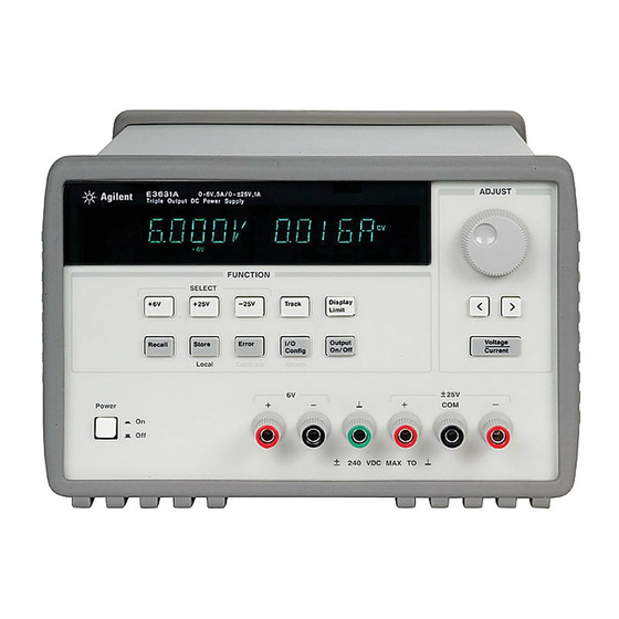
Page 3: The Front Panel At A Glance
The Front Panel at a Glance 1 Meter and adjust selection keys 7 I/O Configuration / Secure key 2 Tracking enable/disable key 8 Output On/Off key 3 Display limit key 9 Control knob 4 Recall operating state key 10 Resolution selection keys 5 Store operating state / Local key 11 Voltage/current adjust selection key 6 Error / Calibrate key... - Page 4 1 Meter and adjust selection keys Select the output voltage and current of any one supply (+6V, +25V, or -25V output) to be monitored on the display and allow knob adjustment of that supply. ± 2 Tracking enable / disable key Enables / disables the track mode of 25V supplies.
- Page 5 N o t e All front panel keys and controls can be disabled with remote interface commands. The Agilent E3631A must be in "Local" mode for the front panel keys and controls to function.
-
Page 6: Display Annunciators
Display Annunciators Adrs Power supply is addressed to listen or talk over a remote interface. Power supply is in remote interface mode. Displays the output voltage and current for +6V supply. Knob is active for 6V supply. +25V Displays the output voltage and current for +25V supply. Knob is active for +25V supply. -
Page 7: The Rear Panel At A Glance
The Rear Panel at a Glance 1 Power-line voltage setting 4 Power-line module 2 Power-line fuse-holder assembly 5 GPIB (IEEE-488) interface connector 3 AC inlet 6 RS-232 interface connector Use the front-panel key to: I/O Config • Select the GPIB or RS-232 interface (see chapter 3 in User's Guide). •... - Page 8 Theory of Operation Chapter 4 describes block and circuit level theory related to the operation of the power supply. Service Chapter 5 provides guidelines for returning your power supply to Agilent Technologies for servicing, or for servicing it yourself. Component Locator Diagrams Chapter 6 contains the component locator diagrams.
-
Page 9: Environmental Conditions
Environmental Conditions This instrument is designed for indoor use and in an area with low condensation. The table below shows the general environmental requirements for this instrument. Environmental condition Requirements Temperature Operating condition • 0 °C to 40 °C Storage condition •... - Page 10 THIS PAGE HAS BEEN INTENTIONALLY LEFT BLANK.
-
Page 11: Table Of Contents
Chapter 3 Calibration Procedures Agilent Technologies Calibration Services - - - - - - - - - - - - - - - - - 43 Calibration Interval - - - - - - - - - - - - - - - - - - - - - - - - - - - - - - - - - 43... - Page 12 Aborting a Calibration in Progress - - - - - - - - - - - - - - - - - - - - - - - 75 Calibration Record for Agilent E3631A - - - - - - - - - - - - - - - - - - - 76...
- Page 13 Contents Unit Fails Self-Test - - - - - - - - - - - - - - - - - - - - - - - - - - - - - - - 101 Bias Supplies Problems - - - - - - - - - - - - - - - - - - - - - - - - - - - - 102 Self-Test Procedures - - - - - - - - - - - - - - - - - - - - - - - - - - - - - - - 103 Power-On Self-Test - - - - - - - - - - - - - - - - - - - - - - - - - - - - - - - 103 Complete Self-Test - - - - - - - - - - - - - - - - - - - - - - - - - - - - - - - 103...
- Page 14 Contents THIS PAGE HAS BEEN INTENTIONALLY LEFT BLANK.
-
Page 15: Chapter 1 Specifications
Specifications... -
Page 16: Specifications
Specifications The performance specifications are listed in the following pages. Specifications are warranted in the temperature range of 0 to 40°C with a resistive load. Supplemental characteristics, which are not warranted but are descriptions of performance determined either by design or testing. Chapter 3 "Calibration Procedures" contains procedures for verifying the performance specifications. -
Page 17: Performance Specifications
Chapter 1 Specifications Performance Specifications Performance Specifications Output Ratings (@ 0°C - 40°C) +6V Output 0 to +6 V ; 0 to 5 A +25V Output 0 to +25 V ; 0 to 1 A -25V Output 0 to -25 V ; 0 to 1 A ±... - Page 18 Chapter 1 Specifications Performance Specifications Programming Resolution +6V Output +25V Output -25V Output Voltage 0.5 mV 1.5 mV 1.5 mV Current 0.5 mA 0.1 mA 0.1 mA Readback Resolution +6V Output +25V Output -25V Output Voltage 0.5 mV 1.5 mV 1.5 mV Current 0.5 mA...
-
Page 19: Supplemental Characteristics
Chapter 1 Specifications Supplemental Characteristics Supplemental Characteristics Output Programming Range (maximum programmable values) +6V Output +25V Output -25V Output Voltage 0 to 6.18 V 0 to 25.75 V 0 to -25.75 V Current 0 to 5.15 A 0 to 1.03 A 0 to 1.03 A ±... - Page 20 Chapter 1 Specifications Supplemental Characteristics Cooling Fan cooled Operating Temperature 0 to 40°C for full rated output. At higher temperatures, the output current is derated linearly to 50% at 55°C maximum temperature. Output Voltage Overshoot During turn-on or turn-off of ac power, output plus overshoot will not exceed 1 V if the output control is set to less than 1 V.
- Page 21 Chapter 1 Specifications Supplemental Characteristics Figure 1-1. Dimensions of Agilent E3631A Power Supply...
- Page 22 Chapter 1 Specifications Supplemental Characteristics THIS PAGE HAS BEEN INTENTIONALLY LEFT BLANK.
-
Page 23: Chapter 2 Quick Start
Quick Start... -
Page 24: Quick Start
Quick Start One of the first things you will want to do with your power supply is to become acquainted with its front panel. Written procedures in this chapter prepare the power supply for use and familiarize you with most front-panel operations. •... -
Page 25: To Prepare The Power Supply For Use
(see the next page for detailed information). For 100 or 115 Vac operation, the correct fuse is 2.5 AT (Agilent part number 2110-0913) and for 230 Vac operation, the correct fuse is 2 AT (Agilent part number 2110-0587). - Page 26 Chapter 2 Quick Start To prepare the power supply for use 1 Remove the power cord. Remove 2 Install the corect line fuse. Remove the fuse-holder assembly with a flat- the power-line voltage selector from blade screwdriver from the rear the power-line module.
-
Page 27: To Check The Rated Voltages Of The Power Supply
Chapter 2 Quick Start To check the rated voltages of the power supply To check the rated voltages of the power supply The following procedures check to ensure that the power supply develops its rated voltage outputs with no load and properly responds to operation from the front panel. For each step, use the keys shown on the left margins. - Page 28 Chapter 2 Quick Start To check the rated voltages of the power supply +25V 5 Check the voltage function for the +25V supply. Select the meter and adjust selection key for the +25V supply. The CV annunciator is still lit and the +25V annunciator will turn on. Repeat steps (3) and (4) to check the voltage function for the +25V supply.
-
Page 29: To Check The Rated Currents Of The Power Supply
Chapter 2 Quick Start To check the rated currents of the power supply To check the rated currents of the power supply The following procedures check to ensure that the power supply develops its rated current outputs with a short and properly responds to operation from the front panel. For each step, use the keys shown on the left margin. - Page 30 Chapter 2 Quick Start To check the rated currents of the power supply 6 Ensure that the current can be adjusted from zero to the maximum rated value. Adjust the knob until the ammeter indicates 0 amps and then until the ammeter indicates 5.0 amps.
-
Page 31: To Use The Power Supply In Constant Voltage Mode
Chapter 2 Quick Start To use the power supply in constant voltage mode To use the power supply in constant voltage mode To set up the power supply for constant voltage (CV) operation, proceed as follows. For each step, use the keys shown on the left margin. 1 Connect a load to the desired output terminals. - Page 32 Chapter 2 Quick Start To use the power supply in constant voltage mode Vol/Cur 5 Adjust the knob for the desired current limit. Check that the Lmt annunciator still blinks. Set the knob for current control. The second digit of ammeter will be blinking. Adjust the knob to the desired current limit. Vol/Cur 6 Adjust the knob for the desired output voltage.
-
Page 33: To Use The Power Supply In Constant Current Mode
Chapter 2 Quick Start To use the power supply in constant current mode To use the power supply in constant current mode To set up the power supply for constant current (CC) operation, proceed as follows. For each step, use the keys shown on the left margin. 1 Connect a load to the output terminals of the desired supply. - Page 34 Chapter 2 Quick Start To use the power supply in constant current mode 5 Adjust the knob for the desired voltage limit. Check that the knob is still selected for voltage control and the Lmt annunciator blinks. Adjust the knob for the desired voltage limit. Vol/Cur 6 Adjust the knob for the desired output current.
-
Page 35: To Use The Power Supply In Track Mode
Chapter 2 Quick Start To use the power supply in track mode To use the power supply in track mode The ±25V supplies provide 0 to ±25 V tracking outputs. In the track mode, two voltages of the ±25V supplies track each other to within ±(0.2% of output + 20 mV) for convenience in varying the symmetrical voltages needed by operational amplifiers and other circuits using balanced positive and negative inputs. -
Page 36: To Store And Recall The Instrument State
Chapter 2 Quick Start To store and recall the instrument state To store and recall the instrument state You can store up to three different operating states in non-volatile memory. This also enables you to recall the entire instrument state with just a few key presses from the front panel. - Page 37 Chapter 2 Quick Start To store and recall the instrument state Store 4 Save the operating state. The operating state is now stored. To recall the stored state, go to the following steps. DONE This message appears on the display for approximately 1 second. Recall 5 Turn on the recall mode.
-
Page 38: To Rack Mount The Power Supply
Option 1CM (P/N 5062-3957). Installation instructions and hardware are included with each rack-mounting kit. Any Agilent Technologies System II instrument of the same size can be rack-mounted beside the Agilent E3631A power supply. To rack mount the power supply, follow these procedures. - Page 39 Chapter 2 Quick Start To rack mount the power supply To rack mount two instruments of the same depth side-by-side, order lock-link kit 5061-9694 and flange kit 5063-9214. To install two instruments in a sliding support shelf, order suport shelf 5063- 9256, and slide kit 1494-0015.
- Page 40 Chapter 2 Quick Start To rack mount the power supply THIS PAGE HAS BEEN INTENTIONALLY LEFT BLANK.
-
Page 41: Chapter 3 Calibration Procedures
Calibration Procedures... -
Page 42: Calibration Procedures
• Measurement Techniques, page 47 • Constant Voltage (CV) Verifications, page 50 • Constant Current (CC) Verifications, page 58 • Performance Test Record for Agilent E3631A, page 63 • Calibration Security Code, page 65 • Calibration Count, page 69 • Calibration Message, page 69 •... -
Page 43: Agilent Technologies Calibration Services
Agilent Technologies Calibration Services When your power supply is due for calibration, contact your local Agilent Technologies Service Center for a low-cost calibration. The Agilent E3631A power supply is supported on calibration processes which allow Agilent Technologies to provide this service at competitive prices. -
Page 44: Automating Calibration Procedures
The power supply must be unsecured prior to initiating the calibration procedure. An Agilent BASIC program for calibration over the GPIB interface is listed at the end of this chapter. -
Page 45: Test Considerations
Chapter 3 Calibration Procedures Test Considerations Test Considerations To ensure proper instrument operation, verify that you have selected the correct power-line voltage prior to attempting any test procedure in this chapter. See page 26 in chapter 2 for more information. •... -
Page 46: Performance Verification Tests
5 seconds. The complete self-test will be Recall finished in 2 more seconds. You can also perform a self-test from the remote interface (see chapter 3 in the Agilent E3631A User's Guide). • If the self-test is successful, "PASS" is displayed on the front panel. -
Page 47: Measurement Techniques
Chapter 3 Calibration Procedures Measurement Techniques Measurement Techniques Setup for Most Tests Most tests are performed at the front terminals as shown in the following figure. Measure the dc voltage directly at the (+) and (-) terminals on the front panel. Figure 3-1. -
Page 48: General Measurement Techniques
Chapter 3 Calibration Procedures Measurement Techniques General Measurement Techniques To achieve best results when measuring load regulation, peak-to-peak voltage, and transient response time of the power supply, measuring devices must be connected through the hole in the neck of the binding post at (A) while the load resistor is plugged into the front of the output terminals at (B). -
Page 49: Current-Monitoring Resistor
The test procedures are written assuming that you know how to program the power supply either from the front panel or from an GPIB or RS-232 controller. Complete instructions on front panel and remote programming are given in the Agilent E3631A User's Guide. -
Page 50: Constant Voltage (Cv) Verifications
Chapter 3 Calibration Procedures Constant Voltage (CV) Verifications Constant Voltage (CV) Verifications Constant Voltage Test Setup If more than one meter or a meter and an oscilloscope are used, connect each to the (+) and (-) terminals by a separate pair of leads to avoid mutual coupling effects. Use coaxial cable or shielded 2-wire cable to avoid noise pick-up on the test leads. - Page 51 Chapter 3 Calibration Procedures Constant Voltage (CV) Verifications 5 Readback the output voltage of the selected output over the remote interface by sending the command: MEAS:VOLT? {P6V|P25V|N25V} 6 Record the value displayed on the controller. This value should be within the limits specified below for each output tested.
-
Page 52: Cv Load Regulation
Chapter 3 Calibration Procedures Constant Voltage (CV) Verifications CV Load Regulation This test measures the immediate change in the output voltage resulting from a change in the output current from full to no load. 1 Turn off the power supply and connect a digital voltmeter between the (+) and (-) terminals of the output to be tested as shown in Figure 3-1. -
Page 53: Cv Line Regulation
Chapter 3 Calibration Procedures Constant Voltage (CV) Verifications CV Line Regulation This test measures the immediate change in output voltage that results from a change in ac line voltage from the minimum value (10% below the nominal input voltage) to maximum value (10% above the nominal input voltage). -
Page 54: Normal Mode Voltage Noise (Cv Ripple And Noise)
Chapter 3 Calibration Procedures Constant Voltage (CV) Verifications Normal Mode Voltage Noise (CV Ripple and Noise) The normal mode voltage noise is in the form of ripple related to the line frequency plus some random noise. The normal mode voltage noise is specified as the RMS or peak-to-peak output voltage in a frequency range from 20 Hz to 20 MHz. - Page 55 Chapter 3 Calibration Procedures Constant Voltage (CV) Verifications Figure 3-3. Peak-to-Peak Ripple/Noise Measurement Setup Figure 3-4. RMS Ripple/Noise Measurement Setup...
-
Page 56: Common Mode Current Noise
Chapter 3 Calibration Procedures Constant Voltage (CV) Verifications Common Mode Current Noise The common mode current is that ac current component which exists between any or all outputs or output lines and chassis ground. Common mode noise can be a problem for very sensitive circuitry that is referenced to earth ground. -
Page 57: Load Transient Response Time
Chapter 3 Calibration Procedures Constant Voltage (CV) Verifications Load Transient Response Time This test measures the time for the output voltage to recover to within 15 mV of nominal output voltage following a load change from full load to half load, or half load to full load. -
Page 58: Constant Current (Cc) Verifications
Chapter 3 Calibration Procedures Constant Current (CC) Verifications Constant Current (CC) Verifications Constant Current Test Setup Follow the general setup instructions in the "Measurement Techniques" section starting on page 47 and the specific instructions will be given in the following paragraphs. - Page 59 Chapter 3 Calibration Procedures Constant Current (CC) Verifications 5 Readback the output current from the selected output over the remote interface by sending the command: MEAS:CURR? {P6V|P25V|N25V} 6 Record the value displayed on the controller. This value should be within the limits specified below for each output tested.
-
Page 60: Cc Load Regulation
Chapter 3 Calibration Procedures Constant Current (CC) Verifications CC Load Regulation This test measures the immediate change in output current resulting from a change in the load from full rated output voltage to short circuit. 1 Turn off the power supply and connect the output to tested as shown in Figure 3-1 with the digital voltmeter connected across the 0.1 current monitoring resistor (R Ω... -
Page 61: Cc Line Regulation
Chapter 3 Calibration Procedures Constant Current (CC) Verifications CC Line Regulation This test measures the immediate change in output current that results from a change in ac line voltage from the minimum value (10% below the nominal input voltage) to the maximum value (10% above nominal voltage). -
Page 62: Normal Mode Current Noise (Cc Ripple And Noise)
Chapter 3 Calibration Procedures Constant Current (CC) Verifications Normal Mode Current Noise (CC Ripple and Noise) The normal mode current noise is specified as the rms output current in a frequency range 20 Hz to 20 MHz with the power supply in constant current operation. 1 Turn off the power supply and connect the output to be tested as shown in Figure 3-1 with a load resistor (1.2Ω... -
Page 63: Performance Test Record For Agilent E3631A
Chapter 3 Calibration Procedures Performance Test Record for Agilent E3631A Performance Test Record for Agilent E3631A CV Performance Test Record Specifications Actual Test Description Result Upper Limit Lower Limit CV Programming Accuracy @ 0 volts (DVM reading) +0.0050 V -0.0050 V +6V supply +0.0200 V... -
Page 64: Cc Performance Test Record
Chapter 3 Calibration Procedures Performance Test Record for Agilent E3631A CC Performance Test Record Specifications Actual Test Description Result Upper Limit Lower Limit CC Programming Accuracy @ 0 amps (I +6V supply +0.0100 A -0.0100 A +25V supply +0.0040 A -0.0040 A... -
Page 65: Calibration Security Code
Chapter 3 Calibration Procedures Calibration Security Code Calibration Security Code This feature allows you to enter a security code (electronic key) to prevent accidental or unauthorized calibrations of the power supply. When you first receive your power supply, it is secured. Before you can calibrate the power supply, you must unsecure it by entering the correct security code. -
Page 66: To Unsecure The Power Supply For Calibration
Chapter 3 Calibration Procedures Calibration Security Code To Unsecure the Power Supply for Calibration The power supply can use a calibration security code to prevent unauthorized or accidental calibration. This procedure shows you how to unsecure the power supply for calibration from the front panel. Calibrate Power 1 Turn on the front-panel calibration mode. - Page 67 Chapter 3 Calibration Procedures Calibration Security Code 4 Unsecure the power supply. Secure UNSECURED The power supply is unsecured when you press the key. You will see the Secure above message from the front panel for one second. The "CAL MODE" message is displayed on the front panel after above message.
-
Page 68: To Unsecure The Power Supply Without The Security Code
Chapter 3 Calibration Procedures Calibration Security Code To Unsecure the Power Supply Without the Security Code To unsecure the power supply without the correct security code (when you forget the security code), follow the steps below. See "Electrostatic Discharge (ESD) Precautions"... -
Page 69: Calibration Count
Chapter 3 Calibration Procedures Calibration Count Calibration Count The calibration count feature provides an independent "serialization" of your calibrations. You can determine the number of times that your power supply has been calibrated. By monitoring the calibration count, you can determine whether an unauthorized calibration has been performed. -
Page 70: General Calibration/Adjustment Procedure
Chapter 3 Calibration Procedures General Calibration/Adjustment Procedure General Calibration/Adjustment Procedure The calibration procedures from the front panel are described in this section. For output voltage calibration, disconnect all loads from the power supply and connect a DVM across the output terminals to be calibrated. For output current calibration, disconnect all loads from the power supply, connect an appropriate current monitoring resistor across the output terminals to be calibrated, and connect a DVM across the terminals of the monitoring resistor. - Page 71 Chapter 3 Calibration Procedures General Calibration/Adjustment Procedure To calibrate the output voltages and currents of the power supply from the front panel, proceed as follows: 1 Unsecure the power supply. To calibrate the output voltage and current, you must unsecure the power supply according to the procedure given on page 66.
- Page 72 Chapter 3 Calibration Procedures General Calibration/Adjustment Procedure 7 Pressing the "Calibrate" key saves the change and selects the second voltage Calibrate calibration point for the +6V supply. V HI +5.7000 V If the entered number is within an acceptable range, an "ENTERED" message appears for one second.
- Page 73 Chapter 3 Calibration Procedures General Calibration/Adjustment Procedure 10 Select the first current calibration point for the +6V supply. Calibrate I LO +0.100 A The display shows the first current calibration point for the +6V supply. 11 Read the DVM and change the first current value on the display to match the ÷...
- Page 74 Chapter 3 Calibration Procedures General Calibration/Adjustment Procedure 13 Read the DVM and change the second current value on the display to match the ÷ computed current (DVM reading by shunt resistance). For example, if the computed value is 4.999 A, adjust the current to 4.999 A using the knob and arrow keys.
-
Page 75: Aborting A Calibration In Progress
Chapter 3 Calibration Procedures Aborting a Calibration in Progress Aborting a Calibration in Progress Sometimes it may be necessary to abort a calibration after the procedure has already been initiated. You can abort a calibration at any time by turning the power supply off from the front panel. -
Page 76: Calibration Record For Agilent E3631A
Chapter 3 Calibration Procedures Calibration Record for Agilent E3631A Calibration Record for Agilent E3631A Supply Measurement Step Calibration Description being Mode (DVM) Adjusted Unsecure the power supply (see page 66). Turn on "CAL MODE"(simultaneously press "Calibrate" and "Power" keys) until a beep is heard. -
Page 77: Error Messages
Error Messages Error Messages The following tables are abbreviated lists of error messages for the E3631A. The errors listed are the most likely errors to be encountered during calibration and adjustment. A more complete list of error messages and descriptions is contained in chapter 5 of the E3631A User's Guide. - Page 78 Chapter 3 Calibration Procedures Error Messages Self-Test Error Messages Error Error Message Front panel does not respond RAM read/write failed A/D sync stuck A/D slope convergence failed Cannot calibrate rundown gain Rundown gain out of range Rundown too noisy Serial configuration readback failed System ADC test failed Unable to sense line frequency I/O processor does not respond...
-
Page 79: Calibration Program
! This program makes software adjustments to the E3631A on the GPIB bus ! using an Agilent 34401A and a current shunt. In the program a 0.01 ohm ! current shunt is used to measure current. Be sure to change the value of ! the variable ’Current_shunt’... - Page 80 Chapter 3 Calibration Procedures Calibration Program ...continued PRINT TABXY(10,10),"*************************************************" PRINT TABXY(10,11)," Using the annunciator, note the output selected." PRINT TABXY(10,12)," Connect the selected output to the DMM. Observe" PRINT TABXY(10,13)," Polarity." PRINT TABXY(10,14),"*************************************************" PRINT TABXY(10,15),"Press ’C’ to continue, or ’E’ to Exist, then" PRINT TABXY(10,16),"press ’Enter’"...
- Page 81 Chapter 3 Calibration Procedures Calibration Program ...continued PRINT TABXY(10,9),"***************************************************" PRINT TABXY(10,10)," Connect a CURRENT SHUNT to the Dmm for measuring" PRINT TABXY(59,10)," current." PRINT TABXY(10,11)," Using the annunciator, note the output selected." PRINT TABXY(10,12)," Connect the selected output to the shunt. Observe" PRINT TABXY(60,12),"...
- Page 82 Chapter 3 Calibration Procedures Calibration Program THIS PAGE HAS BEEN INTENTIONALLY LEFT BLANK.
-
Page 83: Chapter 4 Theory Of Operation
Theory of Operation... -
Page 84: Theory Of Operation
It is assumed in the following discussions that you are familiar with the operating and programming instructions presented in the E3631A User's Guide. Subjects covered include the following: •... -
Page 85: Block Diagram Overview
Chapter 4 Theory of Operation Block Diagram Overview Block Diagram Overview This discussion pertains to the block diagram on the next page. The power supply's circuitry is divided into two major blocks: the floating circuitry and the ground referenced circuitry. All power mesh and control circuits, display circuit, and digital circuits are contained in the floating circuitry. -
Page 86: Block Diagram
Chapter 4 Theory of Operation Block Diagram Overview Block Diagram EARTH FLOATING CIRCUITRY REFERENCED CIRCUITRY... -
Page 87: Ac Input And Bias Supplies
Chapter 4 Theory of Operation AC Input and Bias Supplies AC Input and Bias Supplies The ac mains are connected by a fused power module. This module incorporates the functions of mains connection, fusing, and line voltage selection (100/115/230 Vac). The line voltage selection function of the module selects which primary winding of power transformer is energized. -
Page 88: Floating Logic
Chapter 4 Theory of Operation Floating Logic Floating Logic The floating common logic controls operation of the entire instrument. All output functions and bus command interpretation is performed in the main controller U17. The front panel and the earth referenced logic operate as slaves to U17. The floating common logic is comprised of the main controller U17, custom gate array U16, the program ROM U14, RAM U15, calibration EEPROM U18, and the 12 MHz clock oscillator Y1 on the top board . - Page 89 Chapter 4 Theory of Operation Floating Logic M bits/second for the DAC system and 93.75 k bits/second for communication with the front panel controller. The general serial interface is a 3-bit interface as shown below. U18 Internal Signal Configuration Signals Front Panel Signals Serial Clock SERCK...
-
Page 90: D-To-A Converter
Chapter 4 Theory of Operation D-to-A Converter D-to-A Converter All reference voltages of power circuits are derived from the internal voltage reference of system DAC U12 on the top board. The system DAC track/hold amplifier outputs are used to provide controllable reference voltages to three power circuits. The system DAC is programmed and responds to the main controller via internal 3-wire serial data bus SERCLK, SERRBK, and SERSTB. -
Page 91: A-To-D Converter
U5, resistors (R5, R4, R15 and R16), voltage reference (U3A and U3B), ADC controller U16, and residue ADC U17 on the top board. The ADC method used by the Agilent E3631A is called multislope III. Multislope III is a charge balancing continuously integrating analog-to-digital converter. The input voltage continuously forces charge onto the integrator capacitors C18 and C19 through R15 on the top board. -
Page 92: Power Mesh And Control
Chapter 4 Theory of Operation Power Mesh and Control Power Mesh and Control For the ±25V power mesh and control circuit, a preregulator is added ahead of the series pass transistor to minimize the power dissipated in the series pass transistor by controlling the dc level across the input filter capacitor, depending on the output voltage. - Page 93 Chapter 4 Theory of Operation Power Mesh and Control Two error amplifiers are included in a CV/CC supply, one for controlling output voltage, the other for controlling output current. Since the constant voltage amplifier tends to achieve zero output impedance and alters the output current whenever the load resistance changes, while the constant current amplifier causes the output impedance to be infinite and changes the output voltage in response to any load resistance change, it is obvious that the two amplifiers can not operate simultaneously.
-
Page 94: Earth-Referenced Logic
Chapter 4 Theory of Operation Earth-Referenced Logic Earth-Referenced Logic Microprocessor U10 on the bottom board handles GPIB (IEEE-488) control through bus interface chip U8 and bus receiver/driver chips U6 and U7 on the bottom board. The RS-232 interface is also controlled through microprocessor U10. RS-232 transceiver chip U12 on the bottom board provides the required level shifting to approximate ±9 volt logic levels through on-chip charge-pump power supplies using C11 and C12 on the bottom board. - Page 95 Service...
- Page 96 Service This chapter discusses the procedures involved for returning a failed power supply to Agilent Technologies for service or repair. Subjects covered include the following: • Operating Checklist, page 97 • Types of Service Available, page 98 • Repacking for Shipment, page 99 •...
-
Page 97: Chapter 5 Service Operating Checklist
Chapter 5 Service Operating Checklist Operating Checklist Before returning your power supply to Agilent Technologies for service or repair check the following items: Is the Power Supply Inoperative? Verify that the ac power cord is connected to the power supply. -
Page 98: Types Of Service Available
3-year warranty period. You will not be billed for the replacement unit as long as the failed unit is received by Agilent Technologies. • If your 3-year warranty has expired, Agilent will bill you for the Agilent E3631A exchange price - less than a new unit price. Agilent warrants exchange units against... -
Page 99: Repacking For Shipment
A shipping label will be supplied. Agilent will notify you when your failed unit has been received. If the instrument is to be shipped to Agilent Technologies for service or repair, be sure • Attach a tag to the power supply identifying the owner and indicating the required service or repair. -
Page 100: Electrostatic Discharge (Esd) Precautions
(see page 26). For 100 or 115 Vac operation, you must use a 2.5 AT slow- blow fuse (Agilent part number 2110-0913). For 230 Vac operation, you must use a 2 AT slow-blow fuse (Agilent part number 2110-0587). -
Page 101: Troubleshooting Hints
Chapter 5 Service Troubleshooting Hints Troubleshooting Hints This section provides a brief check list of common failures. Before troubleshooting or repairing the power supply, make sure that the failure is in the instrument rather than any external connections. Also make sure that the instrument is accurately calibrated. -
Page 102: Bias Supplies Problems
Chapter 5 Service Troubleshooting Hints Bias Supplies Problems Check that the input to the voltage regulators of the bias supplies is at least 1 V greater than their output. Circuit failures can cause heavy loads of the bias supplies which may pull down the regulator output voltages. -
Page 103: Self-Test Procedures
Chapter 5 Service Self-Test Procedures Self-Test Procedures Power-On Self-Test Each time the power supply is powered on, a set of self-tests are performed. These tests check that the minimum set of logic and measurement hardware are functioning properly. The power-on self-test performs checks 601 through 604 and 624 through 634. - Page 104 Chapter 5 Service Self-Test Procedures Cannot calibrate rundown gain This test checks the nominal gain between integrating ADC and the U17 on-chip ADC. This error is reported if the procedure can not run to completion due to a hardware failure. Rundown gain out of range This test checks the nominal gain between the integrating ADC and the U17 on-chip ADC.
- Page 105 Chapter 5 Service Self-Test Procedures System DAC test failed This test checks if the DAC hardware is functional. The main controller U17 (U10 for serial MY53xx6xxx) sends a reference voltage data to DAC and converts the DAC output to digital data to see if the digital data is within a valid range.
- Page 106 Chapter 5 Service Self-Test Procedures THIS PAGE HAS BEEN INTENTIONALLY LEFT BLANK.
- Page 107 Component Drawings...
- Page 108 Component Drawings This chapter contains component drawings for the power supply. The block diagram is also shown in chapter 4. • E3631-60002 Component Locator for the Main Board — Top, on page 109 • E3631-60003 Component Locator for the Front Panel, on page 110 •...
-
Page 109: Chapter 6 Component Drawings E3631-60002 Component Locator For The Main Board - Top
Chapter 6 Component Drawings E3631-60002 Component Locator for the Main Board — Top E3631-60002 Component Locator for the Main Board — Top... -
Page 110: E3631-60003 Component Locator For The Front Panel
Chapter 6 Component Drawings E3631-60003 Component Locator for the Front Panel E3631-60003 Component Locator for the Front Panel... -
Page 111: E3631-60004 Component Locator For The Main Board - Bottom
Chapter 6 Component Drawings E3631-60004 Component Locator for the Main Board — Bottom E3631-60004 Component Locator for the Main Board — Bottom... -
Page 112: Component Locator For The Main Board - Top (Serial My53Xx6Xxx)
Chapter 6 Component Drawings Component Locator for the Main Board — Top (serial MY53xx6xxx) Component Locator for the Main Board — Top (serial MY53xx6xxx) -
Page 113: Component Locator For The Front Panel (Serial My53Xx6Xxx)
Chapter 6 Component Drawings Component Locator for the Front Panel (serial MY53xx6xxx) Component Locator for the Front Panel (serial MY53xx6xxx) -
Page 114: Component Locator For The Main Board - Bottom (Serial My53Xx6Xxx)
Chapter 6 Component Drawings Component Locator for the Main Board — Bottom (serial MY53xx6xxx) Component Locator for the Main Board — Bottom (serial MY53xx6xxx) - Page 115 To the extent allowed by local contain additional information to equipment or permanent ification or misuse, operation law, Agilent shall not be liable and replacement pages which loss of data. outside of the environmental for errors contained herein or you merge into the manual.
-
Page 116: Agilent Technologies
Product specifications and descriptions in this document are subject to change without notice. Always refer to the English version at the Agilent Web site for the latest revision. © Agilent Technologies, Inc. 2000–2013 Twelfth Edition, October 25, 2013 E3631A-90011...