Table of Contents
Advertisement
Quick Links
Advertisement
Table of Contents

Related Manuals for Ariston BOOSTER


Summary of Contents for Ariston BOOSTER
- Page 1 Scaldacqua Elettrico Rapido Rapido Rapid Rapid electric water heater Rapide Chauffe-eau Electrique Rapide Merloni TermoSanitari SpA Viale Aristide Merloni, 45 60044 Fabriano (AN) Elektrischer Wasserdurchlauferhitzer Tel. 0732.6011 Telefax. 0732.602331 Telex 560160 http://www.mts.it...
- Page 2 ARISTON products measure up to the confidence placed in them by families all over the world. BOOSTER has been designed for the person who, just like you, demands maximum performance. hanks to the exclusive BOOSTER dual heating...
-
Page 3: Table Of Contents
CONTENTS 1 HOW TO REMOVE THE PACKAGING ..............19 2 DESCRIPTION OF THE SYSTEM ................20 Accessories supplied withthe heater 3 TECHNICAL CHARACTERISTICS ................21 Rating plate data Technical data ..................22 Dimensions 4 GENERAL WARNINGS ..................... 24 5 INSTALLATION .................... -
Page 4: How To Remove The Packaging
HOW TO REMOVE THE PACKAGING Operations that must be carried out by at least 2 people. NSTRUCTION ANDBOOK First place the box in the position Hold the box on both sides and shown in the diagram and open it. Then carefully turn it upside down. -
Page 5: Description Of The System
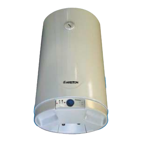
DESCRIPTION OF THE SYSTEM Adjustment knob Control panel Cover 1/2" G hot water 1/2" G cold water inlet outlet Sector Voltage feed plug and cable Rating plate BO0299-010 The water heaters are equipped with water intake and outlet connections at the bottom. 2.1 A CCESSORIES SUPPLIED WITH THE HEATER Safety valve... -
Page 6: Technical Characteristics
(about 20 ÷ 30% of the total capacity) in a shorter time thus reducing consumption. Use the “BOOSTER” key for this function. BO0299-020 The temperature in area H is preset to the maximum thermostat temperature setting and is controlled by means of the changeover switch thermostat probe 7. -
Page 7: Technical Data
3.2 T ECHNICAL DATA 1 0 0 M O D E L CAPACITY APPLIANCE WEIGHT kg (N) 25,5 (255) 31 (310) "BOOSTER" HEATING TIME 1,00 1,10 ( T = 45 °C) h, min 1640 1640 "BOOSTER" power "NORMAL" TOTAL HEATING TIME... - Page 8 ONNECTION IAGRAM 3 2 1 NORMAL BOOSTER LECTRICAL WIRING DIAGRAM Red warning light BOOSTER Red warning light NORMAL Upper green warning light Upper heating + °C element Changeover switch Changeover thermostat 2 (C) switch Lower heating element Operational Lower green...
-
Page 9: General Warnings
GENERAL WARNINGS National norms may include • electrical wiring must com- the data on the rating plate restrictions on installation in ply with what is specified showing the characteris- bathrooms. Installation is at in paragraph 5.3; tics of the appliance; the purchaser’s expense. -
Page 10: Wiring
If the electricity is cut off to the lower heating element, the amount of hot water available is 20 ÷ 30% of the total capacity ("BOOSTER" running). You should still contact your Technical Assistance Service. -
Page 11: Description Of The Controls
DESCRIPTION OF THE CONTROLS BO0299-040 Upper heating element warning light BOOSTER FUNCTION When the BOOSTER button 4 is pressed, the Lower heating element warning light warning light 5 switches on and the upper heating Adjustment knob element switches on. This function will provide "BOOSTER"... -
Page 12: How To Remove The Cover
8.1 H OW TO REMOVE THE COVER In order to gain access to the electrical part, remove cover E as follows: • unscrew screws A-B-C-D that fasten it; • remove the cover by pulling it downwards as shown in the diagram 18. SEM0510-280 BO0299-090 8.2 H... -
Page 13: 8.3 Regular Maintenance
• Remove screws 8 so that the electrical • Remove the earth screw V. system is disconnected from the water heater. • Use a 13 mm spanner to remove flange • Remove the flange. F check nuts. 8.3 REGULAR MAINTENANCE 8.3.1 H OW TO REMOVE DEPOSITS FROM THE HEATING ELEMENTS For the appliance to perform well, remove any hard water deposits that have formed on... -
Page 14: Water Safety Device
8.3.2 W ATER SAFETY DEVICE The safety valve must be made to work regularly at least once a month. Move the lever up and down several times in order to make sure it is not blocked by scale. 8.4 SPECIAL MAINTENANCE 8.4.1 R EPLACEMENT OF ANODE The magnesium anode 2 must be replaced... - Page 15 Merloni TermoSanitari S.p.A. is not bound by the data and characteristics described in this hand- book and reserves the right to make any modifications it deems necessary, without priornotice or replacement. This appliance complies with the requirements set forth in EMC directive 89/336/EEC concerning the electromagnetic compatibility.