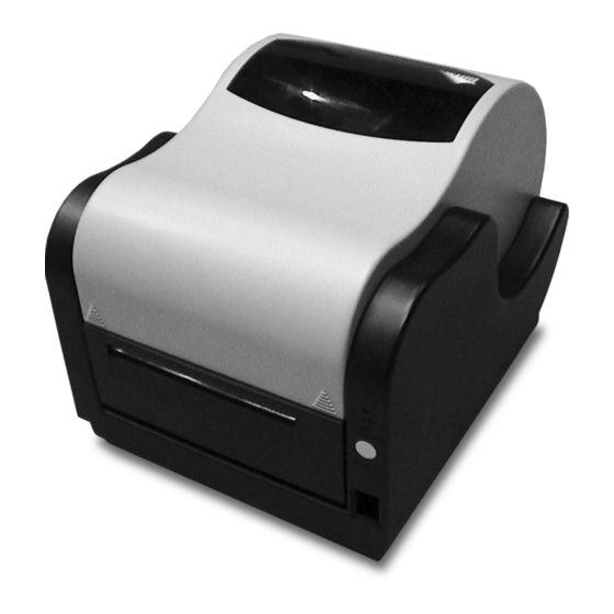
SATO CX400 Service Manual
Desktop printer
Hide thumbs
Also See for CX400:
- Programming reference manual (102 pages) ,
- Operator's manual (26 pages) ,
- Quick start manual (17 pages)
Table of Contents
Advertisement
Advertisement
Table of Contents

Related Manuals for SATO CX400


Summary of Contents for SATO CX400
-
Page 1: Service Manual
CX400 DESKTOP PRINTER SERVICE MANUAL SATO CX400 Service Manual... -
Page 2: Sato Group Of Companies
All rights reserved. This document, nor any part of it, may be reproduced or issued to third parties in any form without the express permission of SATO America, Inc. The material in this document is provided for general information only and is subject to change without notice. SATO America, Inc. -
Page 3: Table Of Contents
Media Index Sensor Calibration Dispenser Sensor Calibration TROUBLESHOOTING Problem Isolation Self-Diagnosis Label MAINTENANCE Cleaning Print Head Replacement Main Circuit Board replacement Platen Roller Replacement TECHNICAL DATA Physical Properties Enviromental Specifications Power requirements Printer Performance Printer Specifications SATO CX-400 Service Manual... - Page 4 TECHNICAL DATA Media Specifications Ribbon Specifications Serial Interface Specifications Regulatory Approvals BLOCK DIAGRAMS System Block Diagram Control Board Block Diagram Panel Board Schematic Sensor Board Schematic Main Board Wiring Diagram SATO CX400 Service Manual...
-
Page 5: General Description
The printer is also designed to use eye-mark or gap-label sensing The CX400 uses a single sensor element for both direct thermal and thermal transfer printing. The printing method may be selected by using configuration settings in the software program or by sending the commands directly to the printer. -
Page 6: Switches And Indicators
Press during pause to feed a blank label or print the duplicate of the prior label. Press to reset the printer to the factory settings. Power Indicator Continuously illuminated when functional. Blinks when a malfunction has occured. Page 1-2 PN 9001110A SATO CX400 Service Manual... -
Page 7: Connection Ports
Also permits PC connection for advanced programming, control, and operation. VAC Power Supply Port Located centrally on the rear of the printer. Permits the connection of the voltage supply transformer. SATO CX400 Service Manual PN 9001110A Page 1-3... - Page 8 Monitors the presence of a label in the dispenser. When the label is removed from the dispenser, the next label will be prompted Print Head Open Sensor Detects when the print assembly is not latched into the print position. Page 1-4 PN 9001110A SATO CX400 Service Manual...
-
Page 9: Operational System
This permits the CPU to reload a program into the on board Flash ROM after complete corruption. The default setting is in the normal position. SATO CX400 Service Manual PN 9001110A Page 1-5... -
Page 10: Accessories Installation
12. Manipulate housing (9) onto base assembly (11) oriented as was removed. 13. Secure housing (9) to base assembly (11) using two screws (10). 14. Plug power switch (8) into the two leads of daughter board. SATO CX400 Service Manual PN 9001110A Page 2-1... - Page 11 19. Ensure print media and ribbon are properly loaded in the printer. 20. Lower the print assembly and latch in position. 21. Close cover, connect power supply cord, and apply power. 22. Send the following command stream to enable: <ESC>A <ESC>CK1 <ESC>Z. Page 2-2 PN 9001110A SATO CX400 Service Manual...
-
Page 12: Dispenser Attachment
The procedure assumes that the unit is without additional attachments that may pose an impediment to sensor installation. CAUTION: Printer electronics are susceptable to static discharge. Ensure appropriate grounding measures are taken before beginning any activity inside the printer. SATO CX400 Service Manual PN 9001110A Page 2-3... - Page 13 5. Remove clips (6) and (7) from the left and right ends of roller shaft (8) respectively. NOTE: Before removing the retaining clips from each end of the roller shaft, it is advised that their orientation be observed and noted. REARVIEW Dispenser Installation, Figure 2-3 Page 2-4 PN 9001110A SATO CX400 Service Manual...
-
Page 14: Font Module
Connect the parallel interface cable supplied with the printer to the computer LPT1 port and the printer parallel port. Place the Firmware upgrade disk in the computer and follow the instructions in the Readme.TXT file. SATO CX400 Service Manual PN 9001110A Page 2-5... - Page 15 3. Enter the MS-DOS mode on the computer. 4. Type “X:SATO” (were X is the location fo the Firmware Upgrade file) at the DOS prompt. 5. Allow 5 minutes for the power and error LED’s to begin blinking in synchronicity.
-
Page 16: Operational Setup
8. Pull media (2) forward and feed it through the discharge slot of cover (5). 9. Lower and press print head assembly into operational position. 10. When the error LED stops blinking, press the feed button to begin printing. SATO CX400 Service Manual PN 9001110A Page 3-1... -
Page 17: Ribbon Loading
NOTE: The coated side has the duller sheen. If still unsure, scratch each side to determine which is coated. NOTE: The ribbon supply spindle is located on the lower side of the print assembly. Page 3-2 PN 9001110A SATO CX400 Service Manual... -
Page 18: Input/Output Connections
If the sensor incorrectly detects the presence of print media available for use, the dispenser sensor may require calibration. Perform the applicable steps below relative to the media type used. SATO CX400 Service Manual PN 9001110A Page 3-3... - Page 19 MIN LABEL PITCH 0.39" (10mm) MIN. LENGTH EYE-MARK ON = 0.59" (15mm) BOTTOM OF LINER LABEL BACKING PAPER INSIDE EDGE LABEL INSIDE EDGE 0.06" (1.5mm) = NON-PRINT Figure 3-3, Label Stock Diagram Page 3-4 PN 9001110A SATO CX400 Service Manual...
-
Page 20: Media Index Sensor Calibration
1. Place a label in the discharge slot over the sensor. 2. Send the following commands to the printer: <ESC>A <ESC>&P0 <ESC>Z. 3. Allow 5 seconds for the printer to complete the process. SATO CX400 Service Manual PN 9001110A Page 3-5... - Page 21 Section 3: Operation Page 3-6 PN 9001110A SATO CX400 Service Manual...
-
Page 22: Troubleshooting
TROUBLESHOOTING The CX400 label printer has integrated systems and performance monitors for instant status output. The red error LED and the green power LED work in conjuction to provide all of the status information required. The following table provides status identification. -
Page 23: Self-Diagnosis Label
On board memory of the total linear length of print activity. This non-resettable feature permits monitoring of component life cycles and warranty validation. Print Speed (6): Identifies the print speed setting. The default speed is 3 ips. Page: 4-2 PN 9001110A SATO CX400 Service Manual... - Page 24 Provides on board non-volatile flash memory for storing graphics, font characters, etc. 512K bytes. Memory Slot 2 (14): Optional on board non-volatile flash memory for storing graphics, font characters, etc. 2M or 4M bytes. Self-Diagnosis Label, Figure 3-1 SATO CX400 Service Manual PN 9001110A Page: 4-3...
- Page 25 Section 4: Troubleshooting Page: 4-4 PN 9001110A SATO CX400 Service Manual...
-
Page 26: Maintenance Cleaning
5. Remove the ribbon from the rewind spool to expose the print head assembly (3). 6. Press downward on the upper right side of the print head assembly (3) and manipulate the unit free. SATO CX400 Service Manual PN 9001110A Page: 5-1... - Page 27 15. Reapply printer ribbon as required and latch print assembly (2) for operation. 16. Close cover (1), connect power supply cord, and switch power on. 17. Test cycle for proper function. Print Head Replacement, Figure 5-1 Page: 5-2 PN 9001110A SATO CX400 Service Manual...
-
Page 28: Main Circuit Board Replacement
If the peeler cover is installed, two screws located at the hinge must be removed. Pull Outward and Lift Here Circuit Board Replacement, Figure 5-2 SATO CX400 Service Manual PN 9001110A Page: 5-3... - Page 29 13. Connect all wiring harnesses to replacement circuit board (11) as was removed. 14. Place printer chassis (9) onto base (7) oriented so that mounting holes are aligned and secure using four screws (8). Circuit Board Replacement, Figure 5-3 Page: 5-4 PN 9001110A SATO CX400 Service Manual...
- Page 30 External Connector JP14 Ribbon Sensor JP15 Eye-Mark Sensor JP24 Gap Sensor JP2-1 Print Head Open Sensor JP16 Panel Board Motor JP18 JP17 JP29 Ground Print Head Daughter Board Circuit Board Replacement, Figure 5-4 SATO CX400 Service Manual PN 9001110A Page: 5-5...
-
Page 31: Platen Roller Replacement
If the peeler cover is installed, two screws located at the hinge must be removed. Platen Roller Replacement, Figure 5-5 Page: 5-6 PN 9001110A SATO CX400 Service Manual... - Page 32 22. Connect power switch (4) to its respective leads and insert into face of housing (5) oriented with the on position up. 23. Lower and latch print assembly (2) into operational position. 24. Close cover (1), connect power supply cord, switch power on, and test cycle. SATO CX400 Service Manual PN 9001110A Page: 5-7...
- Page 33 Section 5: Maintenance Platen Roller Replacement, Figure 5-6 Page: 5-8 PN 9001110A SATO CX400 Service Manual...
-
Page 34: Technical Data
Hitachi SH7034 (16 Bit External, 32 Bit Internal) Integrated CLock 20M Hz (26 MIPS) Panel Features Green Power LED, Red Error LED, Feed Button DRAM Flash ROM Additional Memory 2 or 4 MB Flash ROM SATO CX400 Service Manual PN 9001110A Page 6-1... -
Page 35: Media Specifications
Data Bits 7 or 8 Stop Bits 1 or 2 Default Parameters 9600 Bauds, No Parity, 8 Data Bits, 1 Stop Bit. REGULATORY APPROVALS FCC Class B, CE, TUV, CCC, and UL. Page 6-2 PN 9001110A SATO CX400 Service Manual... -
Page 36: Block Diagrams
(9 pin) Media Sensor Roller Platen Media Sensor Roller Stepping Motor Stepping Motor Print Head Open Sensor Print Head Open Sensor External AC Adaptor External AC Adaptor System Block Diagram, Figure 7-1 SATO CX400 Service Manual PN 9001110A Page 7-1... -
Page 37: Control Board Block Diagram
Motor T. M. (JP4) Thermal Print Head (JP18) Thermal Print Head (JP18) Control Board Block Diagram, Figure 7-2 HEADER 6 HEADER 6 Key1 Key1 power power error error Panel Board Schematic, Figure 7-3 Page 7-2 PN 9001110A SATO CX400 Service Manual... -
Page 38: Sensor Board Schematic
(19 VAC) Adaptor Board Board Board Sensor Sensor (JP1) (19 VAC) Board Board Board Print Head Open Cutter Module Print Head Open Sensor Cutter Module Sensor Main Board Wiring Diagram, Figure 7-5 SATO CX400 Service Manual PN 9001110A Page 7-3... - Page 39 Section 7: Block Diagrams/Schematics Page 7-4 PN 9001110A SATO CX400 Service Manual...