Panasonic AW-HS50N Operating Instructions Manual
Compact live switcher
Hide thumbs
Also See for AW-HS50N:
- Operating instructions manual (125 pages) ,
- Operating instructions manual (140 pages) ,
- Operating instructions manual (68 pages)
Table of Contents
Advertisement
Before operating this product, please read the instructions carefully and save this manual for
future use.
For instructions on how to operate this Compact Live Switcher and how
to establish its settings, refer to the "Operations and Settings" manual
(PDF file) which can be found on the CD-ROM supplied with the camera.
Operating Instructions
Compact Live Switcher
AW-HS50N
Model No.
<Basics>
3TR006512BAA
Advertisement
Table of Contents

Related Manuals for Panasonic AW-HS50N


Summary of Contents for Panasonic AW-HS50N
- Page 1 Operating Instructions <Basics> Compact Live Switcher AW-HS50N Model No. Before operating this product, please read the instructions carefully and save this manual for future use. For instructions on how to operate this Compact Live Switcher and how to establish its settings, refer to the “Operations and Settings” manual (PDF file) which can be found on the CD-ROM supplied with the camera.
-
Page 2: Safety Precautions
Safety precautions CAUTION: CAUTION TO REDUCE THE RISK OF FIRE OR SHOCK RISK OF ELECTRIC SHOCK HAZARD AND ANNOYING INTERFERENCE, DO NOT OPEN USE THE RECOMMENDED ACCESSORIES CAUTION: TO REDUCE THE RISK OF ELECTRIC SHOCK, ONLY. DO NOT REMOVE COVER (OR BACK). NO USER SERVICEABLE PARTS INSIDE. -
Page 3: Important Safety Instructions
Safety precautions IMPORTANT SAFETY INSTRUCTIONS Read these operating instructions carefully before using the unit. Follow the safety instructions on the unit and the applicable safety instructions listed below. Keep these operating instructions handy for future reference. 1) Read these instructions. 10) Protect the power cord form being walked pinched particularly... -
Page 4: Table Of Contents
Contents Before use ............5 2. Preparations ..........18 Overview ................5 2-1. Installation precautions ...........18 2-2. Connections with other devices.......19 Concerning the Operating Instructions ......5 2-2-1. Block diagram...........19 Trademarks and registered trademarks ......5 2-2-2. Example of connections ........20 About copyright and licence ..........5 2-3. -
Page 5: Before Use
violation of export laws of the software provided with this unit are expressly prohibited. Instructions For the purposes of these instructions, AW-HS50N Concerning the ratings is referred to as “AW-HS50”. Similarly, AW-HE50HN and AW-HE50SN are display referred as “AW-HE50,”... -
Page 6: Disclaimer Of Warranty
Network security IN NO EVENT SHALL Panasonic System Networks As you will use this unit connected to a network, your Co., Ltd. BE LIABLE TO ANY PARTY OR ANY attention is called to the following security risks. -
Page 7: Characteristics
Characteristics Compact design Multi view display function The unit features a compact design with its half- One channel is provided for the multi view display rack size width (210 mm [8-1/4˝]) and its 4RU size function. (177 mm [6-15/16˝]) depth. - Page 8 The control panel layout includes a row of five controller using IP connection The unit can be connected to a Panasonic remote crosspoint buttons for the A bus and another row of five crosspoint buttons for the B bus. Using these camera controller using a network.
-
Page 9: Accessories
Accessories Check that the following accessories are present and accounted for. Operating Instructions <Basics> (this manual) ..1 AC adapter ..............1 CD-ROM ..............1 Power cable (2 m [6.6 ft.]) .......... 1 Operating Instructions <Basics> Operating Instructions <Operations and Settings> ... -
Page 10: Operating Precautions
Operating precautions In addition to heeding the points presented in the “Safety precautions”, observe the following precautions as well. Handle carefully. Precaution to be observed during production Do not drop the product, or subject it to strong shock This product’s image switching and image effect or vibration. -
Page 11: Parts And Their Functions
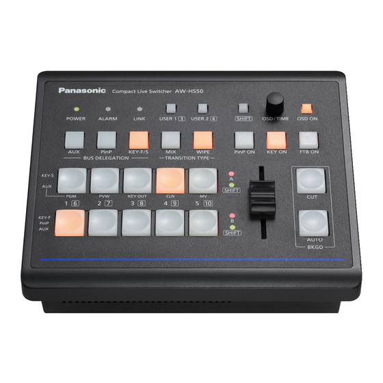
1. Parts and their functions 1-1. Control panel Compact Live Switcher AW-HS50 POWER ALARM LINK USER 1 USER 2 SHIFT OSD/TIME OSD ON PinP KEY-F/S WIPE PinP ON KEY ON FTB ON BUS DELEGATION TRANSITION TYPE KEY-S SHIFT KEY OUT KEY-F PinP SHIFT... - Page 12 1. Parts and their functions USER buttons [USER 1, USER 2] OSD/TIME dial [OSD/TIME] Any four functions selected from among the menu The following operations are performed using this items can be assigned to the USER 1 button and dial.
- Page 13 1. Parts and their functions KEY ON button [KEY ON] AUTO button [BKGD AUTO] This is used to combine key materials for the This automatically initiates the transition for the transition duration which has been set. transition duration which has been set. (Auto transition) Press the button.
- Page 14 1. Parts and their functions MIX button [MIX] BUS DELEGATION buttons This is used to execute transitions (MIX transitions) [AUX, PinP, KEY-F/S] while overlapping the images of the A bus and These are used to select the buses which output B bus (or images of the PGM bus and PST bus).
- Page 15 1. Parts and their functions A bus crosspoint buttons [1 to 5] 2. When the indicator of the AUX button is blinked: B bus crosspoint buttons [1 to 5] When one of the crosspoint buttons is pressed, These are used to select the materials to be output the AUX bus material is selected.
-
Page 16: Rear Panel
1. Parts and their functions 1-2. Rear panel SIGNAL GND POWER SDI OUT SDI IN 12 V DVI OUT DVI IN TALLY / GPI BOOT SV NM SDI IN connectors [SDI IN 1 to 4] POWER switch [POWER] When the POWER switch is set to the ON position, These are the HD/SD SDI signal input connectors. -
Page 17: Cooling Fan
1. Parts and their functions DVI OUT connector [DVI OUT] TALLY/GPI connector [TALLY/GPI] This is the DVI-D signal output connector. (D-sub 15-pin, female, inch thread) Signals with the following resolution can be output This connector features five contact input ports from this connector by menu operations. -
Page 18: Preparations
2. Preparations 2-1. Installation precautions In addition to heeding the points presented in the “Safety precautions”, observe the following precautions as well. Be absolutely sure to ask your dealer to do the jobs of installing and connecting the unit. Connecting the power supply Handle carefully! ... -
Page 19: Connections With Other Devices
2. Preparations 2-2. Connections with other devices 2-2-1. Block diagram AW-HS50 DbyD BLACK SDI IN 1 SDI OUT 1 BKGD TRANS VPrc 1, 2 (CUT, MIX, WIPE) COLOR BKGD DbyD SDI IN 2 Output 1, 2 COLOR VPrc (SDI) INPUT 1 to 4 (LIN, LUM, CHROMA) (SDI) DbyD... -
Page 20: Example Of Connections
2. Preparations 2-2-2. Example of connections HD SDI HD camera HD SDI SDI monitor HD SDI HD SDI HD camera HD SDI HD camera HD SDI SD SDI SDI monitor SD camera DVI-D DVI-D PC monitor SIGNAL GND POWER SDI OUT SDI IN 12 V DVI OUT... - Page 21 2. Preparations Example of IP connections (connecting the unit to the AW-HE50 and AW-RP50) AW-HE50S AW-HE50S LAN cable SDI video signal (straight cable) Monitor 2 Switching hub Monitor 1 LAN cable (straight cable) Monitor Monitor AW-HS50 AW-RP50...
-
Page 22: Turning The Unit's Power On And Off
2. Preparations 2-3. Turning the unit’s power on 2-4. Checking the video output and off Described below are the steps taken to display the unit’s OSD menu on an external monitor to check the Turning on the power unit’s video output. -
Page 23: Displaying The Osd Menus On An Sdi Monitor
2. Preparations Changing the video format 2-4-2. Displaying the OSD menus on an SDI monitor If the OSD menus cannot be displayed even when the SDI monitor has been connected to the unit, the video format must be changed. Connect the SDI monitor to the unit’s Follow the steps below to change the video format. -
Page 24: Osd (On-Screen Display) Menu Operations
2. Preparations Changing the connector for 2-5. OSD (on-screen display) outputting the OSD menus menu operations The unit’s settings are selected using the OSD menus which are displayed on the external monitor. Described here is how to operate the OSD menus. 2-5-1. -
Page 25: Menu Configuration And Moving Between Menus
2. Preparations 2-5-3. Menu configuration and moving between menus Menu configuration of the unit Moving between the main menu and submenus The unit’s OSD menus are organized in two hierarchical levels: the main menu and the submenus. Moving from the main menu to a submenu To select a submenu item: Main menu:... -
Page 26: Operations Using The Submenus
2. Preparations 2-5-4. Operations using the submenus Select the line with the setting item. When the OSD/TIME dial is turned, the cursor “>” at the far left moves up or down. Bring the cursor to the line with the setting item whose setting is to be changed, and then press the OSD/TIME dial. -
Page 27: Indications Used In This Operating Instructions
2. Preparations Move the blinking part. When a setting item has a multiple number of settings, press the OSD/TIME dial to move the blinking part to the right. The blinking part moves This part blinks. Press the OSD/TIME dial. to the right. Complete the changes. -
Page 28: Direct Operations Using The User Buttons And Osd/Time Dial
2. Preparations 2-5-6. Direct operations using the USER buttons and OSD/TIME dial The functions that have been assigned to the USER buttons are displayed in the USER button status display area, and the setting itemes which can be operated directly using the USER buttons and OSD/TIME dial are displayed in the states listed below. -
Page 29: Menu Delegation Function
2. Preparations 2-5-7. Menu delegation function When the buttons listed below are double-clicked, the specified menu is selected. (The menu delegation function) The operation corresponding to the button pressed is also executed. <List of menu delegation functions> Button Menu selected AUTO FTB ON [1] TIME/CBGD Menu... -
Page 30: Appearance
3. Appearance Unit: mm (inch) 189 (7-7/16) 67 (2-5/8) Compact Live Switcher AW-HS50 POWER ALARM LINK USER 1 USER 2 SHIFT OSD/TIME OSD ON PinP KEY-F/S WIPE PinP ON KEY ON FTB ON BUS DELEGATION TRANSITION TYPE KEY-S SHIFT KEY OUT KEY-F PinP SHIFT... -
Page 31: Specifications
4. Specifications Inputs 5 video lines 4 signal lines: SDI IN 1 to SDI IN 4 DVI-D 1 signal line: DVI IN Outputs 3 video lines, 4 outputs 2 signal lines: SDI OUT 1, SDI OUT 2 (Only the SDI OUT 1 signals are split into two) DVI-D 1 signal line: DVI OUT Signal formats 480/59.94i, 576/50i... - Page 32 4. Specifications SDI outputs HD: Serial digital component (SMPTE 292M) SD: Serial digital component (SMPTE 259M) 2 signal lines: SDI OUT 1, SDI OUT 2 (Only the SDI OUT 1 signals are split into two) HD: SMPTE 292M (BTA S-004B) standard complied with •...
- Page 33 4. Specifications Control I/O LAN (RJ-45) Connecting cable: 10BASE-T/100BASE-TX LAN cable (category 5 or above), (For IP control) max. 100 m [328 ft.], STP (Shielded Twisted Pair) cable recommended When connecting to a hub (switching hub), use a straight cable.
- Page 34 © Panasonic System Networks Co., Ltd. 2010 F0610Y1070...
- Page 35 AW-HS50N 3TR006512BAA...
- Page 36 ...
- Page 41 ...
- Page 42 ...
- Page 43 ...
- Page 44 ...
- Page 45 ...
- Page 46 ...
- Page 47 Compact Live Switcher AW-HS50 POWER ALARM LINK USER 1 USER 2 SHIFT OSD/TIME OSD ON PinP KEY-F/S WIPE PinP ON KEY ON FTB ON BUS DELEGATION TRANSITION TYPE KEY-S SHIFT KEY OUT KEY-F PinP SHIFT AUTO BKGD ...
- Page 48 ...
- Page 49 ...
- Page 50 ...
- Page 51 ...
- Page 52 SIGNAL GND POWER SDI OUT SDI IN 12 V DVI OUT DVI IN TALLY / GPI BOOT SV NM ...
- Page 53 ...
- Page 54 POW ER SD I IN 12 V B O O T S V N ...
- Page 55 AW-HS50 DbyD BLACK SDI IN 1 SDI OUT 1 BKGD TRANS VPrc 1, 2 (CUT, MIX, WIPE) COLOR BKGD DbyD SDI IN 2 Output 1, 2 COLOR VPrc (SDI) INPUT 1 to 4 (LIN, LUM, CHROMA) (SDI) DbyD FMEM 1 SDI IN 3 SDI OUT 2 VPrc...
- Page 56 HD SDI HD SDI HD SDI HD SDI HD SDI HD SDI SD SDI DVI-D DVI-D SIGNAL GND POWER SDI OUT SDI IN 12 V TALLY / GPI DVI OUT DVI IN BOOT SV NM ...
- Page 59 ...
- Page 60 ...
- Page 61 ...
- Page 62 ...
- Page 64 ...
- Page 65 POWER ALARM LINK USER 1 USER 2 SHIFT OSD/TIME OSD ON PinP KEY-F/S WIPE PinP ON KEY ON FTB ON BUS DELEGATION TRANSITION TYPE KEY-S SHIFT KEY OUT KEY-F PinP SHIFT AUTO BKGD...
- Page 66 Compact Live Switcher AW-HS50 POWER ALARM LINK USER 1 USER 2 SHIFT OSD/TIME OSD ON PinP KEY-F/S WIPE PinP ON KEY ON FTB ON BUS DELEGATION TRANSITION TYPE KEY-S SHIFT KEY OUT KEY-F PinP SHIFT AUTO BKGD...
- Page 67 ...
- Page 68 ...
- Page 69 ...
- Page 70 ...
- Page 72 AW-HS50N © Panasonic System Networks Co., Ltd. 2010 F0610Y1070...