
Related Manuals for Agilent Technologies U8001A


Summary of Contents for Agilent Technologies U8001A
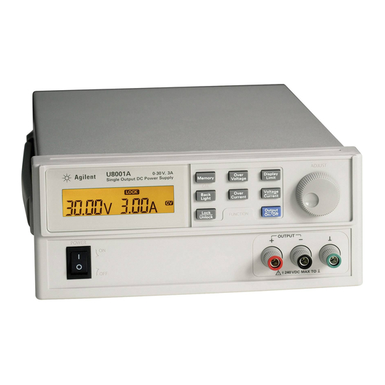
- Page 1 Agilent U8001A/U8002A Single Output DC Power Supplies User’s and Service Guide Agilent Technologies...
-
Page 2: Safety Notices
Agilent Technologies, Inc. information contained herein. Should 3501 Stevens Creek Blvd. Agilent and the user have a separate Santa Clara, CA 95052 USA written agreement with warranty terms covering the material in this WA R N I N G ®... -
Page 3: Safety Symbols
Caution, risk of danger (refer to this manual for specific Warning or Caution information. Protective conductor terminal Caution, hot surface. Frame or chassis terminal Out position of a bi-stable push control. Equipotentiality In position of a bi-stable push control. U8001A/U8002A User’s and Service Guide... - Page 4 Agilent Technologies assumes no liability for customer’s failure to comply with these requirements. • Do not use the device if it appears damaged or defective.
-
Page 5: Environment Conditions
Storage Temperature –20 °C to 70 °C Altitude Up to 2000 m The Agilent U8001A/U8002A single output DC power supplies comply C A U T I O N with the following safety and EMC requirements: • IEC 61326:2002 / EN 61326:1997+A1:1998+A3:2003 •... - Page 6 Radio Communication Act of 1992. This instrument complies with the WEEE Directive (2002/96/EC) marking requirement. This affixed product label indicates that you must not discard this electrical/electronic product in domestic household waste. U8001A/U8002A User’s and Service Guide...
- Page 7 “Monitoring and Control Instrument” product. The affixed product label is shown as below: Do not dispose in domestic household waste To return this unwanted instrument, contact your nearest Agilent office, or visit: www.agilent.com/environment/product for more information.
- Page 8 26-May-2008 Tay Eng Su Date Quality Manager For further information, please contact your local Agilent Technologies sales office, agent or distributor, or Agilent Technologies Deutschland GmbH, Herrenberger Straße 130, 71034 Böblingen, Germany. Template: A5971-5302-2, Rev. E U8001A DoC Revision 1.0 VIII U8001A/U8002A User’s and Service Guide...
- Page 9 Regulatory Information for Canada ICES/NMB-001:2004 This ISM device complies with Canadian ICES-001. Cet appareil ISM est confomre à la norme NMB-001 du Canada. Regulatory Information for Australia/New Zealand This ISM device complies with Australian/New Zealand AS/NZS CISPR11:2004 U8001A/U8002A User’s and Service Guide...
- Page 10 This guide provides step- by- step set up and configuration instructions that get you familiarized with the operations of the Agilent U8001A/U8002A single output DC power supplies. This guide also contains service information and troubleshooting guidelines that help to resolve your problems during startup configurations.
-
Page 11: Table Of Contents
Front Panel at a Glance Rear Panel at a Glance Display Annunciators Description Installation Initial inspection Cooling and location Output Connections Voltage drops Chapter 3 Operations and Features Constant Voltage Operation Constant Current Operation Memory Operations Storing Operating State U8001A/U8002A User’s and Service Guide... - Page 12 Performance Specifications Supplemental Characteristics Chapter 5 Service Guide Equipment Warranty Replacement Parts Troubleshooting Line Voltage Conversion Performance Verification and Calibration Constant Current (CC) Verification Voltage Calibration Current Calibration Appendix Appendix A: List of Error Codes U8001A/U8002A User’s and Service Guide...
-
Page 13: Agilent Technologies
Agilent U8001A/U8002A Sinlge Output DC Power Supplies User’s and Service Guide Quick Start Preliminary Checkout Output Checkout If the Power Supply Does Not Turn On To Rack-mount the Instrument This chapter is intended for both the experienced and inexperienced users because it calls attention to certain checks that should be made prior to operation. -
Page 14: Chapter 1 Quick Start
1 Check the list of supplied item. Verify that you have received the following items together with your power supply. If anything is found missing, contact your nearest Agilent Technologies Sales Office. • Power cord • Certificate of Calibration •... -
Page 15: Output Checkout
5 Ensure that the voltage can be adjusted from zero to the full rated value by adjusting the knob. When the power supply is turned on, the last memory will be shown on the N O T E display. U8001A/U8002A User’s and Service Guide... -
Page 16: Current Output Checkout
6 Ensure that the current can be adjusted from zero to the full rated value. 7 Turn off the power supply and remove the short from the output terminals. U8001A/U8002A User’s and Service Guide... -
Page 17: If The Power Supply Does Not Turn On
Chapter 5 for instructions on returning the instrument to Agilent Technologies for service. 1 Verify that there is ac power to the power supply. First, verify that the power cord is firmly plugged into the power receptacle on the rear panel of the power supply. You should also make sure that the power source you plugged the power supply into is energized. -
Page 18: To Rack-Mount The Instrument
5061- 9694 and flange kit, 5063- 9212. Be sure to use the support rails inside the rack cabinet. To install two instruments in a sliding support shelf, order support shelf, 5063- 9255, and slide kit, 1494- 0015. U8001A/U8002A User’s and Service Guide... - Page 19 Agilent U8001A/U8002A Single Output DC Power Supplies User’s and Service Guide General Information Front Panel at a Glance Rear Panel at a Glance Display Annunciators Description Installation Output Connections This chapter provides general description of the instrument, front panel overview, rear panel overview, display annunciators and installation guidelines for U8001A/U8002A single output DC power supplies.
-
Page 20: Chapter 2 General Information
Enables and disables the power supply output. Knob Increases and decreases the value of the flashing digit. Power On/Off To turn On/Off the power supply. Binding posts Positive, negative and ground binding posts for wire connections. U8001A/U8002A User’s and Service Guide... -
Page 21: Rear Panel At A Glance
Sets the line voltage to the proper values for different country based. assembly Power-line module Combination of the AC inlet and power fuse-holder assembly. Physical lock mechanism Enables physical lock mechanism. Line Voltage Fuse Rating Indicates the line voltage and line fuse rating. indicator U8001A/U8002A User’s and Service Guide... -
Page 22: Display Annunciators
The display shows the limit values of voltage and current. The output of the power supply is disabled. The power supply is in constant voltage mode when the annunciator blinks. The power supply is in constant current mode when the annuciator blinks U8001A/U8002A User’s and Service Guide... -
Page 23: Description
General Information Description The Agilent U8001A/U8002A single output DC power supplies are compact, general purpose bench supplies that are suitable for either bench or rack- mounted operations. These power supplies feature linear power supply performance and capable usabilities, making them ideal for power systems applications. - Page 24 Front panel binding posts are available to connect load wires for bench operation. Floating the power supply output more than ±240 Vdc from the WA R N I N G chassis presents an electric shock hazard to the operator. U8001A/U8002A User’s and Service Guide...
-
Page 25: Installation
Keep the original packing materials in case the power supply has to be returned to Agilent Technologies in the future. If you return the power supply for service, attach a tag identifying the owner and model number. Also include a brief description of the problem. -
Page 26: Cooling And Location
40 °C to 55 °C. A fan cools the power supply by drawing air through the sides and exhausting it out the back. Using an Agilent rack- mount will not impede the flow of air. Bench Operation Your power supply must be installed in a location that allows sufficient space at the sides and rear of the power supply for adequate air circulation. -
Page 27: Output Connections
The voltage drops across the load wires should be limited to less than 2 V. Refer to the American Wire Gauge (AWG) standard to calculate the voltage drop for some commonly used AWG wire copper. U8001A/U8002A User’s and Service Guide... - Page 28 General Information U8001A/U8002A User’s and Service Guide...
- Page 29 You have now learned how to install the power supply. You were also briefly introduced to the front panel keys and their functionality from previous chapter. This chapter shows you the operations and features for the U8001A/U8002A single output DC power supplies. Agilent Technologies...
-
Page 30: Chapter 3 Operations And Features
4 Adjust for the desired current limit. • Press on the “Voltage/Current” button. When seeing the current value, “A” blinks, turn the knob to adjust for the desired current limit value. U8001A/U8002A User’s and Service Guide... - Page 31 Verify that the power supply is in constant voltage mode. Ensure that the N O T E constant voltage (CV) annunciator is on. If the constant current (CC) annunciator is on instead, choose a higher current limit. U8001A/U8002A User’s and Service Guide...
-
Page 32: Constant Current Operation
4 Adjust for the desired voltage limit. • Press on the “Voltage/Current” button. When seeing the voltage value, “V” blinks, turn the knob to adjust for the desired voltage limit value. U8001A/U8002A User’s and Service Guide... - Page 33 Verify that the power supply is in constant current mode. Ensure that the N O T E constant current (CC) annunciator is on. If the constant voltage (CV) annunciator is on instead, choose a higher voltage limit. U8001A/U8002A User’s and Service Guide...
-
Page 34: Memory Operations
Operations and Features Memory Operations For Agilent U8001A/U8002A single output DC power supplies, up to three operating states can be stored in non- volatile storage locations. The storage feature remembers the voltage † and current limit value settings, OVP /OCP On/Off states, and OVP/OCP trip levels. -
Page 35: Recalling Operating State
3 Press on the “Memory” button if you want to use the shown settings as the current operating settings • The M1, M2 and M3 annunciators will be turned off. To cancel the operation, allow the unit to idle for five seconds. N O T E U8001A/U8002A User’s and Service Guide... -
Page 36: Programming Over Voltage Protection
3 Press on the “Over Voltage” button again to end the adjustment and enable the OVP. • Display will show “donE”. • The OVP annunciator will be turned on. To cancel the operation, allow the unit to idle for five seconds. N O T E U8001A/U8002A User’s and Service Guide... - Page 37 • The display will show “TRIP”. 2 To clear the OVP trip conditon, press on the “Over Voltage” button again. If OVP trip persists, decrease the voltage limit settings to clear the N O T E tripping. U8001A/U8002A User’s and Service Guide...
-
Page 38: Programming Over Current Protection
3 Press on the “Over Current” button again to end the adjustment and enable the OCP. • Display will show “donE”. • The OCP annunciator will be turned on. To cancel the operation, allow the unit to idle for five seconds. N O T E U8001A/U8002A User’s and Service Guide... - Page 39 • The display will show “TRIP”. 2 To clear the OCP trip conditon, press on the “Over Current” button again. If OCP trip persists, decrease the current limit settings to clear the tripping. N O T E U8001A/U8002A User’s and Service Guide...
-
Page 40: Keylock Operation
1 Press and hold down the “Lock/Unlock” button for three seconds. 2 When the “Lock/Unlock” button is being held down, the display will show “HOLD” until the keylock is disabled. 3 After the keylock is disabled, the LOCK annunciator will be turned off . U8001A/U8002A User’s and Service Guide... -
Page 41: Backlight Operation
To turn on the backlight 1 Press on the “Back Light” button. The backlight will be turned on. To turn off the backlight 1 Press on the “Back Light” button. The backlight will be turned off. U8001A/U8002A User’s and Service Guide... -
Page 42: System Related Operations
If the test fails, the display will show “Err” with the error code. See N O T E “Appendix A: List of Error Codes” for more information. U8001A/U8002A User’s and Service Guide... -
Page 43: Chapter 4 Specifications And Characteristics
Agilent U8001A/U8002A Single Output DC Power Supplies User’s and Service Guide Specifications and Characteristics Performance Specifications Supplemental Characteristics This chapter lists the power supply’s performance specifications and the supplemental characteristics of the equipment. Agilent Technologies... -
Page 44: Performance Specifications
Readback Accuracy (25 °C ±5 ° C) <0.35% +20 mV <0.35% +20 mA Meter Resolution Voltage: 10 mV Current: 10 mA Maximum Output Float Voltage ±240 Vdc * Specifications are based on 1-hour warm-up period. U8001A/U8002A User’s and Service Guide... -
Page 45: Supplemental Characteristics
Over Voltage Protection Programmable 1 V to 33 V Range Over Current Protection Accuracy <0.5% +0.5 A ± (% of output + offset) Over Current Protection Programmable 1 A to 3.3 A 1 A to 5.5 A Range U8001A/U8002A User’s and Service Guide... - Page 46 , 47 to 63 Hz Fuse External, customer assessable Table 4-5 Physical Specifications Parameter U8001A U8002A Dimension (W x H x L) 88.1 mm x 212.3 mm x 394.3 mm Weight (kg) 7.3 kg 8.3 kg U8001A/U8002A User’s and Service Guide...
-
Page 47: Chapter 5 Service Guide
Agilent U8001A/U8002A Single Output DC Power Supplies User’s and Service Guide Service Guide Equipment Warranty Replacement Parts Troubleshooting Performance Verification and Calibration Voltage Calibration Current Calibration This chapter contains service information for the U8001A/U8002A single output DC power supplies, including... -
Page 48: Equipment Warranty
To obtain warranty, service, or technical support information you can contact Agilent Technologies at one of the following telephone numbers: In the United States: (800) 829- 4444... -
Page 49: Repackaging For Shipment
Agilent recommends that you retain the original shipping carton for use in such shipments. Repackaging for Shipment If the unit is to be shipped to Agilent for service or repair, be sure to: • Attach a tag to the unit identifying the owner and indicating the required service or repair. -
Page 50: Replacement Parts
To order replaceable parts from Agilent, do the following: 1 Contact your nearest Agilent Sales Office or Service Center. 2 Identify the parts by the Agilent part number shown in the replaceable parts list. 3 Provide the instrument model number and serial number. -
Page 51: Troubleshooting
Fuse 4.0 A T for 100 Vac and 115 Vac 2110-0006 Fuse 2.0 A T for 230 Vac U8002A 2110-0722 Fuse 6.25 A T for 100 Vac and 115 Vac 2110-1425 Fuse 2.8 A T for 230 Vac U8001A/U8002A User’s and Service Guide... -
Page 52: Line Voltage Conversion
3 Remove the voltage selector 4 Replace the correct fuse and orientate the PCB based on the PCB using a flat- blade correct voltage. screwdriver. U8001A/U8002A User’s and Service Guide... - Page 53 100 indication needs to be in this orientation 115 indication needs to be in this orientation 230 V 230 indication needs to be in this orientation Figure 5-1 Orientation of voltage selector AC inlet in different voltage selection U8001A/U8002A User’s and Service Guide...
- Page 54 Verify that the correct power- line voltage setting is selected. Also, ensure that all terminal connections are removed while the self- test is performed. Please refer to “Appendix A: List of Error Codes” for list of error codes. U8001A/U8002A User’s and Service Guide...
-
Page 55: Performance Verification And Calibration
This will increase your confidence that the U8001A and U8002A will remain within specification for the next calibration interval. The re- adjustment provides the best long- term stability and accuracy. -
Page 56: Recommended Test Equipment
• Current range: 5 A line regulations and • Open and Short switches transient response • Transient On/Off time AC Power Source Capable of supplying Agilent 6813B Functions as variable voltage transformer 90 Vac to 250 Vac U8001A/U8002A User’s and Service Guide... - Page 57 Service Guide Table 5-2 List of Equipment Equipment Requirement(s) Recommended Model Purpose Used • 10 Ω/90 W (for U8001A) Resistive Load (R Measures ripple and • 6 Ω/150 W (for U8002A) noise • 0.01 Ω ± 0.1% Current Monitoring ISOTEK Co.
-
Page 58: Measurement Techniques
Measurement Techniques Test Setup Most tests are performed at the front terminals as shown below. Measure the DC voltage directly at the positive (+) and negative (–) terminals on the front panel. Figure 5-2 Test Setups U8001A/U8002A User’s and Service Guide... - Page 59 To avoid mutual coupling effects, each measuring device must be connected directly to the output terminals by separate pairs of leads. Figure 5-3 General Measurement U8001A/U8002A User’s and Service Guide...
- Page 60 Substitution of the electronic load requires minor changes to the test procedures in this chapter. U8001A/U8002A User’s and Service Guide...
- Page 61 30 V ± 0.125 V. 13 When the power supply is in meter mode, record the voltage reading displayed on the front display of the power supply. This value should be within the limit of V ± 0.125 V. U8001A/U8002A User’s and Service Guide...
- Page 62 4 Enable the output. 5 Operate the electronic load in constant current mode and set its current to 3 A for U8001A and 5 A for U8002A. Ensure that the power supply is in CV mode. If not, adjust the electronic load so that the current drops slightly until the power supply is in CV mode.
- Page 63 5 Enable the output. 6 Operate the electronic load in constant current mode and set its current to 3 A for U8001A and 5 A for U8002A. Ensure that the power supply is in CV mode. If not, adjust the electronic load so that the output current drops slightly until the power supply is in CV mode.
- Page 64 • Acquires every single sample at the maximum sampling rate and retains only the min and max values in a "sampling region" (50 ms time range) • Enable 20 MHz cut off frequency for better high frequency cut- off • AC coupling U8001A/U8002A User’s and Service Guide...
- Page 65 11 Disconnect the oscilloscope and connect an RMS voltmeter in Ω its place. Do not disconnect the 50 termination. Divide the reading of the RMS voltmeter by 10. The result should not exceed the RMS limits of 1 mV U8001A/U8002A User’s and Service Guide...
- Page 66 7 Adjust the oscilloscope to display transients as shown in Figure 5- 4. Note that the pulse width (t2–t1) of the transients at 15 mV from the base line is no more than 50 µs for the output. U8001A/U8002A User’s and Service Guide...
- Page 67 Service Guide Figure 5-4 Graph of load transient response U8001A/U8002A User’s and Service Guide...
-
Page 68: Constant Current (Cc) Verification
±10 mA. 8 Disable the output. 9 When the power supply is in limit mode, program the output current to full rated value, i.e. 3 A for U8001A and 5 A for U8002A. 10 Enable the output. 11 Wait for a few seconds for the output of the power supply to settle. - Page 69 (I ). This value should be within the limit of: • U8001A: 3 A ±30.5 mA • U8002A: 5 A ±37.5 mA 13 When the power supply is in meter mode, record the current reading displayed on the front display of the power supply.
- Page 70 3 When the power supply is in limit mode, program the output voltage to maximum programmable value and output current to full rated value, i.e. 3 A for U8001A and 5A for U8002A. 4 Enable the output. 5 Operate the electronic load in constant voltage mode and set its voltage to 30 V.
- Page 71 4 When the display is in the limit mode, program the output voltage to maximum programmable value and output current to full rated value, i.e. 3 A for U8001A and 5 A for U8002A. 5 Enable the output. 6 Operate the electronic load in constant voltage mode and set its voltage to 30 V.
- Page 72 9 Compare the reading obtained in steps 7 and 8. The difference should be within the limit of: • U8001A: 2.6 mA • U8002A: 3 mA Line Voltage Low Line Voltage Limit, V High Line Voltage Limit, V U8001A/U8002A User’s and Service Guide...
- Page 73 3 When the display is in the limit mode, program the output voltage to maximum programmable value and output current to full rated value, i.e. 3 A for U8001A and 5 A for U8002A. 4 Enable the output. 5 Make sure that the power supply is in CC mode. If not, adjust the resistive load so that the output voltage drops slightly until the power supply is in CC mode.
-
Page 74: Voltage Calibration
• Use the knob to enter the reading obtained from the DVM. • Press the "Memory" button to save the changes and move to the next calibration point. You will be able to perform this if the power supply is in CV mode. U8001A/U8002A User’s and Service Guide... - Page 75 If you do not wish to continue with the current calibration, you may now N O T E turn off the power supply to exit the calibration mode. U8001A/U8002A User’s and Service Guide...
-
Page 76: Current Calibration
• Press the "Memory" button to save the changes and move to the next calibration point. You will be able to perform this if the power supply is in CC mode. U8001A/U8002A User’s and Service Guide... - Page 77 • Turn off the power supply to exit the calibration mode. 8 Toggle between calibration modes • Along the calibration process, you can toggle between voltage calibration mode and current calibration mode by pressing the "Voltage/Current" button. U8001A/U8002A User’s and Service Guide...
- Page 78 Service Guide U8001A/U8002A User’s and Service Guide...
-
Page 79: Appendix
Agilent U8001A/U8002A Single Output DC Power Supplies User’s and Service Guide Appendix Appendix A: List of Error Codes Agilent Technologies... -
Page 80: Appendix A: List Of Error Codes
Descriptions Flash read/write failed Calibration failed for DAC CV Calibration failed for DAC CC Calibration failed for ADC CV Calibration failed for ADC CC Calibration failed for DAC OV Calibration failed for DAC OC Agilent U8001A/U8002A User’s and Service Guide... - Page 81 (fax) (65) 6755 0042 Or visit Agilent worldwide web at: www.agilent.com/find/assist Product specifications and descriptions in this document subject to change without notice. Always refer to Agilent web site for the latest revision. © Agilent Technologies, Inc. 2008 Printed in Malaysia...