ASROCK Fatal1ty Z97 Killer Series Manual
Hide thumbs
Also See for Fatal1ty Z97 Killer Series:
- User manual (144 pages) ,
- User manual (124 pages) ,
- Manual (186 pages)
Table of Contents
Advertisement
Available languages
Available languages
Version 1.1
Published May 2014
Copyright©2014 ASRock INC. All rights reserved.
Copyright Notice:
No part of this documentation may be reproduced, transcribed, transmitted, or
translated in any language, in any form or by any means, except duplication of
documentation by the purchaser for backup purpose, without written consent of
ASRock Inc.
Products and corporate names appearing in this documentation may or may not
be registered trademarks or copyrights of their respective companies, and are used
only for identiication or explanation and to the owners' beneit, without intent to
infringe.
Disclaimer:
Speciications and information contained in this documentation are furnished for
informational use only and subject to change without notice, and should not be
constructed as a commitment by ASRock. ASRock assumes no responsibility for
any errors or omissions that may appear in this documentation.
With respect to the contents of this documentation, ASRock does not provide
warranty of any kind, either expressed or implied, including but not limited to
the implied warranties or conditions of merchantability or itness for a particular
purpose.
In no event shall ASRock, its directors, oicers, employees, or agents be liable for
any indirect, special, incidental, or consequential damages (including damages for
loss of proits, loss of business, loss of data, interruption of business and the like),
even if ASRock has been advised of the possibility of such damages arising from any
defect or error in the documentation or product.
his device complies with Part 15 of the FCC Rules. Operation is subject to the following
two conditions:
(1) this device may not cause harmful interference, and
(2) this device must accept any interference received, including interference that
may cause undesired operation.
CALIFORNIA, USA ONLY
he Lithium battery adopted on this motherboard contains Perchlorate, a toxic substance
controlled in Perchlorate Best Management Practices (BMP) regulations passed by the
California Legislature. When you discard the Lithium battery in California, USA, please
follow the related regulations in advance.
"Perchlorate Material-special handling may apply, see www.dtsc.ca.gov/hazardouswaste/
perchlorate"
ASRock Website: http://www.asrock.com
Advertisement
Table of Contents

Related Manuals for ASROCK Fatal1ty Z97 Killer Series


Summary of Contents for ASROCK Fatal1ty Z97 Killer Series
-
Page 1: Copyright Notice
(including damages for loss of proits, loss of business, loss of data, interruption of business and the like), even if ASRock has been advised of the possibility of such damages arising from any defect or error in the documentation or product. - Page 2 he terms HDMI™ and HDMI High-Deinition Multimedia Interface, and the HDMI logo are trademarks or registered trademarks of HDMI Licensing LLC in the United States and other countries. Manufactured under license under U.S. Patent Nos: 5,956,674; 5,974,380; 6,487,535; 7,003,467 & other U.S. and worldwide patents issued & pending. DTS, the Symbol, & DTS and the Symbol together is a registered trademark &...
- Page 3 Fatal1ty Story Who knew that at age 19, I would be a World Champion PC gamer. When I was 13, I actually played competitive billiards in professional tournaments and won four or ive games of guys who played at the highest level. I actually thought of making a career of it, but at that young age situations change rapidly.
- Page 4 LIVIN’ LARGE Since my irst big tournament wins, I have been a “Professional Cyberathlete”, traveling the world and livin’ large with lots of International media coverage on outlets such as MTV, ESPN and a 60 Minutes segment on CBS to name only a few. It's unreal - it's crazy. I’m living a dream by playing video games for a living.
-
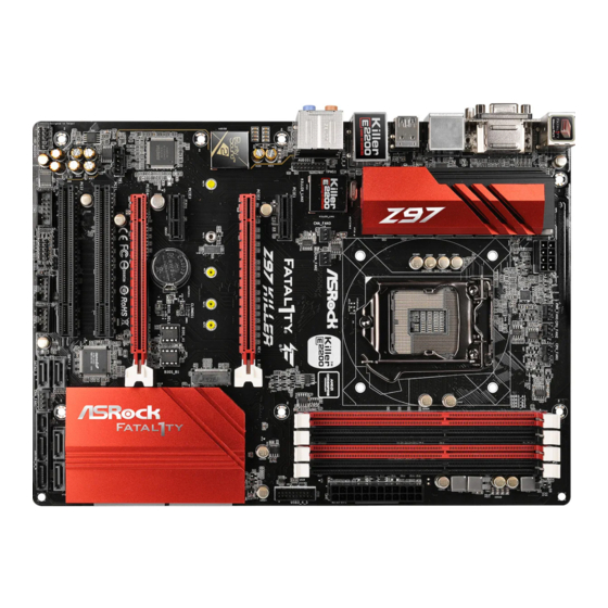
Page 5: Motherboard Layout
Fatal1ty Z97 Killer Series Motherboard Layout PWR_FAN1 CPU_FAN2 CPU_FAN1 ATX12V1 USB 3.0 Top: T: USB2 RJ-45 B: USB3 CHA_FAN2 Killer CHA_FAN3 E2200 GAME NETWORKING FATAL TPMS1 PCIE1 Z97 KILLER PCIE2 Purity Sound 2 NUT6 NUT5 NUT4 NUT3 NUT2 Intel CLRMOS1... - Page 6 No. Description ATX 12V Power Connector (ATX12V1) Power Fan Connector (PWR_FAN1) CPU Fan Connector (CPU_FAN2) CPU Fan Connector (CPU_FAN1) 2 x 240-pin DDR3 DIMM Slots (DDR3_A1, DDR3_B1) 2 x 240-pin DDR3 DIMM Slots (DDR3_A2, DDR3_B2) ATX Power Connector (ATXPWR1) USB 3.0 Header (USB3_4_5) SATA3 Connector (SATA3_1) SATA3 Connector (SATA3_2) SATA3 and SATA Express Connectors (SATAE_5_4)
- Page 7 Fatal1ty Z97 Killer Series I/O Panel No. Description No. Description USB 2.0 Ports (USB01) Front Speaker (Lime)** D-Sub Port Microphone (Pink) Fatal1ty Mouse Port (USB2) Optical SPDIF Out Port USB 2.0 Port (USB3) USB 3.0 Ports (USB3_2_3) LAN RJ-45 Port* USB 3.0 Ports (USB3_0_1)
- Page 8 * here are two LEDs on each LAN port. Please refer to the table below for the LAN port LED indications. ACT/LINK LED SPEED LED LAN Port Activity / Link LED Speed LED Status Description Status Description No Link 10Mbps connection Blinking Data Activity Orange...
-
Page 9: Chapter 1 Introduction
If you require technical support related to this motherboard, please visit our website for speciic information about the model you are using. You may ind the latest VGA cards and CPU support list on ASRock’s website as well. ASRock website http://www.asrock.com. - Page 10 Processors (Socket 1150) • Digi Power design • 8 Power Phase design • Supports Intel® Turbo Boost 2.0 Technology • Supports Intel® K-Series unlocked CPUs • Supports ASRock BCLK Full-range Overclocking • Intel® Z97 Chipset • Dual Channel DDR3 Memory Technology Memory • 4 x DDR3 DIMM Slots...
- Page 11 • 7.1 CH HD Audio with Content Protection (Realtek ALC1150 Audio Audio Codec) • Premium Blu-ray Audio support • Supports Surge Protection (ASRock Full Spike Protection) • Supports Purity Sound - Nichicon Fine Gold Series Audio Caps - 115dB SNR DAC with Diferential Ampliier - TI®...
- Page 12 • 1 x DVI-D Port • 1 x HDMI Port • 1 x Optical SPDIF Out Port • 3 x USB 2.0 Ports (Supports ESD Protection (ASRock Full Spike Protection)) • 1 x Fatal1ty Mouse Port (USB 2.0) (Supports ESD Protection (ASRock Full Spike Protection)) • 4 x USB 3.0 Ports (Supports ESD Protection (ASRock Full...
- Page 13 Due to limitation, the actual memory size may be less than 4GB for the reservation for system usage under Windows® 32-bit operating systems. Windows® 64-bit operat- ing systems do not have such limitations. You can use ASRock XFast RAM to utilize the memory that Windows® cannot use.
-
Page 14: Chapter 2 Installation
Chapter 2 Installation his is an ATX form factor motherboard. Before you install the motherboard, study the coniguration of your chassis to ensure that the motherboard its into it. Pre-installation Precautions Take note of the following precautions before you install motherboard components or change any motherboard settings. -
Page 15: Installing The Cpu
Fatal1ty Z97 Killer Series 2.1 Installing the CPU 1. Before you insert the 1150-Pin CPU into the socket, please check if the PnP cap is on the socket, if the CPU surface is unclean, or if there are any bent pins in the socket. - Page 16 English...
- Page 17 Fatal1ty Z97 Killer Series Please save and replace the cover if the processor is removed. he cover must be placed if you wish to return the motherboard for ater service.
- Page 18 2.2 Installing the CPU Fan and Heatsink...
-
Page 19: Dual Channel Memory Coniguration
Fatal1ty Z97 Killer Series 2.3 Installing Memory Modules (DIMM) his motherboard provides four 240-pin DDR3 (Double Data Rate 3) DIMM slots, and supports Dual Channel Memory Technology. 1. For dual channel coniguration, you always need to install identical (the same brand, speed, size and chip-type) DDR3 DIMM pairs. - Page 20 English...
-
Page 21: Expansion Slots
Fatal1ty Z97 Killer Series 2.4 Expansion Slots (PCI and PCI Express Slots) here are 2 PCI slots and 4 PCI Express slots on the motherboard. Before installing an expansion card, please make sure that the power supply is switched of or the power cord is unplugged. Please read the documentation of the expansion card and make necessary hardware settings for the card before you start the installation. -
Page 22: Jumpers Setup
2.5 Jumpers Setup he illustration shows how jumpers are setup. When the jumper cap is placed on the pins, the jumper is “Short”. If no jumper cap is placed on the pins, the jumper is “Open”. he illustration shows a 3-pin jumper whose pin1 and pin2 are “Short” when a jumper cap is placed on these 2 pins. - Page 23 Fatal1ty Z97 Killer Series BIOS Selection Jumper (BIOS_SEL1) Default Backup BIOS (see p.1, No. 23) (Main BIOS) his motherboard has two BIOS onboard, a main BIOS (BIOS_A) and a backup BIOS (BIOS_B), which enhances protection for the safety and stability of your system.
-
Page 24: Onboard Headers And Connectors
2.6 Onboard Headers and Connectors Onboard headers and connectors are NOT jumpers. Do NOT place jumper caps over these headers and connectors. Placing jumper caps over the headers and connectors will cause permanent damage to the motherboard. System Panel Header Connect the power PLED+ PLED-... - Page 25 Fatal1ty Z97 Killer Series Power LED Header Please connect the chassis (3-pin PLED1) power LED to this header PLED- PLED+ PLED+ (see p.1, No. 17) to indicate the system’s power status. Serial ATA3 Connectors hese six SATA3 (SATA3_0: connectors support SATA see p.1, No.
- Page 26 USB 3.0 Headers Besides four USB 3.0 Vbus Vbus Vbus IntA_PB_SSRX- (19-pin USB3_4_5) ports on the I/O panel, IntA_PB_SSRX+ IntA_PA_SSRX- IntA_PA_SSRX+ (see p.1, No. 8) there is one header on this IntA_PB_SSTX- IntA_PA_SSTX- IntA_PB_SSTX+ motherboard. Each USB IntA_PA_SSTX+ IntA_PB_D- 3.0 header can support IntA_PA_D- IntA_PB_D+ IntA_PA_D+...
- Page 27 Fatal1ty Z97 Killer Series (3-pin PWR_FAN1) FAN_SPEED +12V (see p.1, No. 2) CPU Fan Connectors his motherboard pro- FAN_SPEED_CONTROL FAN_SPEED (4-pin CPU_FAN1) vides a 4-Pin CPU fan +12V (see p.1, No. 4) (Quiet Fan) connector. If you plan to connect a...
- Page 28 TPM Header his connector supports (17-pin TPMS1) Trusted Platform Module (see p.1, No. 25) (TPM) system, which can securely store keys, digital certiicates, passwords, PCIRST# FRAME and data. A TPM system PCICLK also helps enhance network security, protects digital identities, and ensures platform integrity.
- Page 29 Fatal1ty Z97 Killer Series 2.7 M.2_SSD (NGFF) Module Installation Guide The M.2, also known as the Next Generation Form Factor (NGFF), is a small size and versatile card edge connector that aims to replace mPCIe and mSATA. The M.2_SSD (NGFF) Socket 3 can accommodate either a M.2 SATA3 6.0 Gb/s module or a M.2 PCI Express module up to Gen 2 x2 (10 Gb/s).
- Page 30 Step 3 Move the standof based on the module type and length. he standof is placed at the nut location D by default. Skip Step 3 and 4 and go straight to Step 5 if you are going to use the default nut. Otherwise, release the standof by hand.
- Page 31 Fatal1ty Z97 Killer Series Step 6 Tighten the screw with a screwdriver to secure the module into place. Please do not overtighten the screw NUT2 NUT1 as this might damage the module. M.2_SSD (NGFF) Module Support List PCIe Interface SATA Interface...
- Page 32 1 Einleitung Vielen Dank für den Kauf unseres ASRock Fatal1ty Z97 Killer Series, eines zuverlässigen Motherboards, das nach ASRocks strengen Qualitätsrichtlinien gefertigt wurde. Es liefert ausgezeichnete Leistung mit robustem Design, das ASRocks Streben nach Qualität und Beständigkeit erfüllt. Da die technischen Daten des Motherboards sowie die BIOS-Sotware aktualisiert werden können, kann der Inhalt dieser Anleitung ohne Ankündigung geändert werden.
-
Page 33: Technische Daten
Prozessoren (Sockel 1150) der 5., 4. und neuen 4. Generation • Digipower-Design • 8-Leistungsphasendesign • Unterstützt Intel® Turbo Boost 2.0-Technologie • Unterstützt CPUs mit freiem Multiplikator der Intel® K-Serie • Unterstützt ASRock BCLK-Übertaktung (voller Bereich) • Intel® Z97 Chipsatz • Dualkanal-DDR3-Speichertechnologie Speicher • 4 x DDR3-DIMM-Steckplätze... - Page 34 DVI-D- und HDMI-Ports • 7.1-Kanal-HD-Audio mit Inhaltsschutz (Realtek ALC1150- Audio Audiocodec) • Erstklassige Blu-ray-Audiounterstützung • Unterstützt Überspannungsschutz (ASRock Full Spike Protection) • Unterstützt Purity Sound - Nichicon-Audiokappen der Fine Gold-Serie - 115-dB-SRV-DAC mit Diferentialverstärker - TI® NE5532 – erstklassiger Headset-Verstärker (unterstützt...
- Page 35 • 1 x Audioanschluss an Frontblende • 1 x hunderbolt-Erweiterungskartenanschluss • 2 x USB 2.0-Stitleisten (unterstützen 4 USB 2.0-Ports) (unterstützt Schutz gegen elektrostatische Entladung (ASRock Full Spike Protection)) • 1 x USB 3.0-Stitleiste (unterstützt 2 USB 3.0-Ports) (unterstützt Schutz gegen elektrostatische Entladung (ASRock Full Spike Protection)) • 2 x 64-Mb-AMI-UEFI-Legal-BIOS mit Unterstützung mehr-...
- Page 36 Aufgrund von Beschränkungen kann die Größe des tatsächlich für die Systemnutzung reservierten Speichers unter Windows®-Betriebssystemen mit 32 Bit weniger als 4 GB betragen. Windows®-Betriebssysteme mit 64 Bit haben keine derartigen Beschränkungen. Mit ASRock XFast RAM können Sie den Speicher einsetzen, den Windows® nicht nutzen kann.
- Page 37 Fatal1ty Z97 Killer Series 1.3 Jumpereinstellung Die Abbildung zeigt, wie die Jumper eingestellt werden. Wenn die Jumper-Kappe auf den Kontakten angebracht ist, ist der Jumper „kurzgeschlossen“. Wenn keine Jumper- Kappe auf den Kontakten angebracht ist, ist der Jumper „ofen“. Die Abbildung zeigt einen 3-poligen Jumper, dessen Kontakt 1 und Kontakt 2 „kurzgeschlossen“...
- Page 38 BIOS-Auswahl-Jumper (BIOS_SEL1) Standard Ausfall-BIOS (siehe S. 1, Nr. 23) (Haupt-BIOS) Dieses Motherboard verfügt über zwei integrierte BIOS, ein Haupt-BIOS (BIOS_A) und ein Ausfall-BIOS (BIOS_B), die den Schutz in puncto Sicherheit und Stabilität Ihres Systems steigern. Normalerweise läut das System über das Haupt-BIOS.
-
Page 39: Integrierte Stiftleisten Und Anschlüsse
Fatal1ty Z97 Killer Series 1.4 Integrierte Stiftleisten und Anschlüsse Integrierte Stitleisten und Anschlüsse sind KEINE Jumper. Bringen Sie KEINE Jumper- Kappen an diesen Stitleisten und Anschlüssen an. Durch Anbringen von Jumper-Kappen an diesen Stitleisten und Anschlüssen können Sie das Motherboard dauerhat beschädi- gen. - Page 40 Betrieb-LED-Stitleiste Bitte verbinden Sie die (3-polig, PLED1) Betrieb-LED des Gehäuses PLED- PLED+ (siehe S. 1, Nr. 17) zur Anzeige des System- PLED+ betriebsstatus mit dieser Stitleiste. Serial-ATA-III-Anschlüsse Diese sechs SATA-III- (SATA3_0: Anschlüsse unterstützen siehe S. 1, Nr. 14) SATA-Datenkabel für SATA3_0 SATA3_1 SATA3_2...
- Page 41 Fatal1ty Z97 Killer Series USB 3.0-Stitleisten Neben vier USB 3.0-Ports Vbus Vbus Vbus IntA_PB_SSRX- (19-polig, USB3_4_5) an der E/A-Blende beindet IntA_PB_SSRX+ IntA_PA_SSRX- (siehe S. 1, Nr. 8) sich eine Stitleiste an IntA_PA_SSRX+ IntA_PB_SSTX- diesem Motherboard. Jede IntA_PA_SSTX- IntA_PB_SSTX+ IntA_PA_SSTX+ USB 3.0-Stitleiste kann IntA_PB_D- zwei Ports unterstützen.
- Page 42 (3-polig, PWR_FAN1) FAN_SPEED +12V (siehe S. 1, Nr. 2) CPU-Lüteranschlüsse Dieses Motherboard bietet FAN_SPEED_CONTROL FAN_SPEED (4-polig, CPU_FAN1) einen 4-poligen CPU- +12V (siehe S. 1, Nr. 4) Lüteranschluss (lautloser Lüter). Falls Sie einen (3-polig, CPU_FAN2) 3-poligen CPU-Lüter (siehe S. 1, Nr. 3) anschließen möchten, FAN_SPEED verbinden Sie ihn bitte mit...
- Page 43 Fatal1ty Z97 Killer Series TPM-Stitleiste Dieser Anschluss (17-polig, TPMS1) unterstützt das Trusted (siehe S. 1, Nr. 25) Platform Module- (TPM) System, das Schlüssel, digitale Zertiikate, PCIRST# FRAME Kennwörter und Daten PCICLK sicher aubewahren kann. Ein TPM-System hilt zudem bei der Stärkung der Netzwerksicherheit, schützt digitale Identitäten...
- Page 44 à modiication sans préavis. En cas de modiications du présent document, la version mise à jour sera disponible sur le site Internet ASRock sans notiica- tion préalable. Si vous avez besoin d’une assistance technique pour votre carte mère, veuillez visiter notre site Internet pour plus de détails sur le modèle que vous utilisez.
- Page 45 • Prend en charge la technologie Intel® Turbo Boost 2.0 • Prend en charge les processeurs débloqués de la série K Intel® • Prend en charge l’ o verclocking ASRock BCLK Full-range • Intel® Z97 Chipset • Technologie mémoire double canal DDR3 Mémoire...
- Page 46 Security Wake On sur Internet • Prend en charge la fonction Wake-On-LAN • Protection contre les orages/décharges électrostatiques (Protection complète contre les pics ASRock) • Prend en charge la fonction d’ é conomie d’ é nergie Ethernet 802.3az • Prend en charge PXE...
- Page 47 • 1 x port sortie optique SPDIF • 3 x ports USB 2.0 (Protection contre les décharges élec- trostatiques (Protection complète contre les pics ASRock)) • 1 x ports souris Fatal1ty (USB 2.0) (Protection contre les décharges électrostatiques (Protection complète contre les pics ASRock)) • 4 x ports USB 3.0 (Protection contre les décharges élec-...
- Page 48 Certiications • ErP/EuP Ready (alimentation ErP/EuP ready requise) * pour des informations détaillées de nos produits, veuillez visiter notre site : http://www.asrock.com Il est important de signaler que l'overcloking présente certains risques, incluant des modii- cations du BIOS, l’ a pplication d’une technologie d’ o verclocking déliée et l'utilisation d'outils d'overclocking développés par des tiers.
-
Page 49: Coniguration Des Cavaliers
Fatal1ty Z97 Killer Series 1.3 Coniguration des cavaliers (jumpers) L’illustration ci-dessous vous renseigne sur la coniguration des cavaliers (jumpers). Lorsque le capuchon du cavalier est installé sur les broches, le cavalier est « court- circuité ». Si le capuchon du cavalier n’ e st pas installé sur les broches, le cavalier est « ouvert ». - Page 50 Sélection du cavalier du BIOS Par défaut BIOS de (BIOS_SEL1) (BIOS principal) secours (voir p.1, No. 23) Cette carte mère est dotée de deux BIOS – un BIOS principal (BIOS_A), et un BIOS de secours (BIOS_B) – ce qui permet d’ o ptimiser la protection du système pour des performances iables et stables.
- Page 51 Fatal1ty Z97 Killer Series 1.4 Embases et connecteurs de la carte mère Les embases et connecteurs situés sur la carte NE SONT PAS des cavaliers. Ne placez JAMAIS de capuchons de cavaliers sur ces embases ou connecteurs. Placer un capuchon de cavalier sur ces embases ou connecteurs endommagera irrémédiablement votre carte mère.
- Page 52 Embase LED Veuillez brancher le d’alimentation LED d’alimentation du PLED- PLED+ (PLED1 à 3 broches) châssis sur cette embase PLED+ (voir p.1, No. 17) pour indiquer l’ é tat d’alimentation du système. Connecteurs Serial ATA3 Ces six connecteurs (SATA3_0: SATA3 sont compatibles voir p.1, No.
- Page 53 Fatal1ty Z97 Killer Series Embases USB 3.0 En plus des quatre ports Vbus Vbus Vbus IntA_PB_SSRX- (USB3_4_5 à 19 broches) USB 3.0 sur le panneau IntA_PB_SSRX+ IntA_PA_SSRX- (voir p.1, No. 8) E/S, cette carte mère IntA_PA_SSRX+ IntA_PB_SSTX- est dotée d’une embase...
- Page 54 (PWR_FAN1 à 3 broches) FAN_SPEED +12V (voir p.1, No. 2) Connecteurs du Cette carte mère est dotée FAN_SPEED_CONTROL FAN_SPEED ventilateur du processeur d’un connecteur pour +12V (CPU_FAN1 à 4 broches) ventilateur de processeur (voir p.1, No. 4) (Quiet Fan) à 4 broches. Si vous envisagez de (CPU_FAN2 à...
- Page 55 Fatal1ty Z97 Killer Series Embase TPM Ce connecteur prend en (TPMS1 à 17 broches) charge un module TPM (voir p.1, No. 25) (Trusted Platform Module – Module de plateforme sécurisée), qui permet de PCIRST# FRAME sauvegarder clés, certiicats PCICLK numériques, mots de passe et données en toute...
- Page 56 Nel caso di eventuali modiiche del presente manuale, la versione aggiornata sarà disponibile sul sito Web di ASRock senza ulteriore preavviso. Per il supporto tecnico correlato a questa scheda madre, visitare il nostro sito Web per informazioni speciiche relative al modello attualmente in uso.
- Page 57 • Design Digi Power • Potenza a 8 fasi • Supporta la tecnologia Intel® Turbo Boost 2.0 • Supporto di CPU unlocked Intel® K-Series • Supporta gamma completa overclocking BCLK ASRock • Intel® Z97 Chipset • Tecnologia con memoria DDR3 a doppio canale Memoria • 4 alloggi DIMM DDR3...
- Page 58 • 1 x porta DVI-D posteriore • 1 x porta HDMI • 1 x porta uscita SPDIF ottico • 3 x Porte USB 2.0 (supporto protezione da scariche elettrostat- iche (ESD) (protezione completa ASRock dai picchi di cor- rente))
- Page 59 (ESD) (protezione completa ASRock dai picchi di corrente)) • 4 x Porte USB 3.0 (supporto protezione da scariche elettrostat- iche (ESD) (protezione completa ASRock dai picchi di cor- rente)) • 1 x porta LAN RJ-45 con LED (ACT/LINK LED e SPEED LED) • Connettori audio HD: altoparlante posteriore/centrale/basso/...
- Page 60 4 GB per riservare l'uso del sistema ai sistemi operativi di Windows® a 32 bit. I sistemi operativi Windows® a 64 bit non possiedono tali limitazioni. È possibile utilizzare la RAM XFast di ASRock per utilizzare la memoria che Windows® non può utilizzare.
- Page 61 Fatal1ty Z97 Killer Series 1.3 Impostazione jumper L'illustrazione mostra in che modo vengono impostati i jumper. Quando il cappuccio del jumper è posizionato sui pin, il jumper è "cortocircuitato". Se sui pin non è posizionato alcun cappuccio del jumper, il jumper è "aperto". L'illustrazione mostra un jumper a 3 pin i cui pin1 e pin2 sono "cortocircuitati"...
- Page 62 Jumper di selezione BIOS (BIOS_SEL1) predeinito BIOS di (vedere pag. 1, n. 23) (Main BIOS) backup Questa scheda madre è dotata di due BIOS, un BIOS principale (BIOS_A) e un BIOS di backup (BIOS_B), che migliorano la protezione, la sicurezza e la stabilità del sistema.
- Page 63 Fatal1ty Z97 Killer Series 1.4 Header e connettori sulla scheda Gli header e i connettori sulla scheda NON sono jumper. NON posizionare cappucci del jumper su questi header e connettori. Il posizionamento di cappucci del jumper su header e connettori provocherà danni permanenti alla scheda madre.
- Page 64 Header LED di Collegare il LED di alimentazione alimentazione chassis a PLED- PLED+ (PLED1 a 3 pin) PLED+ questo header per indicare (vedere pag. 1, n. 17) lo stato di alimentazione del sistema. Connettori Serial ATA3 Questi sei connettori (SATA3_0: SATA3 supportano cavi vedere pag.1, n.
- Page 65 Fatal1ty Z97 Killer Series Header USB 3.0 Oltre alle quattro porte Vbus Vbus Vbus IntA_PB_SSRX- (USB3_4_5 a 19 pin) USB 3.0 sul pannello I/O, IntA_PB_SSRX+ IntA_PA_SSRX- IntA_PA_SSRX+ (vedere pag. 1, n. 8) su questa scheda madre IntA_PB_SSTX- IntA_PA_SSTX- IntA_PB_SSTX+ vi è un header. Ciascun IntA_PA_SSTX+ header USB 3.0 può...
- Page 66 (PWR_FAN1 a 3 pin) FAN_SPEED +12V (vedere pag. 1, n. 2) Connettori della ventola Questa scheda madre è FAN_SPEED_CONTROL FAN_SPEED della CPU dotata di un connettore per +12V (CPU_FAN1 a 4 pin) la ventola della CPU (Ven- (vedere pag. 1, n. 4) tola silenziosa) a 4 pin.
- Page 67 Fatal1ty Z97 Killer Series Header TPM Questo connettore (TPMS1 a 17 pin) supporta il sistema Trusted (vedere pag. 1, n. 25) Platform Module (TPM), che può archiviare in modo sicuro chiavi, certiicati PCIRST# FRAME digitali, password e dati. PCICLK Un sistema TPM permette...
-
Page 68: Contenido Del Paquete
1 Introducción Gracias por adquirir la placa base de la serie ASRock Fatal1ty Z97 Killer, una placa base iable fabricada siguiendo el sistemáticamente estricto control de calidad de ASRock. Ofrece un rendimiento excelente con un diseño resistente de acuerdo con el compromiso de calidad y resistencia de ASRock. - Page 69 Fatal1ty Z97 Killer Series 1.2 Especiicaciones • Factor de forma ATX Platafor- • PCB de ibra de vidrio de alta densidad • Admite procesadores Intel® Core i7/i5/i3/Pentium®/ Celeron® (zócalo 1150) de la 5ª generación y de la nueva 4ª y 4ª...
- Page 70 • Compatible con la Tecnología de seguridad en internet Wake On Qualcomm® Atheros® • Compatible con Wake-On-LAN • Compatible con protección contra rayos y electricidad elec- trostática (protección ASRock Full Spike) • Compatible con Ethernet de consumo eiciente de energía 802.3az • Compatible con PXE...
- Page 71 • 3 puertos USB 2.0 (compatible con protección contra electrici- dad estática (protección ASRock Full Spike)) • 1 puerto de ratón Fatal1ty (USB 2.0) (compatible con protec- ción contra electricidad estática (protección ASRock Full Spike)) • 4 puertos USB 3.0 (compatible con protección contra electrici- dad estática (protección ASRock Full Spike))
- Page 72 Windows® de 32 bits. Los sitemas operativos Windows® de 64 bits no tienen estas limitaciones. Podrá utilizar XFast RAM de ASRock para usar la memoria que Windows® no puede utilizar.
- Page 73 Fatal1ty Z97 Killer Series 1.3 Instalación de los puentes La instalación muestra cómo deben instalarse los puentes. Cuando la tapa de puente se coloca en los pines, el puente queda “Corto”. Si no coloca la tapa de puente en los pines, el puente queda “Abierto”.
- Page 74 Puente de selección del BIOS BIOS de copia (BIOS_SEL1) Predeterminado de seguridad (BIOS Principal) (consulte la pág.1, N.º 23) Esta placa base contiene dos BIOS integrados, un BIOS principal (BIOS_A) y un BIOS de copia de seguridad (BIOS_B), que aumentan la protección para la seguridad y la estabilidad de su sistema.
- Page 75 Fatal1ty Z97 Killer Series 1.4 Conectores y cabezales incorporados Los cabezales y conectores incorporados NO son puentes. NO coloque tapas de puente so- bre estos cabezales y conectores. Si coloca tapas de puente sobre los cabezales y conectores dañará de forma permanente la placa base.
- Page 76 Cabezal de indicador LED Conecte el indicador LED de alimentación de alimentación del chasis PLED- PLED+ (PLED1 de 3 pines) a este cabezal para indicar PLED+ (consulte la pág.1, N.º 17) el estado de alimentación del sistema. Conectores Serie ATA3 Estos seis conectores (SATA3_0: SATA3 son compatibles...
- Page 77 Fatal1ty Z97 Killer Series Cabezales USB 3.0 Además de cuatro puertos Vbus Vbus Vbus IntA_PB_SSRX- (USB3_4_5 de 19 pines) USB 3.0 en el panel I/O, IntA_PB_SSRX+ IntA_PA_SSRX- (consulte la pág.1, N.º 8) esta placa base contiene un IntA_PA_SSRX+ IntA_PB_SSTX- cabezal. Cada cabezal USB...
- Page 78 (PWR_FAN1 de 3 pines) FAN_SPEED +12V (consulte la pág.1, N.º 2) Conectores del ventilador Esta placa base contiene FAN_SPEED_CONTROL FAN_SPEED de la CPU un conector de ventilador +12V (CPU_FAN1 de 4 pines) (ventilador silencioso) de (consulte la pág.1, N.º 4) CPU de 4 pines.
- Page 79 Fatal1ty Z97 Killer Series Cabezal TPM Este conector es (TPMS1 de 17 pines) compatible con el sistema (consulte la pág.1, N.º 25) Módulo de Plataforma Segura (TPM, en inglés), que puede almacenar PCIRST# FRAME de forma segura claves, PCICLK certiicados digitales, contraseñas y datos.
- Page 80 1.1 Комплект поставки • Системная плата ASRock Fatal1ty Z97 Killer (форм-фактор ATX) • Краткое руководство по установке платы ASRock Fatal1ty Z97 Killer • Компакт-диск с ПО для платы Fatal1ty Z97 Killer • 4 х кабеля передачи данных Serial ATA (SATA) (приобретаются отдельно) • 1 х...
- Page 81 Fatal1ty Z97 Killer Series 1.2 Спецификация • Форм-фактор ATX Платформа • Печатная плата высокой плотности на основе стеклоткани • Поддержка процессоров 5-го поколения, ЦП нового 4-го и 4-го поколения Intel® Core i7/i5/i3/Pentium®/Celeron® (Разъем 1150) • Digi Power design • Система питания 8 • Поддержка...
- Page 82 • 7.1-канальный звук высокой четкости Аудио HD Audio с защитой данных (аудиокодек Realtek ALC1150) • Поддержка Premium Blu-ray Audio • Защита от перенапряжения (ASRock Full Spike Protection) • Поддержка Purity Sound - Конденсаторы для аудиосистем серии Nichicon Fine Gold - 115 дБ SNR DAC с дифференциальным...
- Page 83 Fatal1ty Z97 Killer Series • PCIE x1 Gigabit LAN 10/100/1000 Мб/с ЛВС • Qualcomm® Atheros® Killer E2200 Series • Поддержка технологии Qualcomm® Atheros® Security Wake On Internet Technology • Поддержка Wake-On-LAN • Молниезащита и защита электростатического напряжения (ASRock Full Spike Protection) • Поддержка...
- Page 84 • 1 x AIC-разъем hunderbolt • 2 x Колодки USB 2.0 (до 4 портов USB 2.0) с защитой от электростатического напряжения (ASRock Full Spike Protection) • 1 x Колодка USB 3.0 (до 2 портов USB 3.0) с защитой от электростатического...
- Page 85 ответственность за возможный ущерб, вызванный разгоном процессора. В связи с ограничением при работе под 32-разрядной ОС Windows® фактический объем памяти может быть меньше 4 Гбайт. Для 64-разрядных ОС Windows® таких ограничений нет. Для использования той памяти, которую ОС Windows® не может использовать, используйте ASRock XFast RAM.
- Page 86 1.3 Установка перемычек Установка перемычек показана на рисунке. При установке колпачковой перемычки на контакты перемычка «замкнута». Если колпачковая перемычка на контакты не установлена, перемычка «разомкнута». На рисунке показана 3-контактная перемычка с замкнутыми контактами 1 и 2 при установке на них колпачковой...
- Page 87 Fatal1ty Z97 Killer Series Перемычка выбора BIOS (BIOS_SEL1) по умолчанию Резервная (См. стр. 1, № 23) (основная BIOS BIOS) Эта материнская плата снабжена двумя BIOS — основной BIOS (BIOS_A) и BIOS резервного копирования (BIOS_B), — что повышает уровень защиты и стабильности работы системы. Обычно система использует основную...
- Page 88 1.4 Колодки и разъемы, расположенные на материнской плате Расположенные на материнской плате колодки и разъемы перемычками НЕ являются. НЕ устанавливайте на эти колодки и разъемы колпачковые перемычки. Установка колпачковых перемычек на эти колодки и разъемы может вызвать неустранимое повреждение материнской платы. Колодка...
- Page 89 Fatal1ty Z97 Killer Series Колодка светодиодного Подключите индикатора питания светодиодный индикатор PLED- (3-контактная, PLED1) питания корпуса к PLED+ PLED+ (См. стр. 1, № 17) этой колодке, чтобы обеспечить индикацию состояния питания системы. Разъемы Serial ATA3 Эти шесть (SATA3_0: разъемов SATA3 см.
- Page 90 Колодки USB 3.0. Кроме четырех портов Vbus Vbus (19-контактная, USB 3.0 на панели ввода- Vbus IntA_PB_SSRX- IntA_PA_SSRX- IntA_PB_SSRX+ USB3_4_5) вывода на материнской IntA_PA_SSRX+ (См. стр. 1, № 8) плате также есть IntA_PB_SSTX- IntA_PA_SSTX- IntA_PB_SSTX+ одна колодка. Каждая IntA_PA_SSTX+ колодка USB 3.0 может IntA_PB_D- IntA_PA_D- IntA_PB_D+...
- Page 91 Fatal1ty Z97 Killer Series (3-контактный, FAN_SPEED PWR_FAN1) +12V (См. стр. 1, № 2) Разъемы вентиляторов Эта материнская FAN_SPEED_CONTROL ЦП FAN_SPEED плата снабжена +12V (4-контактный, 4-контактным разъемом CPU_FAN1) для малошумящего (См. стр. 1, № 4) вентилятора ЦП. Если вы собираетесь подключить...
- Page 92 Колодка ТРМ Этот разъем (17-контактная, TPMS1) обеспечивает поддержку (См. стр. 1, № 25) системы Trusted Platform Module (TPM), которая способна обеспечить PCIRST# FRAME надежное хранение PCICLK ключей, цифровых сертификатов, паролей и данных. Система ТРМ также повышает уровень сетевой безопасности, защищает цифровые идентификаторы...
- Page 93 No caso de ocorrerem modiicações neste manual, a versão atualizada estará disponível no site da ASRock sem aviso prévio. Se precisar de assistência técnica relacionada a esta placa principal, visite o nosso site para obter informações especíicas sobre o modelo que estiver utilizando.
- Page 94 • Design com 8 fases de alimentação • Suporta a tecnologia Intel® Turbo Boost 2.0 • Suporta CPU desbloqueado da série K da Intel® • Suporta Overclocking total ASRock BCLK • Intel® Z97 Chipset • Tecnologia de memória DDR3 de dois canais Memória...
- Page 95 Fatal1ty Z97 Killer Series • Suporta DVI-D com resolução máxima de até 1920x1200 @ 60Hz • Suporta D-Sub com resolução máxima de até 1920x1200 @ 60Hz • Suporta Auto sincronização labial, Deep Color (12bpc), xvYCC e HBR (High Bit Rate Audio) com porta HDMI (É necessário um monitor compatível com HDMI)
- Page 96 • 1 x Conector hunderbolt AIC • 2 x Plataformas USB 2.0 (Suporta 4 portas USB 2.0) (Suporta Proteção ESD (Proteção Total Contra Picos ASRock)) • 1 x Plataforma USB 3.0 (Suporta 2 portas USB 3.0) (Suporta Proteção ESD (Proteção Total Contra Picos ASRock)) • 2 x BIOS UEFI oicial da AMI de 64Mb com suporte de inter-...
- Page 97 * Para obter informações detalhadas sobre o produto, por favor, visite o nosso site: http://www.asrock.com Por favor, observe que existe um certo risco envolvendo overclocking, incluindo o ajuste das deinições na BIOS, a aplicação de tecnologia Untied Overclocking ou a utilização de ferramentas de overclocking de terceiros.
- Page 98 1.3 Coniguração dos jumpers A imagem abaixo mostra como os jumpers são conigurados. Quando a tampa do jumper é colocada nos pinos, o jumper é "Curto". Se não for colocada uma tampa de jumper nos pinos, o jumper é "Aberto". A imagem mostra um jumper de 3 pinos cujos pino1 e pino2 estão "Curtos"...
- Page 99 Fatal1ty Z97 Killer Series Jumper de seleção da BIOS (BIOS_SEL1) Padrão Fazer o (ver p.1, N.º 23) (BIOS principal) backup de BIOS Esta placa-mãe possui duas BIOS integradas, uma BIOS principal (BIOS_A) e uma BIOS de reserva (BIOS_B), que aumenta a proteção, segurança e estabilidade do seu sistema.
- Page 100 1.4 Suportes e conectores onboard Os conectores e suportes onboard NÃO são jumpers. NÃO coloque tampas de jumpers sobre estes terminais e conectores. Colocar tampas de jumpers sobre os terminais e conectores irá causar danos permanentes à placa-mãe. Suporte do painel de Ligue o botão de PLED+ PLED-...
- Page 101 Fatal1ty Z97 Killer Series Suporte LED de Por favor, conecte o LED alimentação de alimentação do chassi PLED- PLED+ (PLED1 de 3 pinos) neste suporte para indicar PLED+ (ver p.1, N.º 17) o estado de alimentação do sistema. Conectores série ATA3...
- Page 102 Suportes USB 3.0 Além das quatro portas Vbus Vbus Vbus IntA_PB_SSRX- (USB3_4_5 de 19 pinos) USB 3.0 no painel de E/ IntA_PB_SSRX+ IntA_PA_SSRX- (ver p.1, N.º 8) S, existe um suporte nesta IntA_PA_SSRX+ IntA_PB_SSTX- placa principal. Cada IntA_PA_SSTX- IntA_PB_SSTX+ IntA_PA_SSTX+ suporte USB 3.0 pode IntA_PB_D- suportar duas portas.
- Page 103 Fatal1ty Z97 Killer Series (PWR_FAN1 de 3 pinos) FAN_SPEED +12V (ver p.1, N.º 2) Conectores do ventilador Esta placa mãe inclui um FAN_SPEED_CONTROL FAN_SPEED da CPU conector de ventilador +12V (CPU_FAN1 de 4 pinos) da CPU (Ventilador (ver p.1, N.º 4) silencioso) de 4 pinos.
- Page 104 Suporte TPM Este conector suporta (TPMS1 de 17 pinos) um sistema com Módulo (ver p.1, N.º 25) de Plataforma Coniável (TPM), que pode armazenar com segurança PCIRST# FRAME chaves, certiicados PCICLK digitais, senhas e dados. Um sistema TPM também ajuda a melhorar a segurança de rede, a proteger identidades digitais e a garantir a...
- Page 105 1 Giriş Zorlu kalite kontrol süreçlerinden geçmiş olan ASRock Fatal1ty Z97 Killer Serisi anakartını satın aldığınız için teşekkür ederiz. Sağlam tasarımı ile ASRock'ın kalite ve dayanıklılık taahhüdüne uygun şekilde mükemmel performans sağlar. Anakart özellikleri ve BIOS yazılımı güncellenebileceğinden, bu kılavuzun içeriği herhangi bir bildirimde bulunulmaksızın değiştirilebilir.
- Page 106 • Dijital Güç tasarımı • 8 Güç Sahası tasarımı • Intel® Turbo Boost 2.0 Teknolojisini destekler • Intel® K Serisi kilitsiz işlemcileri destekler • ASRock BCLK tam aralıklı Hız Aşırtmayı destekler • Intel® Z97 Yonga kümesi • Çit Kanallı DDR3 Bellek Teknolojisi Bellek • 4 x DDR3 DIMM Yuvası...
- Page 107 Blu-ray (BD) kayıttan yürütme destekler • İçerik Koruma Özelliği ile 7.1 CH HD Ses (Realtek ALC1150 Ses Codec Bileşeni) • Üstün Blu-ray Ses desteği • Dalgalanma Koruması Destekler (ASRock Tam Ani Gerilim Koruması) • Purity Sound 2 destekler - Nichicon Fine Gold Serisi Ses Kapakları...
- Page 108 • 1 x Ön Panel Ses Bağlayıcısı • 1 x hunderbolt AIC Bağlayıcısı • 2 x USB 2.0 Bağlantısı (4 USB 2.0 bağlantı noktası destekler) (ESD Koruması Destekler (ASRock Tam Ani Gerilim Koruması)) • 1 x USB 3.0 Bağlantısı (2 USB 3.0 bağlantı noktası...
- Page 109 • ErP/EuP için hazır (ErP/EuP için hazır güç beslemesi gereklidir) * Detaylı ürün bilgisi için, lütfen web sitemizi ziyaret edin: http://www.asrock.com Lütfen, BIOS ayarlarını düzenleme, Bağımsız Hız Aşırtma Teknolojinin uygulanması ya da üçüncü kişilerin hız aşırtma araçlarının kullanılması da dahil olmak üzere tüm hız aşırtma işlemlerinin belirli bir risk taşıdığını...
- Page 110 1.3 Bağlantı Teli Kurulumu Çizim, bağlantı tellerinin kurulumunu göstermektedir. Tel kapağı, pimlerin üzerine yerleştirildiğinde, tel "Kısa" olur. Pimlerin üzerinde tel kapağı bulunmadığında, tel "Kısa" olur. Çizim, pin1 ve pin2 alanları "Kısa" olan ve bu iki pim üzerinde bir bağlantı teli kapağı bulunan 3-pin bağlantı telini göstermektedir. CMOS'u Temizle Bağlantı...
- Page 111 Fatal1ty Z97 Killer Series BIOS Seçme Bağlama Teli (BIOS_SEL1) Varsayılan Yedek BIOS (bkz. sf.1, No. 23) (Ana BIOS) Bu anakartta sisteminizin güvenliği ve kararlılığı için korumayı artıran ana BIOS (BIOS_A) ve yedek BIOS (BIOS_B) olmak üzere iki adet BIOS vardır. Normalde sistem ana BIOS'ta çalışır.
- Page 112 1.4 Ekli Bağlantılar ve Bağlayıcılar Ekli bağlantılar ve bağlayıcılar bağlantı teli değildir. Bağlantı teli kapaklarını bu bağlantı ve bağlayıcılar üzerine yerleştirmeyin. Bağlantı teli kapaklarının bağlantılar ile bağlayıcılar üzerine yerleştirilmesi, anakarta kalıcı hasar verebilir. Sistem Paneli Bağlantısı Güç anahtarını bağlayın, PLED+ PLED- (9-pin PANEL1) PWRBTN#...
- Page 113 Fatal1ty Z97 Killer Series Güç LED Bağlantısı Sistemin güç durumunun (3-pin PLED1) belirtilmesi için lütfen PLED- PLED+ (bkz. sf.1, No. 17) PLED+ güç LED'ini bu bağlantıya takın. Seri ATA3 Bağlayıcıları Bu altı SATA3 bağlayıcısı, (SATA3_0: veri aktarım hızı 6,0 Gb/ bkz.
- Page 114 USB 3.0 Bağlantıları Bu anakart üzerinde, I/O Vbus Vbus Vbus IntA_PB_SSRX- (19-pin USB3_4_5) paneli üzerindeki dört USB IntA_PB_SSRX+ IntA_PA_SSRX- IntA_PA_SSRX+ (bkz. sf.1, No. 8) 3.0 bağlantı noktasının IntA_PB_SSTX- IntA_PA_SSTX- IntA_PB_SSTX+ yanı sıra, bir adet bağlantı IntA_PA_SSTX+ bulunmaktadır. Her IntA_PB_D- IntA_PA_D- IntA_PB_D+ USB 3.0 bağlantısı, iki IntA_PA_D+...
- Page 115 Fatal1ty Z97 Killer Series (3-pin PWR_FAN1) FAN_SPEED +12V (bkz sf.1, No. 2) CPU Fan Bağlayıcıları Bu anakart, 4-Pin CPU FAN_SPEED_CONTROL FAN_SPEED (4-pin CPU_FAN1) fan (Sessiz Fan) bağlayıcısı +12V (bkz sf.1, No. 4) sağlamaktadır. 3-Pin CPU fan bağlamak istiyorsanız, (3-pin CPU_FAN2) lütfen Pin 1-3'ü...
- Page 116 TPM bağlantısı Bu bağlayıcı, anahtarlar, (17-pin TPMS1) dijital sertiikalar, parolalar (bkz. sf.1, No. 25) ve verileri güvenli bir şekilde saklama özelliği bulunan Güvenilir PCIRST# FRAME Platform Modülü (TPM) PCICLK sistemini destekler. TPM sistemleri, aynı zamanda ağ güvenliğinin artırılması, dijital kimliklerin korunması ve platform bütünlüğünün sağlanmasına da yardımcıdır.
- Page 117 Fatal1ty Z97 Killer Series 1 개요 ASRock Fatal1ty Z97 Killer 시리즈 마더보드를 구입해 주셔서 감사합니다 . 이 마 더보드는 ASRock 의 일관되고 엄격한 품질관리 하에 생산되어 신뢰성이 우수합 니다 . 품질과 내구성에 대한 ASRock 의 기준에 부합하는 우수한 성능과 견고한...
- Page 118 • Digi 전원 구조 • 8 개 전원 위상 구조 • Intel® Turbo Boost 2.0 기술 지원 • Intel®K- 시리즈 잠금 해제 CPU 지원 • ASRock BCLK 전범위 오버클로킹 지원 • Intel® Z97 칩세트 • 듀얼 채널 DDR3 메모리 기술...
- Page 119 • PCIE 1 개 , Gigabit LAN 10/100/1000 Mb/s • Qualcomm® Atheros® Killer E2200 시리즈 • Qualcomm® Atheros® 보안 웨이크 온 인터넷 기술 지원 • Wake-On-LAN 지원 • 번개 /ESD 보호 지원 (ASRock 풀 스파이크 보호 ) • 절전형 이더넷 802.3az 지원 • PXE 지원...
- Page 120 • DVI-D 포트 1 개 • HDMI 포트 1 개 • 광학 SPDIF 출력 포트 1 개 • USB 2.0 포트 3 개 (ESD 보호 지원 (ASRock 풀 스파이크 보 호 )) • Fatal1ty 마우스 포트 1 개 (USB 2.0)(ESD 보호 지원 (ASRock 풀...
- Page 121 제한 때문에 실제 메모리 크기는 Windows® 32 비트 운영체제 하의 시스템 사용 을 위한 예비 메모리용 4GB 보다 더 적을 수 있습니다 . Windows® 64 비트 운영체 제에는 그러한 제한이 없습니다 . ASRock XFast RAM 을 사용하여 Windows® 가 사용할 수 없는 메모리를 이용할 수 있습니다 .
- Page 122 1.3 점퍼 설정 그림은 점퍼를 어떻게 설정하는지 보여줍니다 . 점퍼 캡을 핀에 씌우면 점퍼가 ì 단락î 됩니다 . 점퍼 캡을 핀에 씌우지 않으면 점퍼가 ì 단선î 됩니다 . 그림 은 3 핀 점퍼를 보여주며 핀 1 과 핀 2 는 점퍼 캡을 씌울 때 ì 단락î 됩니다 . Clear CMOS 점퍼...
- Page 123 Fatal1ty Z97 Killer Series BIOS 선택 점퍼 (BIOS_SEL1) 기본값 백업 BIOS (1 페이지 , 23 번 항목 참조 ) ( 메인 BIOS) 이 마더보드는 두 개의 BIOS, 즉 메인 BIOS (BIOS_A) 와 백업 BIOS (BIOS_B) 를 탑재하여 시스템의 안전 및 안정성에 대한 보호를 더욱 강화했습니다 . 평소...
- Page 124 1.4 온보드 헤더 및 커넥터 온보드 헤더와 커넥터는 점퍼가 아닙니다 . 점퍼 캡을 온보드 헤더와 커넥터에 씌 우지 마십시오 . 점퍼 캡을 온보드 헤더와 커넥터에 씌우면 마더보드가 영구적으 로 손상됩니다 . 시스템 패널 헤더 섀시의 전원 스위치 , PLED+ PLED- (9 핀...
- Page 125 Fatal1ty Z97 Killer Series 전원 LED 헤더 시스템 전원 상태를 나 (3 핀 PLED1) 타내려면 섀시 전원 PLED- PLED+ (1 페이지 , 17 번 항목 참조 ) LED 를 이 헤더에 연 PLED+ 결하십시오 . 시리얼 ATA3 커넥터 이들 6 개의 SATA3 커...
- Page 126 USB 3.0 헤더 I/O 패널에 USB 3.0 포 Vbus Vbus Vbus IntA_PB_SSRX- (19 핀 USB3_4_5) 트 네 개가 탑재되어 IntA_PB_SSRX+ IntA_PA_SSRX- IntA_PA_SSRX+ (1 페이지 , 8 번 항목 참조 ) 있을 뿐 아니라 마더 IntA_PB_SSTX- IntA_PA_SSTX- 보드에 헤더 한 개가 IntA_PB_SSTX+ IntA_PA_SSTX+ 탑재되어...
- Page 127 Fatal1ty Z97 Killer Series (3 핀 PWR_FAN1) FAN_SPEED +12V (1 페이지 , 2 번 항목 참조 ) CPU 팬 커넥터 이 마더보드에는 4 핀 FAN_SPEED_CONTROL FAN_SPEED (4 핀 CPU_FAN1) CPU 팬 ( 저소음 팬 ) +12V (1 페이지 , 4 번 항목 참조 ) 커넥터가...
- Page 128 TPM 헤더 이 커넥터는 키 , 디 (17 핀 TPMS1) 지털 인증서 , 암호 (1 페이지 , 25 번 항목 참조 ) 및 데이터를 안전하 게 보관할 수 있는 TPM(Trusted Platform PCIRST# FRAME Module) 시스템을 지원 PCICLK 합니다 . TPM 시스템 은...
- Page 129 Fatal1ty Z97 Killer Series ASRock Fatal1ty Z97 Killer ASRock Fatal1ty Z97 Killer ASRock BIOS http://www.asrock.com. 1.1 パッケージの内容 • ASRock Fatal1ty Z97 Killer • ASRock Fatal1ty Z97 Killer • ASRock Fatal1ty Z97 Killer • 4 x ATA SATA • 1 x I/O...
- Page 130 1.2 仕様 • ATX • • Intel® Core i5/i3/Pentium®/Celeron® 1150 • • 8 • Intel® • Intel® K • ASRock BCLK • Intel® Z97 • DDR3 • 4 x DDR3 DIMM • DDR3 3200+(OC)/2933(OC)/2800(OC)/2400(OC)/2133 (OC)/1866(OC)/1600/1333/1066 • 32GB • Intel® XMP 1.3/1.2 •...
- Page 131 Fatal1ty Z97 Killer Series • 1792MB • 3 : D-Sub DVI-D HDMI • 3 • HDMI 4K x 2K (4096x2160) @ 24Hz • DVI-D 1920x1200 @60Hz • D-Sub 1920x1200 @60Hz • HDMI 12bpc xvYCC HDMI • DVI-D HDMI HDCP • DVI-D...
- Page 132 • 1 x DVI-D • 1 x HDMI • 1 x SPDIF • 3 x USB 2.0 Rock • 1 x Fatal1ty USB 2.0 ASRock • 4 x USB 3.0 Rock • LED 1 x RJ-45 LAN ACT/LINK LED SPEED LED • HD •...
- Page 133 Fatal1ty Z97 Killer Series • 2 x 64Mb AMI UEFI Legal BIOS BIOS BIOS BIOS • UEFI • ACPI 1.1 • SMBIOS 2.3.1 • CPU DRAM PCH 1.05V PCH 1.5V • CPU/ • CPU/ • CPU/ • CPU/ • : +12V +5V +3.3V CPU Vcore CPU •...
- Page 134 1.3 ジャンパー設定 CMOS (CLRCMOS1) CMOS p.1 No. 24 CLRCMOS1 CMOS CLRCMOS1 BIOS CMOS BIOS CMOS CMOS CMOS...
- Page 135 Fatal1ty Z97 Killer Series BIOS (BIOS_SEL1) p.1 No. 23 BIOS BIOS BIOS BIOS_A BIOS BIOS_B BIOS BIOS BIOS BIOS BIOS UEFI BIOS BIOS BIOS BIOS BIOS LED BIOS_ A_LED BIOS_B_LED...
- Page 136 1.4 オンボードのヘッダーとコネクター PLED+ PLED- PWRBTN# p.1 No. 18 RESET# HDLED- HDLED+ PWRBTN RESET PLED S1/S3 HDLED...
- Page 137 Fatal1ty Z97 Killer Series PLED1 PLED- PLED+ PLED+ p.1 No. 17 ATA3 SATA3 6.0 Gb/ SATA3_0 SATA3_1 SATA3_2 SATA3_0 p.1 No. 14 (SATA3_1: SATA p.1 No. 9 SATA_4, SATA3_3 SATAE_5 SATAE_4 SATA3_2 SATA_5 SATA Express p.1 No. 10 SATA3_3 p.1 No. 13 (SATAE_4: p.1 No.
- Page 138 USB 3.0 Vbus Vbus Vbus IntA_PB_SSRX- USB3_4_5 IntA_PB_SSRX+ IntA_PA_SSRX- IntA_PA_SSRX+ p.1 No. 8 IntA_PB_SSTX- IntA_PA_SSTX- IntA_PB_SSTX+ IntA_PA_SSTX+ USB 3.0 IntA_PB_D- IntA_PA_D- IntA_PB_D+ IntA_PA_D+ Dummy PRESENCE# MIC_RET OUT_RET HD_AUDIO1 p.1 No. 21 OUT2_L J_SENSE OUT2_R MIC2_R MIC2_L 2. AC 97 A. Mic_IN (MIC) MIC2_L B.
- Page 139 Fatal1ty Z97 Killer Series PWR_FAN1 FAN_SPEED +12V p.1 No. 2 FAN_SPEED_CONTROL FAN_SPEED CPU_FAN1 +12V p.1 No. 4 CPU_FAN2 p.1 No. 3 FAN_SPEED FAN_VOLTAGE ATXPWR1 p.1 No. 7 ATX12V ATX12V1 ATX12V p.1 No. 1 hunderbolt AIC hunderbolt GPIO p.1 No. 22...
- Page 140 TPMS1 p.1 No. 25 PCIRST# FRAME PCICLK...
- Page 141 Fatal1ty Z97 Killer Series 1 简介 感谢您购买华擎 Fatal1ty Z97 Killer 系列主板,这是按照华擎一贯严格质量控制 标准生产的性能可靠的主板。它提供符合华擎质量和耐久性承诺的精良设计和 卓越性能。 由于主板规格和 BIOS 软件可能已更新,因此,本手册的内容可能会随时更改, 恕不另行通知。如果本手册有任何修改,则更新的版本将发布在华擎网站上,我 们不会另外进行通知。如果您需要与此主板相关的技术支持,请访问我们的网站 以具体了解所用型号的信息。您也可以在华擎网站上找到最新 VGA 卡和 CPU 支 持列表。华擎网站 http://www.asrock.com。 1.1 包装清单 • 华擎 Fatal1ty Z97 Killer 系列主板(ATX 规格尺寸) • 华擎 Fatal1ty Z97 Killer 系列主板快速安装指南...
- Page 142 1.2 规格 • ATX 规格尺寸 平台 • 高密度防潮纤维电路板 • 支持第 5 代、新款第 4 代和第 4 代 Intel® Core i7/i5/i3/ Pentium®/Celeron® 处理器 (Socket 1150) • 高性能数字供电 • 8 CPU 供电设计 • 支持 Intel® Turbo Boost 2.0 技术 • 支持 Intel® K 系列不锁频 CPU •...
- Page 143 Fatal1ty Z97 Killer Series • 支持三台显示器 • 支持 HDMI,最大分辨率可达 4K x 2K (4096x2160) @ 24Hz • 支持 DVI-D,60Hz 时最大分辨率达 1920x1200 • 支持 D-Sub,60Hz 时最大分辨率达 1920x1200 • 通过 HDMI 端口(需要兼容的 HDMI 显示器)支持 Auto Lip Sync、Deep Color (12bpc), xvYCC 和 HBR(高位速率音 频)...
- Page 144 • 1 x PS/2 鼠标 / 键盘端口 后面板 I/O • 1 x D-Sub 端口 • 1 x DVI-D 端口 • 1 x HDMI 端口 • 1 x 光学 SPDIF 输出端口 • 3 x USB 2.0 端口(支持防 ESD 静电 ( 华擎全防护 )) •...
- Page 145 Fatal1ty Z97 Killer Series • 2 x 64Mb AMI UEFI Legal BIOS,具有多语言 GUI 支持(1 BIOS 功能 x 主 BIOS 和 1 x 备份 BIOS) 特点 • 支持双核 UEFI 技术 • ACPI 1.1 兼容唤醒事件 • SMBIOS 2.3.1 支持 • CPU、DRAM、PCH 1.05V、PCH 1.5V 电压多次调整...
- Page 146 1.3 跳线设置 此图显示如何设置跳线。将跳线帽装到这些针脚上时,跳线 “短接”。如果这 些针脚上没有装跳线帽,跳线 “开路”。此图显示 3 针跳线,当跳线帽装在针 脚 1 和针脚 2 上,它们“短接”。 清除 CMOS 跳线 (CLRCMOS1) (见第 1 页,第 24 个) 默认 清除 CMOS CLRCMOS1 允许您清除 CMOS 中的数据。要清除和重置系统参数到默认设 置,请关闭计算机,从电源上拔下电源线插头。等候 15 秒后,使用跳线帽将 CLRCMOS1 上的针脚 2 和针脚 3 短接 5 秒。但是,请勿在更新 BIOS 后立即 清除...
- Page 147 Fatal1ty Z97 Killer Series BIOS 选择跳线 (BIOS_SEL1) 默认 备份 BIOS (见第 1 页,第 23 个) (主 BIOS) 此主板集成有两个 BIOS,一个是主 BIOS (BIOS_A),一个是备用 BIOS (BIOS_ B),可以增强对于系统安全性和稳定性的保护。通常,系统工作时使用主 BIOS。但是,如果主 BIOS 损坏,请使用跳线帽将针脚 2 和 3 短接,之后备份 BIOS 将执行下一次系统引导。之后,再次短接针脚 1 和 2,然后使用 BIOS 设 置实用程序中的“Secure Backup UEFI”将 BIOS 文件复制到主 BIOS 以确保正...
- Page 148 1.4 板载接脚和接口 板载接脚和接口不是跳线。不要将跳线帽装到这些接脚和接口上。将跳线帽装到 这些接脚和接口上将会对主板造成永久性损坏。 系统面板接脚 按照下面的针脚分配, PLED+ PLED- PWRBTN# (9 针 PANEL1) 将机箱上的电源开关、 见第 1 页,第 18 个) 重置开关和系统状态指 示灯连接到此接脚。在 RESET# 连接线缆前请记下正负 HDLED- 针脚。 HDLED+ PWRBTN(电源开关): 连接到机箱前面板上的电源开关。您可以配置使用电源开关关闭系统的方式。 RESET(重置开关): 连接到机箱前面板上的重置开关。如果计算机死机,无法执行正常重新启动,按 重置开关重新启动计算机。 PLED(系统电源 LED): 连接到机箱前面板上的电源状态指示灯。系统操作操作时,此 LED 亮起。系统 处在 S1/S3 睡眠状态时,此 LED 闪烁。系统处在 S4 睡眠状态或关机 (S5) 时,此 LED 熄灭。...
- Page 149 Fatal1ty Z97 Killer Series 电源 LED 接脚 请将机箱电源 LED 连接 (3 针 PLED1) 到此接脚以指示系统电 PLED- PLED+ PLED+ (见第 1 页,第 17 个) 源状态。 串行 ATA3 接口 这六个 SATA3 接口支 持最高 6.0 Gb/s 数据 (SATA3_0: 见第 1 页, 传输速率的内部存储 SATA3_0 SATA3_1 SATA3_2 第...
- Page 150 USB 3.0 接脚 除 I/O 面板上的四个 USB Vbus Vbus Vbus IntA_PB_SSRX- (19 针 USB3_4_5) 3.0 端口外,此主板上还 IntA_PB_SSRX+ IntA_PA_SSRX- IntA_PA_SSRX+ (见第 1 页,第 8 个) 有一个接脚。每个 USB IntA_PB_SSTX- IntA_PA_SSTX- IntA_PB_SSTX+ 3.0 接脚可以支持两个端 IntA_PA_SSTX+ IntA_PB_D- 口。 IntA_PA_D- IntA_PB_D+ IntA_PA_D+ Dummy 前面板音频接脚 此接脚用于将音频设备 PRESENCE# MIC_RET (9 针...
- Page 151 Fatal1ty Z97 Killer Series (3 针 PWR_FAN1) FAN_SPEED +12V 见第 1 页,第 2 个) CPU 风扇接口 此主板提供 4 针 CPU 风 FAN_SPEED_CONTROL FAN_SPEED (4 针 CPU_FAN1) 扇(静音风扇)接口。如 +12V 见第 1 页,第 4 个) 果您打算连接 3 针 CPU 风扇,请将它连接到针 (3 针 CPU_FAN2) 脚...
- Page 152 TPM 接脚 此接口支持 Trusted (17 针 TPMS1) Platform Module(信任 (见第 1 页,第 25 个) 平台模块,TPM)系统, 可以安全地存储密钥、 数字证书、密码和数据。 PCIRST# FRAME TPM 系统也可以帮助增 PCICLK 强网络安全,保护数字 身份和确保平台完整性。...
- Page 153 Fatal1ty Z97 Killer Series 电子信息产品污染控制标示 依据中国发布的「电子信息产品污染控制管理办法」及 SJ/T 11364-2006「电子 信息产品污染控制标示要求」,电子信息产品应进行标示,藉以向消费者揭露 产品中含有的有毒有害物质或元素不致发生外泄或突变从而对环境造成污染或 对人身、财产造成严重损害的期限。依上述规定,您可于本产品之印刷电路板 上看见图一之标示。图一中之数字为产品之环保使用期限。由此可知此主板之 环保使用期限为 10 年。 图一 有毒有害物质或元素的名称及含量说明 若您欲了解此产品的有毒有害物质或元素的名称及含量说明,请参照以下表格 及说明。 有害物质或元素 部件名称 铅 (Pb) 镉 (Cd) 汞 (Hg) 六价铬 (Cr(VI)) 多溴联苯 (PBB) 多溴二苯醚 (PBDE) 印刷电路板 及电子组件 外部信号连 接头及线材 O: 表示该有毒有害物质在该部件所有均质材料中的含量均在 SJ/T 11363-2006 标准规定...
- Page 154 華擎對品質及耐用度的承諾。 由於主機板規格及 BIOS 軟體可能會更新,所以本手冊內容如有變更恕不另行通 知。如本手冊有任何修改,可至華擎網站逕行取得更新版本,不另外通知。若您 需要與本主機板相關的技術支援,請上我們的網站瞭解有關您使用機型的特定資 訊。您也可以在華擎網站找到最新的 VGA 卡及 CPU 支援清單。華擎網站 http:// www.asrock.com 1.1 包裝內容 • 華擎 Fatal1ty Z97 Killer 系列主機板(ATX 尺寸) • 華擎 Fatal1ty Z97 Killer 系列快速安裝指南 • 華擎 Fatal1ty Z97 Killer 系列支援光碟 • 4 x Serial ATA (SATA) 資料纜線(選用)...
- Page 155 Fatal1ty Z97 Killer Series 1.2 規格 • ATX 尺寸 平台 • 高密度防潮纖維電路板 • 支援第 5 代、全新第 4 代及第 4 代 Intel® Core i7/i5/i3/ Pentium®/Celeron® 處理器 (Socket 1150) • 數位電源設計 (Digi Power) • 8 電源相位設計 • 支援 Intel® Turbo Boost 2.0 技術...
- Page 156 • 支援三台顯示器 • 支援最高可達 4K x 2K (4096x2160) @ 24Hz 解析度的 HDMI • 支援最高達 1920x1200 @ 60Hz 解析度的 DVI-D • 支援最高達 1920x1200 @ 60Hz 解析度的 D-Sub • 支援使用 HDMI 連接埠(需相容於 HDMI 監視器)的 Auto Lip Sync、Deep Color (12bpc)、xvYCC 及 HBR(高位 元率音訊) •...
- Page 157 Fatal1ty Z97 Killer Series • 1 x PS/2 滑鼠/鍵盤連接埠 後面板 I/ • 1 x D-Sub 連接埠 • 1 x DVI-D 連接埠 • 1 x HDMI 連接埠 • 1 x 光纖 SPDIF 輸出連接埠 • 3 x USB 2.0 連接埠(支援防 ESD 靜電 ( 華擎全防護 ))...
- Page 158 • Microsot® Windows® 8.1 32 位元/ 8.1 64 位元/ 8 32 位元 作業系統 / 8 64 位元/ 7 32 位元/ 7 64 位元 • FCC、CE、WHQL 認證 • ErP/EuP ready(須具備 ErP/EuP ready 電源供應器) * 如需產品詳細資訊,請上我們的網站: http://www.asrock.com 請務必理解,超頻可能產生某種程度的風險,其中包括調整 BIOS 中的設定、採 用自由超頻技術或使用協力廠商的超頻工具。超頻可能會影響您系統的穩定性, 或者甚至會對您系統的元件及裝置造成傷害。您應自行負擔超頻風險及成本。我 們對於因超頻所造成的可能損害概不負責。 在 Windows® 32 位元作業系統下,因有保留供系統使用記憶體的限制,所以實...
- Page 159 Fatal1ty Z97 Killer Series 1.3 跳線設定 圖例顯示設定跳線的方式。當跳線帽套在針腳上時,該跳線為「短路」。若沒 有跳線帽套在針腳上,該跳線為「開啟」。圖例顯示當 3-pin 跳線的跳線蓋套 在 pin1 及 pin2 時,這兩個針腳皆為「短路」。 清除 CMOS 跳線 (CLRCMOS1) (請參閱第 1 頁,編號 24) 預設 清除 CMOS 您可利用 CLRCMOS1 清除 CMOS 中的資料。若要清除及重設系統參數為預 設設定,請先關閉電腦電源,再拔下電源供應器的電源線。在等待 15 秒後, 請使用跳線帽讓 CLRCMOS1 上的 pin2 及 pin3 短路約 5 秒。不過,請不要在...
- Page 160 BIOS 選擇跳線 (BIOS_SEL1) 預設 ( 主 BIOS) 備用 BIOS (請參閱第 1 頁,編號 23) 本主機板設有兩個板載 BIOS,分別是主 BIOS (BIOS_A) 與備用 BIOS (BIOS_ B),可增進系統安全及穩定性的保護。一般而言,系統會以主 BIOS 運作。但 若主 BIOS 損毀或損壞,請使用跳線帽讓 pin2 與 pin3 短路,之後備用 BIOS 將 接管下一次的系統開機工作。之後讓 pin1 與 pin2 再次短路,然後使用 BIOS 設定公用程式內的「Secure Backup UEFI」將 BIOS 檔案複製至主 BIOS,以確 保系統正常運作。基於系統安全,使用者無法手動更新備用...
- Page 161 Fatal1ty Z97 Killer Series 1.4 板載排針及接頭 板載排針及接頭都不是跳線。請勿將跳線帽套在這些排針及接頭上。將跳線帽套 在排針及接頭上,將造成主機板永久性的受損。 系統面板排針 請依照以下的針腳排 PLED+ PLED- PWRBTN# 列將機殼上的電源開 (9-pin PANEL1) (請參閱第 1 頁, 編號 18) 關、重設開關及系統 狀態指示燈連接至此 RESET# 排針。在連接纜線之 HDLED- 前請注意正負針腳。 HDLED+ PWRBTN ( 電源開關 ): 連接至機殼前面板上的電源開關。您可設定使用電源開關關閉系統電源的方式。 RESET ( 重設開關 ): 連接至機殼前面板上的重設開關。若電腦凍結且無法執行正常重新啟動,按下重 設開關即可重新啟動電腦。 PLED ( 系統電源 LED):...
- Page 162 電源 LED 排針 請將機殼電源 LED 連 接至此排針,以 指示 (3-pin PLED1) PLED- PLED+ PLED+ (請參閱第 1 頁,編號 17) 系統的電源狀態。 Serial ATA3 接頭 這六組 SATA3 接頭皆 (SATA3_0: 支援內部儲存裝置的 請參閱第 1 頁, SATA 資料纜線,最 SATA3_0 SATA3_1 SATA3_2 編號 14) 高可達 6.0 Gb/s 資料 傳輸率。SATAE_4、...
- Page 163 Fatal1ty Z97 Killer Series USB 3.0 排針 除了 I/O 面板上的 Vbus Vbus Vbus IntA_PB_SSRX- 四個 USB 3.0 連接埠 (19-pin USB3_4_5) IntA_PB_SSRX+ IntA_PA_SSRX- IntA_PA_SSRX+ (請參閱第 1 頁,編號 8) 外,在本主機板上還 IntA_PB_SSTX- IntA_PA_SSTX- IntA_PB_SSTX+ 有另外一組排針。各 IntA_PA_SSTX+ IntA_PB_D- USB 3.0 排針皆可支 IntA_PA_D- IntA_PB_D+ IntA_PA_D+ Dummy 援兩個連接埠。...
- Page 164 (3-pin PWR_FAN1) FAN_SPEED +12V (請參閱第 1 頁, 編號 2) CPU 風扇接頭 本主機板配備 4-Pin FAN_SPEED_CONTROL FAN_SPEED CPU 風扇 ( 靜音風扇 ) (4-pin CPU_FAN1) +12V (請參閱第 1 頁, 編號 4) 接頭。若您計畫連接 3-Pin CPU 風扇,請 接至 Pin 1-3。 (3-pin CPU_FAN2) FAN_SPEED (請參閱第 1 頁, 編號 3) FAN_VOLTAGE ATX 電源接頭...
- Page 165 Fatal1ty Z97 Killer Series TPM 標頭 此接頭支援信賴平 台模組 (TPM) 系 (17-pin TPMS1) (請參閱第 1 頁,編號 25) 統,可確保儲存金 鑰、數位憑證、密 碼及資料的安全。 PCIRST# FRAME TPM 系統也能強化 PCICLK 網路安全、保護數 位身分並確定平台 完整性。...
- Page 166 • Desain Digi Power • Desain 8 Fase Daya • Mendukung Teknologi Intel® Turbo Boost 2.0 • Mendukung CPU Intel® K-Series tidak terkunci • Mendukung Overclock Jarak penuh ASRock BCLK • Intel® Z97 Chipset • Teknologi Memori DDR3 Kanal Ganda Memori • 4 x Slot DDR3 DIMM...
- Page 167 • Audio HD 7.1 CH dengan Perlindungan Konten (Realtek Audio ALC1150 Audio Codec) • Mendukung Audio Blu-ray Premium • Mendukung Perlindungan Lonjakan Arus (ASRock Full Spike Protection) • Mendukung Purity Sound - Nichicon Fine Gold Series Audio Caps - 115dB SNR DAC dengan Ampliier Diferensial - TI®...
- Page 168 • 1 x Port DVI-D • 1 x Port HDMI • 1 x Port SPDIF Out Optik • 3 x Port USB 2.0 (Mendukung Perlindungan ESD (ASRock Full Spike Protection)) • 1 x Port Mouse Fatal1ty (USB 2.0) (Mendukung Perlindungan ESD (ASRock Full Spike Protection)) • 4 x Port USB 3.0 (Mendukung Perlindungan ESD (ASRock Full...
- Page 169 Sertiikasi • ErP/EuP ready (memerlukan catu daya yang kompatibel dengan ErP/EuP) * Untuk informasi tentang produk rinci, kunjungi situs web kami: http://www.asrock.com Perlu diketahui, overclocking memiliki risiko tertentu, termasuk menyesuaikan peng- aturan pada BIOS, menerapkan Teknologi Untied Overclocking, atau menggunakan alat overclocking pihak ketiga.
-
Page 170: Contact Information
Contact Information If you need to contact ASRock or want to know more about ASRock, you’re welcome to visit ASRock’s website at http://www.asrock.com; or you may contact your dealer for further information. For technical questions, please submit a support request form at http://www.asrock.com/support/tsd.asp...