Table of Contents
Advertisement
SAFETY NOTICE:
If this appliance is not properly installed, a house fire
may result. For your safety, follow the installation
directions. Contact local building or fire officials about
restrictions and installation inspection requirements
in your area.
Wood Stove
• Freestanding Stove
• Mobile-Home Approved
• Alcove Approved
• Hearth-Stove Approved
© Copyright 2014
Travis Industries, Inc.
$10.00
100-01282_000
4111128
Cape Cod
Owner's Manual
Save these instructions
for future reference
Conforms to UL STD 1482; Certified to ULC S627-2000
Listed
Advertisement
Table of Contents

Related Manuals for Lopi Cape Cod


Summary of Contents for Lopi Cape Cod
-
Page 1: Wood Stove
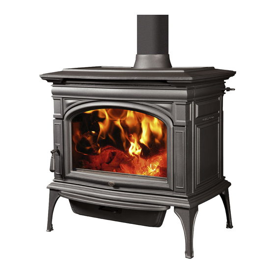
Cape Cod Wood Stove Owner's Manual • Freestanding Stove • Mobile-Home Approved • Alcove Approved • Hearth-Stove Approved Save these instructions for future reference SAFETY NOTICE: If this appliance is not properly installed, a house fire may result. For your safety, follow the installation directions. -
Page 2: Introduction
Introduction Introduction We welcome you as a new owner of a Lopi Cape Cod wood-burning stove. In purchasing a Cape Cod you have joined the growing ranks of concerned individuals whose selection of an energy system reflects both a concern for the environment and aesthetics. The Lopi Cape Cod is one of the finest appliances the world over. -
Page 3: Table Of Contents
Table of Contents Ash Pan Removal ..........23 Introduction ............2 Re-Loading the Stove ........24 Important Information ........2 Overnight Burn ..........24 Installation Options .......... 6 Normal Operating Sounds ......24 ... - Page 4 Safety Precautions The viewing door must be Gasoline or other flammable closed and latched during liquids must never be used to operation. start the fire or "Freshen Up" the fire. Do not store or use Smoke from this appliance may gasoline or other flammable active a smoke detector when liquids in the vicinity of this...
- Page 5 Safety Precautions When installed in a mobile home, this appliance must be Do not place clothing or other bolted to the floor, have outside flammable items on or near this air, and not be installed in the appliance. Mobile bedroom (per H.U.D. Home requirements).
-
Page 6: Installation Options
Features & Specifications Installation Options Features • Freestanding • EPA Phase II Approved • Freestanding in an Alcove • 3.0 Cubic Foot (0.278 M ) Firebox Volume • Freestanding in a Mobile Home • Single Operating Control • Optional GreenStart Igniter •... -
Page 7: Planning The Installation
Stove Installation (for qualified installers only) SAFETY NOTICE: Please read this entire manual before you install and use your new room heater. Failure to follow instructions may result in property damage, bodily injury, or even death. Contact local building or fire officials about restrictions and installation inspection requirements in your area. -
Page 8: Floor Protection Requirements
Stove Installation (for qualified installers only) Floor Protection Requirements • Floor protection must extend to the sides, rear, and front of the stove (see “Clearances” below for minimum floor protection). • Floor protection must be non-combustible and at least .018” (.45mm) thick (26 gauge). Stove Placement Requirements Clearances may be reduced by methods specified in NFPA 211, listed wall shields, pipe shields, or other means approved by local building or fire officials. -
Page 9: Top View - Straight Installation
Stove Installation (for qualified installers only) Typical Flue Center 29-1/2" 750mm Top View - Back Wall Clearance B Straight Installation Typical Flue Center Clearance E Singlewall 18" Reduced Clearance 15-1/2" Clearance G 2" 32-1/4" 821mm 51mm 3-1/4" Clearance D 83mm 19-3/4"... -
Page 10: Chimney Connector Requirements
Stove Installation (for qualified installers only) Chimney Connector Requirements • Chimney connector is required from the flue collar of the stove to the factory-built chimney or masonry chimney. • The chimney connector must be 6” (152mm) diameter and a minimum 24 gauge black steel, or one of the reduced-clearance connectors listed on page 8. -
Page 11: Chimney Requirements
Stove Installation (for qualified installers only) Chimney Requirements DO NOT CONNECT THIS UNIT TO A CHIMNEY FLUE SERVING ANOTHER APPLIANCE. • • DO NOT CONNECT TO OR USE IN CONJUNCTION WITH ANY AIR DISTRIBUTION DUCTWORK UNLESS SPECIFICALLY APPROVED FOR SUCH INSTALLATIONS •... -
Page 12: Chimney Termination Requirements
Stove Installation (for qualified installers only) Chimney Termination Requirements • Must have an approved cap (to prevent water from entering) • Must not be located where it will become plugged by snow or other material • Must terminate at least 3' (914mm) above the roof and at least 2' (610mm) above any portion of the roof within 10' (3.048M) (see Figure 5) Chimney must extend 2' Slanted Roofs... -
Page 13: Alcove Installation Requirements
Stove Installation (for qualified installers only) Alcove Installation Requirements Whenever the stove is placed in a location where the ceiling height is less than 7' (2.134M) tall, it is considered an alcove installation. Because of the reduced height, the special installation requirements listed below must be met. -
Page 14: Mobile Home Requirements
Stove Installation (for qualified installers only) Mobile Home Requirements • Outside air must be installed - see "Outside Air Requirements" on page 12 • Chimney connector and chimney must be one of the following types: AMERI-TEC model DCC with model HS chimney DURAVENT model DVL with DURATEC or DURA-PLUS chimney GSW Super Chimney Twenty-One connected directly to appliance I.C.C. -
Page 15: Standard Ceiling With A Factory-Built Chimney
Stove Installation (for qualified installers only) Chimney Cap Standard Ceiling (See the section "Chimney Termination Requirements" with a Factory- Follow the chimney for more details) manufacturer's instructions Built Chimney and clearances for roof penetrations. A storm collar and flashing are required (some require a radiation shield). -
Page 16: Exterior Factory-Built Chimney
Stove Installation (for qualified installers only) Exterior Factory-Built Chimney A vertical rise of 84” of chimney connector is required, measured from the floor, before entering a Class ‘A’ wall penetration. For those wishing to pass the chimney through the lower wall, a NFPA 211 wall pass-through may be used (if approved by local building codes). -
Page 17: Hearth Stove Installation
WARNING: We strongly recommend a full reline (positive Chimney connector sections connection) when venting through a masonry Make sure the chimney. The Cape Cod clean-out seals in See the section place. "Floor Protection is equipped with a Requirements" catalytic combustor and may draft poorly without a full reline. -
Page 18: Safety Notice
Operating Your Appliance Safety Notice If this appliance is not properly installed, a house fire may result. For your safety, follow the installation directions. Contact local building or fire officials about restrictions and installation inspection requirements in your area. Read and follow all of the warnings on pages 4 and 5 of this manual. Do not operate this stove with the ash pan open. -
Page 19: Opening The Door
Operating Your Appliance Opening the Door The door becomes hot during use. Use a glove to open the door if the handle is hot. Do not operate this stove with the door open. A fire hazard will result. To prevent smoke from entering the room, open the air control and bypass (see instructions below) before opening the door. -
Page 20: Catalytic Combustor - Use And Cleaning
Operating Your Appliance Catalytic Combustor – Use and Cleaning This heater uses a catalytic combustor to improve efficiency and reduce emissions. To work at its optimum, the combustor must be kept free of excessive ash. If the heater becomes sluggish when the bypass is closed, flyash may be building up on the combustor. -
Page 21: Starting A Fire
Operating Your Appliance Starting a Fire Use of the optional GreenStart igniter will greatly simplify this process. See page 38. Since the dawn of time man has debated the best way to start a fire. Some use the boy-scout "tee-pee"; some prefer the "tic-tac-toe"... -
Page 22: Adjusting The Burn Rate
Operating Your Appliance Adjusting the Burn Rate Use the air control slider to control the burn rate of the stove. See the illustration below for details. Use the air control to change the burn rate. Low Burn High Burn (air control closed) (air control open) Approximate Air Control Settings High Burn... -
Page 23: Ash Removal
Operating Your Appliance Ash Removal Ashes should be placed in a metal container with a tight fitting lid. The closed container of ashes should be placed on a noncombustible floor or on the ground, away from all combustible materials, ASHES pending final disposal. -
Page 24: Re-Loading The Stove
Operating Your Appliance Re-Loading the Stove Follow the directions below to minimize smoke spillage while re-loading the stove. Open the air control all the way (pull it out). Open the bypass. Open the door slightly. Let the airflow inside the firebox to stabilize before opening the doors fully. Load wood onto the fire. -
Page 25: Hints For Burning
Operating Your Appliance Hints for Burning • Get the appliance hot before adjusting to low burn • Use smaller pieces of wood during start-up and high burns to increase temperature • Use larger pieces of wood for overnight or sustained burns •... -
Page 26: Troubleshooting
Operating Your Appliance Troubleshooting Problem Possible Cause • Open the bypass and air control (pg. 22). Smoke Enters Room During • Cold Air Blockage - burn a piece of newspaper to Start-Up establish a draft. • If the flame is not getting enough air, a small crack in the door is all that is needed. -
Page 27: Daily Maintenance (While Stove Is In Use)
Maintaining Your Appliance Failure to properly maintain and inspect your appliance may reduce the performance and life of the appliance, void your warranty, and create a fire hazard. Use only specified components. Use of unauthorized components may result in property damage, injury, or even death. Establish a routine for the fuel, wood burner and firing technique. -
Page 28: Monthly Maintenance (While Appliance Is In Use)
Maintaining Your Appliance Monthly Maintenance (while appliance is in use) Make sure the appliance has fully cooled prior to conducting service. Door and Glass Inspection The door must form an air-tight seal to the firebox for the stove to work correctly. Inspect the door gasket to make sure it forms an air-tight seal to the firebox. -
Page 29: Creosote - Formation And Need For Removal
Maintaining Your Appliance Creosote - Formation and Need for Removal When wood is burned slowly, it produces tar and other organic vapors, which combine with expelled moisture to form creosote. The creosote vapors condense in the relatively cool chimney flue of a slow- burning fire. -
Page 30: Cleaning The Catalytic Combustor
Maintaining Your Appliance Cleaning the Catalytic Combustor Your combustor is available through an authorized Travis dealer. You can visually check the condition of your combustor by opening the door and looking above the baffle with a flashlight. If there is visible ash accumulation on the surface of your combustor it should be cleaned off with a soft bristled brush. -
Page 31: Door Parts
250-02832 Glass Gasket 250-02184 Screws (8) 8-32 x 1/2” Torx 225-20039 Cape Cod Door Handle Assy. 250-02074 Glass Clip w Gasket– 3 Hole 250-00174 Replacing the Glass The glass must not contact the door retainer or glass clips directly. The glass gasket and glass clip gaskets insulate the glass to prevent cracking. -
Page 32: Firebox Parts
Maintaining Your Appliance Firebox Parts ID # Description Qty. Part # ID # Description Qty. Part # Secondary Air Tubes Combustor Air Tube Pins Bypass Slider Baffle Bypass Yoke Assy. Baffle Insulation Combustor Gasket Baffle Removal & Replacement The baffle is held up by the 3 air tubes. Make sure to support the baffle while removing the air tubes. •... -
Page 33: Air Tube Removal & Replacement
Maintaining Your Appliance Air Tube Removal & Replacement VIEW FROM THE FRONT VIEW FROM THE REAR Air Tube Air Channel Air Tube Bolt Air Tube Pin Air Channel Air Tube Bolt AIR TUBE REMOVAL TUBE SIZING (all 3 tubes are identical) Front Tube = 24.2”... -
Page 34: Combustor Removal
Maintaining Your Appliance Combustor Removal To remove the combustor first remove the baffle (see page 32), open the bypass and reach through the bypass hole and push the combustor out from the rear. The combustor is housed in a stainless steel frame;... - Page 35 Limited 5 Year Warranty To register your TRAVIS INDUSTRIES, INC. 5 Year Warranty, complete the enclosed warranty card and mail it within ten (10) days of the appliance purchase date to: TRAVIS INDUSTRIES, INC., 12521 Harbour Reach Dr., Mukilteo, WA 98275. TRAVIS INDUSTRIES, INC.
- Page 36 Limited 5 Year Warranty CONDITIONS & EXCLUSIONS This new appliance must be installed by a qualified installer. It must be installed, operated, and maintained at all times in accordance with the instructions in the Owner’s Manual. Any alteration, willful abuse, accident, neglect, or misuse of the product shall nullify this warranty. 2.
-
Page 37: Listing Label
CONTACT LOCAL BUILDING OR FIRE OFFICIALS ABOUT INSTALLATION AND RESTRICTIONS IN YOUR AREA. SUITABLE FOR USE IN CONVENTIONAL RESIDENTIAL INSTALLATIONS, MANUFACTURED HOMES AND ALCOVES. SERIAL NO: MODEL: CAPE COD Report No. 100517863-001 Certified for USA and Canada Control No. 4000515 CONFORMS TO UL STD 1482;... -
Page 38: Rear Blower (Part # 99000139)
Optional Equipment Rear Blower (Part # 99000139) An optional rear blower is available for your stove. This accessory pushes heated air into the room. Contact your dealer for details. GreenStart™Woodstove Igniter (Part # 94400951) An optional GreenStart™ igniter is available for your stove. This accessory starts your fire with a simple push of the button. - Page 39 Optional Equipment © Travis Industries 100-01282_000 4111128...
- Page 40 Index Adjusting the Burn Rate ........22 Floor Protection Requirements ......8 Air Tube Removal & Replacement ....33 Heating Specifications ........6 Alcove Installation Requirements ..... 13 Hints for Burning ..........25 Ash Pan Removal ..........23 Installation Options ..........6 Ash Removal ............